US4424860A - Deflate-equalizing valve apparatus for inflatable packer formation tester - Google Patents
Deflate-equalizing valve apparatus for inflatable packer formation tester Download PDFInfo
- Publication number
- US4424860A US4424860A US06/266,899 US26689981A US4424860A US 4424860 A US4424860 A US 4424860A US 26689981 A US26689981 A US 26689981A US 4424860 A US4424860 A US 4424860A
- Authority
- US
- United States
- Prior art keywords
- passage
- inflation
- extended
- mandrel assembly
- housing
- Prior art date
- Legal status (The legal status is an assumption and is not a legal conclusion. Google has not performed a legal analysis and makes no representation as to the accuracy of the status listed.)
- Expired - Fee Related
Links
- 230000015572 biosynthetic process Effects 0.000 title description 8
- 238000012360 testing method Methods 0.000 claims abstract description 51
- 230000004044 response Effects 0.000 claims abstract description 4
- 239000012530 fluid Substances 0.000 claims description 23
- 230000000712 assembly Effects 0.000 claims description 13
- 238000000429 assembly Methods 0.000 claims description 13
- 238000004891 communication Methods 0.000 claims description 9
- 230000008878 coupling Effects 0.000 claims 1
- 238000010168 coupling process Methods 0.000 claims 1
- 238000005859 coupling reaction Methods 0.000 claims 1
- 230000000979 retarding effect Effects 0.000 claims 1
- 238000007789 sealing Methods 0.000 description 3
- 230000008901 benefit Effects 0.000 description 2
- 238000012986 modification Methods 0.000 description 2
- 230000004048 modification Effects 0.000 description 2
- 238000012856 packing Methods 0.000 description 2
- 125000006850 spacer group Chemical group 0.000 description 2
- 230000009471 action Effects 0.000 description 1
- 238000010276 construction Methods 0.000 description 1
- 238000013461 design Methods 0.000 description 1
- 206010016256 fatigue Diseases 0.000 description 1
- 238000007667 floating Methods 0.000 description 1
- 230000002706 hydrostatic effect Effects 0.000 description 1
- 230000007257 malfunction Effects 0.000 description 1
- 238000005086 pumping Methods 0.000 description 1
- 238000011084 recovery Methods 0.000 description 1
- XLYOFNOQVPJJNP-UHFFFAOYSA-N water Substances O XLYOFNOQVPJJNP-UHFFFAOYSA-N 0.000 description 1
Images

Classifications
-
- E—FIXED CONSTRUCTIONS
- E21—EARTH DRILLING; MINING
- E21B—EARTH DRILLING, e.g. DEEP DRILLING; OBTAINING OIL, GAS, WATER, SOLUBLE OR MELTABLE MATERIALS OR A SLURRY OF MINERALS FROM WELLS
- E21B49/00—Testing the nature of borehole walls; Formation testing; Methods or apparatus for obtaining samples of soil or well fluids, specially adapted to earth drilling or wells
- E21B49/08—Obtaining fluid samples or testing fluids, in boreholes or wells
- E21B49/087—Well testing, e.g. testing for reservoir productivity or formation parameters
-
- E—FIXED CONSTRUCTIONS
- E21—EARTH DRILLING; MINING
- E21B—EARTH DRILLING, e.g. DEEP DRILLING; OBTAINING OIL, GAS, WATER, SOLUBLE OR MELTABLE MATERIALS OR A SLURRY OF MINERALS FROM WELLS
- E21B33/00—Sealing or packing boreholes or wells
- E21B33/10—Sealing or packing boreholes or wells in the borehole
- E21B33/12—Packers; Plugs
- E21B33/124—Units with longitudinally-spaced plugs for isolating the intermediate space
- E21B33/1243—Units with longitudinally-spaced plugs for isolating the intermediate space with inflatable sleeves
- E21B33/1246—Units with longitudinally-spaced plugs for isolating the intermediate space with inflatable sleeves inflated by down-hole pumping means operated by a pipe string
-
- E—FIXED CONSTRUCTIONS
- E21—EARTH DRILLING; MINING
- E21B—EARTH DRILLING, e.g. DEEP DRILLING; OBTAINING OIL, GAS, WATER, SOLUBLE OR MELTABLE MATERIALS OR A SLURRY OF MINERALS FROM WELLS
- E21B34/00—Valve arrangements for boreholes or wells
- E21B34/06—Valve arrangements for boreholes or wells in wells
- E21B34/12—Valve arrangements for boreholes or wells in wells operated by movement of casings or tubings
- E21B34/125—Valve arrangements for boreholes or wells in wells operated by movement of casings or tubings with time delay systems, e.g. hydraulic impedance mechanisms
Definitions
- This invention relates generally to a drill stem testing system using inflatable packers, and particularly to a new and improved valve system for equalizing pressures across and enabling deflation of the packers during the course of a well testing operation.
- packer elements of the type that can be inflated by a downhole pump to isolate and seal off the well interval to be tested.
- pressure equalization must be stopped.
- the pressures must again be equalized and the packer elements deflated so that the string of tools can be removed from the well or moved to another test elevation therein.
- Another object of the present invention is to provide a new and improved valve system of the type described that is more compact and simple in construction and operation, and thus more reliable for use in well testing operations.
- valve apparatus comprising a housing having a mandrel assembly axially movable therein between extended and retracted positions.
- the housing and mandrel assembly define a test passage for conducting formation fluids from an isolated well interval, and an inflation passage that leads from a rotary operated pump to the interior of one or more inflatable packer elements.
- An equalizing port and a deflate port extend through the wall of the housing.
- the equalizating port is arranged to be placed in communication with the test passage in the extended position of the mandrel assembly to equalize pressures during initial packer inflation, and at the end of the test when the packer elements are to be deflated. In the contracted position of the mandrel assembly, communication between the equalizing port and the test passage is closed off.
- a passage between the housing and the mandrel assembly is arranged to communicate the deflate port with the inflation passage.
- This passage automatically is closed off by a shuttle valve when the inflation pump is started up to enable the packer elements to be inflated with the tool string in tension. Downward movement of the mandrel assembly with respect to the housing causes the passage to be closed off, and also forces the shuttle valve downward to a position where it closes the inflation passage.
- FIG. 1 is a schematic view of a string of drill stem testing tools, utilizing inflatable packers, suspended in a well bore;
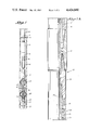
- FIGS. 2A-2C are cross-sectional views, with portions in side elevation, of a deflate-equalizing valve that is constructed in accordance with the present invention.
- FIG. 1 for a schematic illustration of the entire string of drill stem testing tools disposed in a well to be tested, the running-in string 10 of drill pipe or tubing is provided with a reverse circulating valve 11 of any typical design, for example, as shown in U.S. Pat. No. 2,863,511.
- a suitable length of pipe 12 is connected between the reversing valve 11 and a multi-flow evaluator or test valve assembly 13 that functions to alternately flow and shut-in the formation interval to be tested.
- a preferred form of test valve is shown in Nutter U.S. Pat. No. 3,308,887, assigned to the assignee of this invention.
- the lower end of the test valve 13 is connected to a recorder carrier 14 that houses a pressure recorder of the type shown in the assignee's U.S. Pat. No. 2,816,440, the recorder functioning to make a permanent record of fluid pressure versus elapsed time as the test proceeds.
- the recorder carrier 14 is connected to the upper end of a screen sub 15 through which well fluids are taken in during operation of a packer inflation pump assembly 16 connected to the lower end thereof.
- the pump assembly 16 is disclosed in Upchurch application Ser. No. 103,660, now U.S. Pat. No. 4,320,800, also assigned to the assignee of this invention. The disclosure of the said Upchurch application is incorporated herein by reference.
- Other rotary pumps such as the device shown in the above-mentioned Conover patent, or the Evans et al U.S. Pat. No. 3,926,254, could also be used.
- the lower end on the pump assembly 16 is connected to a pressure equalizing and packer deflating valve apparatus 17 that is constructed in accordance with the present invention.
- the valve 17 is coupled to the upper end of a straddle-type inflatable packer system that includes an upper packer element 18 and a lower packer element 18' that are connected together by an elongated spacer sub 19.
- the packer elements 18 and 18' each include an internally reinforced elastomeric sleeve that normally is retracted but which can be expanded outwardly by applied internal pressure into sealing contact with the surrounding well wall.
- the length of the spacer pipe 19 is selected such that during a test the upper packer 18 is above the upper end of the formation interval of interest, and the lower packer 18' is below the lower end of the interval.
- the lower end of the packer system is connected to the upper end of a deflate-drag spring tool 20 of the type disclosed in the aforementioned Upchurch application.
- the drag springs 21 associated with the tool 20 are bowed outwardly and frictionally engage the walls of the well bore to enable the relative rotation that is necessary to operate the pump assembly 16.
- Another recorder carrier 22 can be connected to the lower end of the drag spring tool 20 and houses pressure recorders that are arranged to measure directly the formation fluid pressure in the isolated interval. A comparison of the data recorded by this instrument with that recorded by the upper instrument 14 can indicate whether or not test passages and ports have been plugged or blocked by debris or the like during the test.
- FIGS. 2A-2C for an illustration of structural details of the delfate-equalizing valve 17, the lower end of the rotary pump housing 30 is connected by a collar 31 to the upper sub 32 of a mandrel assembly indicated generally at 33 that is telescopically disposed within a generally tubular housing 34.
- the mandrel assembly 33 includes a spline section 35 that has outwardly directed splines 36 which mesh with inwardly directed splines 37 on the upper end section 38 of the housing 34 to prevent relative rotation while enabling limited longitudinal relative movement.
- a hydraulic delay system includes a metering piston 40 that is movably mounted on a thickened portion 41 of an intermediate section 42 of the mandrel assembly, with the piston being sized to provide for a restricted leakage of hydraulic fluid contained in an annular chamber 43 from above the piston to below same during upward movement.
- the piston 40 can move away from an annular valve seat 44 during downward movement of the mandrel within the housing so that hydraulic fluid can pass freely through external grooves (not shown) in the mandrel section 41 behind the metering piston.
- the chamber 43 is closed at its upper end by a seal ring 45 and at its lower end by a floating balance piston 47 whose lower face is subjected to the pressure of fluids in the well annulus by one or more ports 48 extending through the wall of the cylinder section 50 of the housing 34.
- the balance piston 47 which carries inner and outer seal rings 51, 52, functions to transmit the pressure of well fluids to the hydraulic fluid below the piston 40 so that pressure in this region of the chamber is never less than the hydrostatic head pressure in the well bore outside the housing 34.
- An elongated flow tube 54 that is fixedly mounted within the mandrel assembly 33 has a central bore 55 that provides an upwardly extending passage for formation fluids that are recovered during the test.
- the outer periphery of the tube 54 is spaced inwardly of the inner wall surface of the mandrel assembly 33 to provide an inflation passage 56 that leads from the outlet ports 57 of the rotary pump 16 to the respective interiors of the packer assemblies 18 and 18'.
- the lower end portion of the flow tube 54 has one or more relief passage slots 58 that are disposed below the seals 60 of a sleeve 61 that is fixed within the housing 34 when the mandrel assembly 33 is telescoped downwardly to its lower position therein, and which are disposed above the seals 60 when the mandrel assembly is extended with respect to the housing.
- a valve section 62 of the housing 34 that is connected to the lower end of the cylinder section 50 has a seat sleeve 63 mounted therein.
- the sleeve 63 is sealed with respect to the mandrel section 42 and the section 50 by O-rings 64 and 65, and one or more inflation ports 66 extend laterally through the wall thereof intermediate its ends.
- the lower end portion 67 of the mandrel 42 constitutes a sleeve valve having circumferentially spaced, longitudinally extending flow grooves 68 located adjacent its lower end.
- a second valve sleeve 70 is mounted for independent vertical movement with respect to the seat sleeve 63 and mandrel portion 67, and has a reduced diameter upper section 80 that is sealed with respect to the portion 67 by an O-ring 81, and an enlarged diameter lower section 82 that is sealed with respect to the seat sleeve by O-ring 83.
- a small diameter port (not shown) can be provided near the lower end of the seat sleeve 63 for purposes to be described hereinafter.
- the annular region 85 outside the seat sleeve 63 is communicated with a lower continuation 86 of the packer inflation passage by several vertical ports 87 indicated in phantom lines in FIG. 2C.
- Radially offset from the ports 87 and formed in the same sub 88 is an equalizing port 89 that communicates with an interior space 90 within the housing.
- the string of testing tools is assembled end-to-end generally as shown in the drawings and run into the well bore.
- the drag springs 21 frictionally engage the walls of the bore hole to afford a degree of restraint to vertical as well as rotational movement.
- the pipe string 10 is either empty of fluids, or may contain a column of water to act as a cushion as will be apparent to those skilled in the art.
- the interior of the pipe string 10 provides a low pressure region which can be communicated with an isolated interval of the well to induce formation fluids to flow from the formation into the pipe string if they are capable of so doing.
- the interval is isolated by inflating the elements 18 and 18' into sealing contact with the well wall through operation of the pump assembly 16. This is accomplished by rotating the pipe string 10 to the right to cause the pump to intake well fluids from the annulus via the screen 15 and to exhaust same under pressure to the inflation passage 56.
- the mandrel assembly 33 will be in its extended position with respect to the housing 34 where the pressure relief slots 58 are located above the seals 60 so that the test passage 55 is in communication with the well annulus above the upper packer element via the space 90 and the lower port 89.
- Fluid pressure in the inflation passage 56 will act upwardly on the lower section 82 of the valve sleeve to shift it upwardly to a position where the seals 83 are above the port 66 to enable inflation fluids to pass downwardly through the annular region 85, the vertical ports 87 and the continuing passage 86 to the respective interiors of the packing elements 18 and 18' to cause them to inflate and thereby expand into sealing engagement with the surrounding well wall.
- the pump 16 automatically will cease pumping as described in the above-mentioned Upchurch patent application, whereupon rotation of the pipe string 10 is stopped.
- any well fluids that are displaced through enlargement of the packer elements can pass via the test ports 24, the test passage 19', 55, the slots 58 and the port 89 to the well annulus above the upper packer.
- the weight of the pipe string 10 is slacked off on the packers 18 and 18' to close the deflate-equalizing valve 17 and open the tester valve 13.
- the flow slots 58 are positioned below the seals 60 to close off annulus communication, and the valve head 82 is pushed down below the inflation ports 66 to close the inflation passage 56, 86.
- the outer surface of the mandrel section 67 above the flow slots 68 is engaged by the seals 64 to prevent communication between the inflation passage and the well annulus via the deflate ports 98.
- the pipe string 10 can be repeatedly lifted and lowered to open and close the tester valve 13 without opening the deflate-equalizing valve 17 because the hydraulic delay piston 40 retards upward movement.
- a strain is placed in the pipe string 10, and tension is maintained for a time sufficient to cause the delay piston 40 to reach the upper end of the chamber 43.
- the flow slots will span the seals 64 to communicate the inflation passage 85 with the well annulus via the deflate ports 98, and the equalizing slots 58 in the flow tube 54 are moved above the seals 60 to communicate the well interval being tested with the well annulus above the upper packer element 18 via the port 89.
- a new and improved apparatus has been provided for equalizing pressures and for enabling inflation and deflation of packer elements during the course of a drill stem test.
- a small port near the lower end of the seat sleeve 63 may be provided, and has the advantage of enabling the rotary pump assembly to be operated with pipe weight slacked-off on the tools.
- inflation fluid flow therethrough during initial operation of the pump with the mandrel assembly 33 extended provides a choking action and generation of a back pressure which will cause the valve head 82 to shift upward and close off communication between the inflation passage and the deflate ports 98, provided that the valve head was not already so positioned.
Abstract
Description
Claims (16)
Priority Applications (6)
| Application Number | Priority Date | Filing Date | Title |
|---|---|---|---|
| US06/266,899 US4424860A (en) | 1981-05-26 | 1981-05-26 | Deflate-equalizing valve apparatus for inflatable packer formation tester |
| EP82400923A EP0067096B1 (en) | 1981-05-26 | 1982-05-18 | Deflate-equalizing valve apparatus for inflatable packer formation tester |
| DE8282400923T DE3278978D1 (en) | 1981-05-26 | 1982-05-18 | Deflate-equalizing valve apparatus for inflatable packer formation tester |
| MX192822A MX157504A (en) | 1981-05-26 | 1982-05-24 | IMPROVED DEVICE FOR INFLATABLE SHUTTER TRAINING TESTER |
| ES512522A ES512522A0 (en) | 1981-05-26 | 1982-05-25 | "VALVE DEVICE ADAPTED TO BE USED IN CONJUNCTION WITH A PUMP, LOCATED WELL DOWN". |
| CA000403639A CA1184113A (en) | 1981-05-26 | 1982-05-25 | Deflate-equalizing valve apparatus for inflatable packer formation tester |
Applications Claiming Priority (1)
| Application Number | Priority Date | Filing Date | Title |
|---|---|---|---|
| US06/266,899 US4424860A (en) | 1981-05-26 | 1981-05-26 | Deflate-equalizing valve apparatus for inflatable packer formation tester |
Publications (1)
| Publication Number | Publication Date |
|---|---|
| US4424860A true US4424860A (en) | 1984-01-10 |
Family
ID=23016446
Family Applications (1)
| Application Number | Title | Priority Date | Filing Date |
|---|---|---|---|
| US06/266,899 Expired - Fee Related US4424860A (en) | 1981-05-26 | 1981-05-26 | Deflate-equalizing valve apparatus for inflatable packer formation tester |
Country Status (6)
| Country | Link |
|---|---|
| US (1) | US4424860A (en) |
| EP (1) | EP0067096B1 (en) |
| CA (1) | CA1184113A (en) |
| DE (1) | DE3278978D1 (en) |
| ES (1) | ES512522A0 (en) |
| MX (1) | MX157504A (en) |
Cited By (27)
| Publication number | Priority date | Publication date | Assignee | Title |
|---|---|---|---|---|
| US4569396A (en) * | 1984-10-12 | 1986-02-11 | Halliburton Company | Selective injection packer |
| US4660426A (en) * | 1985-05-20 | 1987-04-28 | Infinity Pumping Systems | Pumping unit for actuating a down hole pump with static and dynamic counterweights |
| EP0265054A2 (en) * | 1986-10-22 | 1988-04-27 | Halliburton Company | Downhole string bypass apparatus |
| EP0271297A2 (en) * | 1986-12-10 | 1988-06-15 | Halliburton Company | Packer bypass |
| US4776396A (en) * | 1986-03-07 | 1988-10-11 | Mandarin Oilfield Services Ltd. | Apparatus for controlling inflation fluid to and from inflatable packer elements |
| US4800752A (en) * | 1987-07-01 | 1989-01-31 | Schlumberger Technology Corporation | Flow restricting logging tool and method |
| US5271461A (en) * | 1992-05-13 | 1993-12-21 | Halliburton Company | Coiled tubing deployed inflatable stimulation tool |
| US5375662A (en) * | 1991-08-12 | 1994-12-27 | Halliburton Company | Hydraulic setting sleeve |
| US5383520A (en) * | 1992-09-22 | 1995-01-24 | Halliburton Company | Coiled tubing inflatable packer with circulating port |
| US5392657A (en) * | 1991-02-13 | 1995-02-28 | Onicon Incorporated | Flow sensor having high impedance circuit with capacitive sensing electrode |
| US5832998A (en) * | 1995-05-03 | 1998-11-10 | Halliburton Company | Coiled tubing deployed inflatable stimulation tool |
| WO1999022114A1 (en) * | 1997-10-24 | 1999-05-06 | Baird Jeffrey D | Method and apparatus for shutting in a well while leaving drill stem in the borehole |
| WO2002035054A1 (en) * | 2000-10-26 | 2002-05-02 | Halliburton Energy Services, Inc | Method and apparatus for in-situ production well testing |
| US6431273B1 (en) * | 1998-01-20 | 2002-08-13 | Smith International Inc. | Inflatable packer |
| US6530428B1 (en) | 2000-10-26 | 2003-03-11 | Halliburton Energy Services, Inc. | Method and apparatus for in-situ production well testing |
| US6547011B2 (en) * | 1998-11-02 | 2003-04-15 | Halliburton Energy Services, Inc. | Method and apparatus for controlling fluid flow within wellbore with selectively set and unset packer assembly |
| US20060169466A1 (en) * | 2005-02-02 | 2006-08-03 | Stokley Charles O | Packer with positionable collar |
| US20070056749A1 (en) * | 2005-09-14 | 2007-03-15 | Schlumberger Technology Corporation | Dynamic Inflatable Sealing Device |
| US20080190605A1 (en) * | 2007-02-12 | 2008-08-14 | Timothy Dale Clapp | Apparatus and methods of flow testing formation zones |
| US20100252252A1 (en) * | 2009-04-02 | 2010-10-07 | Enhanced Oilfield Technologies, Llc | Hydraulic setting assembly |
| US20110162835A1 (en) * | 2008-06-04 | 2011-07-07 | Gray Kevin L | Interface for deploying wireline tools with non-electric string |
| US20110168389A1 (en) * | 2010-01-08 | 2011-07-14 | Meijs Raymund J | Surface Controlled Downhole Shut-In Valve |
| WO2012155197A1 (en) * | 2011-05-13 | 2012-11-22 | Inflatable Packers International Pty Ltd | Balanced piston setting tool |
| US8684096B2 (en) | 2009-04-02 | 2014-04-01 | Key Energy Services, Llc | Anchor assembly and method of installing anchors |
| US9303477B2 (en) | 2009-04-02 | 2016-04-05 | Michael J. Harris | Methods and apparatus for cementing wells |
| US9500057B2 (en) | 2014-07-09 | 2016-11-22 | Saudi Arabia Oil Company | Apparatus and method for preventing tubing casing annulus pressure communication |
| CN112878951A (en) * | 2021-01-18 | 2021-06-01 | 大庆油田有限责任公司 | Time-delay setting shear pin packer |
Families Citing this family (3)
| Publication number | Priority date | Publication date | Assignee | Title |
|---|---|---|---|---|
| US4913231A (en) * | 1988-12-09 | 1990-04-03 | Dowell Schlumberger | Tool for treating subterranean wells |
| US4962815A (en) * | 1989-07-17 | 1990-10-16 | Halliburton Company | Inflatable straddle packer |
| FR2687725B1 (en) * | 1992-02-25 | 1994-05-27 | Services Projets | TEST TOOL FOR WELL OPERATION. |
Family Cites Families (3)
| Publication number | Priority date | Publication date | Assignee | Title |
|---|---|---|---|---|
| US3439740A (en) * | 1966-07-26 | 1969-04-22 | George E Conover | Inflatable testing and treating tool and method of using |
| US3876003A (en) * | 1973-10-29 | 1975-04-08 | Schlumberger Technology Corp | Drill stem testing methods and apparatus utilizing inflatable packer elements |
| US3926254A (en) * | 1974-12-20 | 1975-12-16 | Halliburton Co | Down-hole pump and inflatable packer apparatus |
-
1981
- 1981-05-26 US US06/266,899 patent/US4424860A/en not_active Expired - Fee Related
-
1982
- 1982-05-18 DE DE8282400923T patent/DE3278978D1/en not_active Expired
- 1982-05-18 EP EP82400923A patent/EP0067096B1/en not_active Expired
- 1982-05-24 MX MX192822A patent/MX157504A/en unknown
- 1982-05-25 ES ES512522A patent/ES512522A0/en active Granted
- 1982-05-25 CA CA000403639A patent/CA1184113A/en not_active Expired
Cited By (40)
| Publication number | Priority date | Publication date | Assignee | Title |
|---|---|---|---|---|
| US4569396A (en) * | 1984-10-12 | 1986-02-11 | Halliburton Company | Selective injection packer |
| US4660426A (en) * | 1985-05-20 | 1987-04-28 | Infinity Pumping Systems | Pumping unit for actuating a down hole pump with static and dynamic counterweights |
| US4776396A (en) * | 1986-03-07 | 1988-10-11 | Mandarin Oilfield Services Ltd. | Apparatus for controlling inflation fluid to and from inflatable packer elements |
| EP0265054A2 (en) * | 1986-10-22 | 1988-04-27 | Halliburton Company | Downhole string bypass apparatus |
| EP0265054A3 (en) * | 1986-10-22 | 1989-11-08 | Halliburton Company | Downhole string bypass apparatus |
| EP0271297A2 (en) * | 1986-12-10 | 1988-06-15 | Halliburton Company | Packer bypass |
| EP0271297A3 (en) * | 1986-12-10 | 1989-07-12 | Halliburton Company | Packer bypass |
| US4800752A (en) * | 1987-07-01 | 1989-01-31 | Schlumberger Technology Corporation | Flow restricting logging tool and method |
| US5392657A (en) * | 1991-02-13 | 1995-02-28 | Onicon Incorporated | Flow sensor having high impedance circuit with capacitive sensing electrode |
| US5375662A (en) * | 1991-08-12 | 1994-12-27 | Halliburton Company | Hydraulic setting sleeve |
| US5271461A (en) * | 1992-05-13 | 1993-12-21 | Halliburton Company | Coiled tubing deployed inflatable stimulation tool |
| US5383520A (en) * | 1992-09-22 | 1995-01-24 | Halliburton Company | Coiled tubing inflatable packer with circulating port |
| US5456322A (en) * | 1992-09-22 | 1995-10-10 | Halliburton Company | Coiled tubing inflatable packer with circulating port |
| US5832998A (en) * | 1995-05-03 | 1998-11-10 | Halliburton Company | Coiled tubing deployed inflatable stimulation tool |
| WO1999022114A1 (en) * | 1997-10-24 | 1999-05-06 | Baird Jeffrey D | Method and apparatus for shutting in a well while leaving drill stem in the borehole |
| US6431273B1 (en) * | 1998-01-20 | 2002-08-13 | Smith International Inc. | Inflatable packer |
| US6547011B2 (en) * | 1998-11-02 | 2003-04-15 | Halliburton Energy Services, Inc. | Method and apparatus for controlling fluid flow within wellbore with selectively set and unset packer assembly |
| GB2387404B (en) * | 2000-10-26 | 2004-06-09 | Halliburton Energy Serv Inc | Method and apparatus for in-situ production well testing |
| GB2387404A (en) * | 2000-10-26 | 2003-10-15 | Halliburton Energy Serv Inc | Method and apparatus for in-situ production well testing |
| WO2002035054A1 (en) * | 2000-10-26 | 2002-05-02 | Halliburton Energy Services, Inc | Method and apparatus for in-situ production well testing |
| US6530428B1 (en) | 2000-10-26 | 2003-03-11 | Halliburton Energy Services, Inc. | Method and apparatus for in-situ production well testing |
| US20060169466A1 (en) * | 2005-02-02 | 2006-08-03 | Stokley Charles O | Packer with positionable collar |
| US7284619B2 (en) | 2005-02-02 | 2007-10-23 | Tam International, Inc. | Packer with positionable collar |
| US20070056749A1 (en) * | 2005-09-14 | 2007-03-15 | Schlumberger Technology Corporation | Dynamic Inflatable Sealing Device |
| US7387157B2 (en) | 2005-09-14 | 2008-06-17 | Schlumberger Technology Corporation | Dynamic inflatable sealing device |
| US8286703B2 (en) | 2007-02-12 | 2012-10-16 | Weatherford/Lamb, Inc. | Apparatus and methods of flow testing formation zones |
| US20080190605A1 (en) * | 2007-02-12 | 2008-08-14 | Timothy Dale Clapp | Apparatus and methods of flow testing formation zones |
| WO2008100964A1 (en) * | 2007-02-12 | 2008-08-21 | Weatherford/Lamb, Inc. | Apparatus and methods of flow testing formation zones |
| US8720554B2 (en) | 2007-02-12 | 2014-05-13 | Weatherford/Lamb, Inc. | Apparatus and methods of flow testing formation zones |
| US20110162835A1 (en) * | 2008-06-04 | 2011-07-07 | Gray Kevin L | Interface for deploying wireline tools with non-electric string |
| US8469087B2 (en) | 2008-06-04 | 2013-06-25 | Weatherford/Lamb, Inc. | Interface for deploying wireline tools with non-electric string |
| US8453729B2 (en) | 2009-04-02 | 2013-06-04 | Key Energy Services, Llc | Hydraulic setting assembly |
| US8684096B2 (en) | 2009-04-02 | 2014-04-01 | Key Energy Services, Llc | Anchor assembly and method of installing anchors |
| US20100252252A1 (en) * | 2009-04-02 | 2010-10-07 | Enhanced Oilfield Technologies, Llc | Hydraulic setting assembly |
| US9303477B2 (en) | 2009-04-02 | 2016-04-05 | Michael J. Harris | Methods and apparatus for cementing wells |
| US20110168389A1 (en) * | 2010-01-08 | 2011-07-14 | Meijs Raymund J | Surface Controlled Downhole Shut-In Valve |
| WO2012155197A1 (en) * | 2011-05-13 | 2012-11-22 | Inflatable Packers International Pty Ltd | Balanced piston setting tool |
| US9500057B2 (en) | 2014-07-09 | 2016-11-22 | Saudi Arabia Oil Company | Apparatus and method for preventing tubing casing annulus pressure communication |
| CN112878951A (en) * | 2021-01-18 | 2021-06-01 | 大庆油田有限责任公司 | Time-delay setting shear pin packer |
| CN112878951B (en) * | 2021-01-18 | 2022-12-30 | 大庆油田有限责任公司 | Time-delay setting shear pin packer |
Also Published As
| Publication number | Publication date |
|---|---|
| EP0067096A3 (en) | 1985-07-17 |
| EP0067096A2 (en) | 1982-12-15 |
| ES8305876A1 (en) | 1983-04-16 |
| DE3278978D1 (en) | 1988-10-06 |
| EP0067096B1 (en) | 1988-08-31 |
| MX157504A (en) | 1988-11-28 |
| ES512522A0 (en) | 1983-04-16 |
| CA1184113A (en) | 1985-03-19 |
Similar Documents
| Publication | Publication Date | Title |
|---|---|---|
| US4424860A (en) | Deflate-equalizing valve apparatus for inflatable packer formation tester | |
| US3876000A (en) | Inflatable packer drill stem testing apparatus | |
| US4320800A (en) | Inflatable packer drill stem testing system | |
| US3876003A (en) | Drill stem testing methods and apparatus utilizing inflatable packer elements | |
| US4569396A (en) | Selective injection packer | |
| US6006834A (en) | Formation evaluation testing apparatus and associated methods | |
| US3969937A (en) | Method and apparatus for testing wells | |
| US4429748A (en) | Low pressure responsive APR tester valve | |
| US4345648A (en) | Inflatable packer system | |
| US6148664A (en) | Method and apparatus for shutting in a well while leaving drill stem in the borehole | |
| US5791414A (en) | Early evaluation formation testing system | |
| US3796261A (en) | Releasable connection for pressure controlled test valve system | |
| CA2168053C (en) | Packer inflation system | |
| GB1598863A (en) | Well tubing tester valve apparatus | |
| US3853177A (en) | Automatic subsurface blowout prevention | |
| US3824850A (en) | Pressure controlled test valve system for offshore wells | |
| USRE32345E (en) | Packer valve arrangement | |
| US3889750A (en) | Setting and releasing apparatus for sidewall anchor | |
| US3085628A (en) | Inflatable well tool | |
| US3662826A (en) | Offshore drill stem testing | |
| EP0055960B1 (en) | Full-bore well tester with hydrostatic bias | |
| US4577696A (en) | Sequential inflatable packer | |
| US3500911A (en) | Multiple packer distribution valve and method | |
| US3901314A (en) | Pressure controlled tester valve | |
| AU2004201438B2 (en) | Testing drill packer |
Legal Events
| Date | Code | Title | Description |
|---|---|---|---|
| AS | Assignment |
Owner name: SCHLUMBERGER TECHNOLOGY CORPORATION, 277 PARK AVE. Free format text: ASSIGNMENT OF ASSIGNORS INTEREST.;ASSIGNOR:MC GILL, HOWARD L.;REEL/FRAME:003891/0149 Effective date: 19810515 |
|
| FEPP | Fee payment procedure |
Free format text: MAINTENANCE FEE REMINDER MAILED (ORIGINAL EVENT CODE: REM.); ENTITY STATUS OF PATENT OWNER: LARGE ENTITY |
|
| FEPP | Fee payment procedure |
Free format text: SURCHARGE FOR LATE PAYMENT, PL 96-517 (ORIGINAL EVENT CODE: M176); ENTITY STATUS OF PATENT OWNER: LARGE ENTITY |
|
| MAFP | Maintenance fee payment |
Free format text: PAYMENT OF MAINTENANCE FEE, 4TH YEAR, PL 96-517 (ORIGINAL EVENT CODE: M170); ENTITY STATUS OF PATENT OWNER: LARGE ENTITY Year of fee payment: 4 |
|
| FEPP | Fee payment procedure |
Free format text: PAYOR NUMBER ASSIGNED (ORIGINAL EVENT CODE: ASPN); ENTITY STATUS OF PATENT OWNER: LARGE ENTITY |
|
| MAFP | Maintenance fee payment |
Free format text: PAYMENT OF MAINTENANCE FEE, 8TH YEAR, PL 96-517 (ORIGINAL EVENT CODE: M171); ENTITY STATUS OF PATENT OWNER: LARGE ENTITY Year of fee payment: 8 |
|
| FEPP | Fee payment procedure |
Free format text: MAINTENANCE FEE REMINDER MAILED (ORIGINAL EVENT CODE: REM.); ENTITY STATUS OF PATENT OWNER: LARGE ENTITY |
|
| LAPS | Lapse for failure to pay maintenance fees | ||
| FP | Lapsed due to failure to pay maintenance fee |
Effective date: 19960110 |
|
| STCH | Information on status: patent discontinuation |
Free format text: PATENT EXPIRED DUE TO NONPAYMENT OF MAINTENANCE FEES UNDER 37 CFR 1.362 |