US4446830A - Method of operating an engine with a high heat of vaporization fuel - Google Patents
Method of operating an engine with a high heat of vaporization fuel Download PDFInfo
- Publication number
- US4446830A US4446830A US06/465,858 US46585883A US4446830A US 4446830 A US4446830 A US 4446830A US 46585883 A US46585883 A US 46585883A US 4446830 A US4446830 A US 4446830A
- Authority
- US
- United States
- Prior art keywords
- fuel
- piston
- injected
- chamber
- cavity
- Prior art date
- Legal status (The legal status is an assumption and is not a legal conclusion. Google has not performed a legal analysis and makes no representation as to the accuracy of the status listed.)
- Expired - Fee Related
Links
Images
Classifications
-
- F—MECHANICAL ENGINEERING; LIGHTING; HEATING; WEAPONS; BLASTING
- F02—COMBUSTION ENGINES; HOT-GAS OR COMBUSTION-PRODUCT ENGINE PLANTS
- F02F—CYLINDERS, PISTONS OR CASINGS, FOR COMBUSTION ENGINES; ARRANGEMENTS OF SEALINGS IN COMBUSTION ENGINES
- F02F1/00—Cylinders; Cylinder heads
- F02F1/24—Cylinder heads
- F02F1/242—Arrangement of spark plugs or injectors
-
- F—MECHANICAL ENGINEERING; LIGHTING; HEATING; WEAPONS; BLASTING
- F02—COMBUSTION ENGINES; HOT-GAS OR COMBUSTION-PRODUCT ENGINE PLANTS
- F02B—INTERNAL-COMBUSTION PISTON ENGINES; COMBUSTION ENGINES IN GENERAL
- F02B17/00—Engines characterised by means for effecting stratification of charge in cylinders
- F02B17/005—Engines characterised by means for effecting stratification of charge in cylinders having direct injection in the combustion chamber
-
- F—MECHANICAL ENGINEERING; LIGHTING; HEATING; WEAPONS; BLASTING
- F02—COMBUSTION ENGINES; HOT-GAS OR COMBUSTION-PRODUCT ENGINE PLANTS
- F02B—INTERNAL-COMBUSTION PISTON ENGINES; COMBUSTION ENGINES IN GENERAL
- F02B23/00—Other engines characterised by special shape or construction of combustion chambers to improve operation
- F02B23/08—Other engines characterised by special shape or construction of combustion chambers to improve operation with positive ignition
- F02B23/10—Other engines characterised by special shape or construction of combustion chambers to improve operation with positive ignition with separate admission of air and fuel into cylinder
- F02B23/101—Other engines characterised by special shape or construction of combustion chambers to improve operation with positive ignition with separate admission of air and fuel into cylinder the injector being placed on or close to the cylinder centre axis, e.g. with mixture formation using spray guided concepts
-
- F—MECHANICAL ENGINEERING; LIGHTING; HEATING; WEAPONS; BLASTING
- F02—COMBUSTION ENGINES; HOT-GAS OR COMBUSTION-PRODUCT ENGINE PLANTS
- F02F—CYLINDERS, PISTONS OR CASINGS, FOR COMBUSTION ENGINES; ARRANGEMENTS OF SEALINGS IN COMBUSTION ENGINES
- F02F3/00—Pistons
- F02F3/26—Pistons having combustion chamber in piston head
-
- F—MECHANICAL ENGINEERING; LIGHTING; HEATING; WEAPONS; BLASTING
- F02—COMBUSTION ENGINES; HOT-GAS OR COMBUSTION-PRODUCT ENGINE PLANTS
- F02B—INTERNAL-COMBUSTION PISTON ENGINES; COMBUSTION ENGINES IN GENERAL
- F02B1/00—Engines characterised by fuel-air mixture compression
- F02B1/02—Engines characterised by fuel-air mixture compression with positive ignition
-
- F—MECHANICAL ENGINEERING; LIGHTING; HEATING; WEAPONS; BLASTING
- F02—COMBUSTION ENGINES; HOT-GAS OR COMBUSTION-PRODUCT ENGINE PLANTS
- F02B—INTERNAL-COMBUSTION PISTON ENGINES; COMBUSTION ENGINES IN GENERAL
- F02B23/00—Other engines characterised by special shape or construction of combustion chambers to improve operation
- F02B23/08—Other engines characterised by special shape or construction of combustion chambers to improve operation with positive ignition
- F02B23/10—Other engines characterised by special shape or construction of combustion chambers to improve operation with positive ignition with separate admission of air and fuel into cylinder
- F02B2023/108—Swirl flow, i.e. the axis of rotation of the main charge flow motion is vertical
-
- F—MECHANICAL ENGINEERING; LIGHTING; HEATING; WEAPONS; BLASTING
- F02—COMBUSTION ENGINES; HOT-GAS OR COMBUSTION-PRODUCT ENGINE PLANTS
- F02B—INTERNAL-COMBUSTION PISTON ENGINES; COMBUSTION ENGINES IN GENERAL
- F02B75/00—Other engines
- F02B75/12—Other methods of operation
- F02B2075/125—Direct injection in the combustion chamber for spark ignition engines, i.e. not in pre-combustion chamber
-
- F—MECHANICAL ENGINEERING; LIGHTING; HEATING; WEAPONS; BLASTING
- F02—COMBUSTION ENGINES; HOT-GAS OR COMBUSTION-PRODUCT ENGINE PLANTS
- F02B—INTERNAL-COMBUSTION PISTON ENGINES; COMBUSTION ENGINES IN GENERAL
- F02B2275/00—Other engines, components or details, not provided for in other groups of this subclass
- F02B2275/40—Squish effect
-
- Y—GENERAL TAGGING OF NEW TECHNOLOGICAL DEVELOPMENTS; GENERAL TAGGING OF CROSS-SECTIONAL TECHNOLOGIES SPANNING OVER SEVERAL SECTIONS OF THE IPC; TECHNICAL SUBJECTS COVERED BY FORMER USPC CROSS-REFERENCE ART COLLECTIONS [XRACs] AND DIGESTS
- Y02—TECHNOLOGIES OR APPLICATIONS FOR MITIGATION OR ADAPTATION AGAINST CLIMATE CHANGE
- Y02T—CLIMATE CHANGE MITIGATION TECHNOLOGIES RELATED TO TRANSPORTATION
- Y02T10/00—Road transport of goods or passengers
- Y02T10/10—Internal combustion engine [ICE] based vehicles
- Y02T10/12—Improving ICE efficiencies
Definitions
- This invention relates to a method of operating a spark ignition type internal combustion engine with a fuel having a high latent heat of vaporization such as methanol and the like. More particularly, it relates to a method of operating an engine in which the fuel is introduced in a first stage to evaporate and atomize the major portion of the fuel and subsequently in a second stage to provide a rich air/fuel mixture in the vicinity of the spark plug for rapid ignition.
- Methanol is a prime candidate for alternate piston engine fuel because it has a high octane rating and is readily producible from coal.
- the drawbacks associated with methanol are its high latent heat of evaporation, its low heat energy heat content, and its tendency to dilute the lubricating oil and thereby cause increased piston ring and cylinder bore wear.
- Methanol can be introduced into the engine in a variety of ways.
- carbureted methanol introduction the high latent heat of vaporization causes difficulties in getting the fuel evenly distributed in the intake air as it flows through the intake system to the cylinders.
- the usual remedy for this is to apply a large amount of heating to the intake system to assist evaporation.
- liquid methanol droplets still enter the cylinder where they can precipitate on the cylinder walls resulting in the dilution of the lubricating oil, which leads to accelerated cylinder wall and piston ring wear.
- Injection of the methanol in the intake manifold with multi-point injections is another possibility for fuel introduction.
- This method eliminates the cylinder-to-cylinder fuel distribution problem, but it does not eliminate the probability of oil dilution on the cylinder wall. In fact, it may increase the oil dilution problem relative to a carbureted methanol introduction because of the reduced time available for evaporation and because no exhaust heat is transferred to the methanol.
- This invention relates to a method of operating an engine that overcomes the above shortcomings by providing a two-stage introduction of methanol to the engine combustion chamber.
- a part of the combustion chamber in this case includes a central cavity in the face of the piston within which the major portion of the fuel is sprayed to be contained for evaporation and atomization to thereby minimize cylinder wall wetting.
- John, U.S. Pat. No. 4,117,810 describes a device for mixing both gasoline and methanol for use in an engine, and no description is given of the combustion chamber or the method of operating the engine in a manner to avoid the problems described above.
- Eckert et al U.S. Pat. No. 4,022,165, describes a fuel injection system in which two separate fuel quantities are injected into the engine with a time lag between. Two separate fuel injection nozzles are used for injecting first a large quantity of fuel and subsequently a smaller quantity into the same cylinder during one engine working cycle. The large quantity of fuel is injected in a straight jet deep into the cylinder while the smaller quantity is introduced in the vicinity of the spark plug.
- no description of the combustion chamber operation is given nor any method disclosed as to the timing and motion of the air/fuel charge to avoid wall wetting and oil dilution.
- Araya et al U.S. Pat. No. 3,722,490, also discloses a two-stage fuel injection system with, however, the injection occuring first at a point near the end of the intake or expansion stroke and, secondly, at a point at the beginning of the compression stroke. This is unlike our method and would be unsatisfactory for overcoming the shortcomings mentioned above.
- Fricker et al U.S. Pat. No. 3,641,986, shows only a bowl-in-piston type combustion chamber with tangential entry portions.
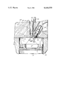
- the sole FIGURE shows a cross section of a spark ignition internal combustion engine.
- FIG. 1 shows a portion 10 of a spark ignition type internal combustion engine. It includes the usual cylinder block 12 within which is slidably mounted a piston 14 for cooperation with the face 16 of a cylinder head 18 to define a combustion chamber 20 between the two.
- piston 14 has a central cavity 22 defining a bowl-in-piston type construction.
- the cavity 22 would be designed to provide approximately 40-75% of the squish area, and the engine per se would operate at about a 13:1 compression ratio to make the best use of the methanol fuel.
- the cylinder head 18 contains the usual intake and exhaust valves 24, 26.
- Valve 24 is supplied with air through an inlet passage 28 that would be designed for a moderate rate of swirl.
- the exhaust gases exit through an outlet passage 30 that could be lined with ceramic or sheet metal for better heat conservation purposes.
- the fuel injector is centrally located in cylinder head 18 to project its nozzle 34 essentially into the center of combustion chamber 20 over cavity 22.
- the injector would be of a known type, and its details of construction and operation, therefore, are not given. Suffice it to say that in this case the pump system supplying the nozzle 34 would operate at a moderate pressure level (260 psi opening pressure for the injector), and the nozzle per se would be designed to provide a conical fuel spray with reasonably good atomization and relatively low penetration characteristics, for a purpose to be described.
- a spark plug 36 is located as close to the center of the combustion chamber as possible to project its electrodes adjacent the tip of the fuel injection nozzle 34, as indicated.
- the piston 14 is illustrated in a position after the engine has rotated through a crank angle of approximately 65° after top dead center position. Also illustrated is a conical spray angle of approximately 80° for the fuel from injection nozzle 34, as indicated by the dot/dash lines. If fuel is injected when piston 14 is near the top dead center position, it will be clear that substantially all of the fuel injected will pass directly into cavity 22 and not wet the cylinder walls. If only a small amount of fuel is injected, it will be contained near the tip of nozzle 34 and adjacent the spark plug electrodes to provide a rich air/fuel mixture in this area for ignition.
- a key feature of the invention is the unique timing of the fuel injection to provide initially a large charge of fuel sufficiently prior to ignition so it can be evaporated and atomized, and a secondary charge at a time and location to provide a dependable ignition of the air/fuel charge.
- the engine operates with a combustion method as follows.
- the opening of intake valve 24 will provide an induction of air or gas into the combustion chamber 20 with a moderate swirling motion.
- piston 14 begins its downward descent from its top dead center position, a first large (approximately 75-90% of the total) charge of fuel will be injected from nozzle 34 into combustion chamber 20.
- this total charge of fuel will be directed into the cavity 22 in piston 14.
- the incoming swirling air will pass into cavity 22 to evaporate and finely atomize the fuel.
- the fuel will be injected at a fast rate for a short duration to be completed approximately by the time piston 14 reaches the position indicated in the FIGURE.
- injection of the first portion of fuel is terminated between about 50°-60° after top dead center position at the start of the intake stroke.
- the evaporated as well as finely atomized fuel mist will disperse from cavity 22 outwardly to the rest of the cylinder space 20.
- This arrangement makes it unlikely for large fuel droplets to contact the cylinder walls because they would be centrifuged out to the chamber wall inside the combustion cavity 22 where they will absorb heat from the chamber wall as they evaporate.
- the evaporation of airborne fuel during this intake stroke also cools the intake charge and thus improves the volumetric efficiency of the engine.
- the cooler intake temperature also results in overall lower cycle temperatures that improve the thermal efficiency and reduce the oxides of nitrogen (NOx) that would be formed during the combustion.
- NOx oxides of nitrogen
- This invention eliminates the above problems by a two-stage fuel injection into a bowl-in-piston type combustion chamber that atomizes and evaporates the fuel in a manner providing good volumetric efficiency.
- the heat necessary for evaporation is taken from the surrounding cylinder wall and piston surfaces, which cools the same; also from the incoming charge of air or gas, which again improves the volumetric and thermal efficiencies.
- the invention provides a method of operating an automotive type internal combustion engine with a fuel having a high latent heat of vaporization so that the fuel does not wet the cylinder surfaces, and the heat required for evaporation is taken from the inducted air and the piston surfaces. Cooling of the inducted air improves the volumetric and thermal efficiencies and reduces NOx formation. Cooling of the piston improves its durability and facilitates supercharging of an engine without having to resort to excessive and costly piston cooling measures. Furthermore, good mechanical atomization of the fuel directly in the cylinder as provided by this invention eliminates the need to apply intake heat, yet it assures good fuel distribution.
- the direct fuel injection of the major portion of the fuel with the specified timing method described minimizes the probability of methanol diluting the oil film on the cylinder wall. Also, the second stage injection of a smaller quantity of fuel just prior to ignition facilitates operation of the engine with a lean mixture and a high EGR rate without endangering ignitability.
Abstract
Description
Claims (7)
Priority Applications (3)
| Application Number | Priority Date | Filing Date | Title |
|---|---|---|---|
| US06/465,858 US4446830A (en) | 1983-01-10 | 1983-01-10 | Method of operating an engine with a high heat of vaporization fuel |
| DE3400306A DE3400306C1 (en) | 1983-01-10 | 1984-01-05 | Method for operating an externally ignited internal combustion engine of motor vehicles |
| GB08400489A GB2133468B (en) | 1983-01-10 | 1984-01-10 | Method of direct injection of high heat of vaporisation fuel, e.g. methanol |
Applications Claiming Priority (1)
| Application Number | Priority Date | Filing Date | Title |
|---|---|---|---|
| US06/465,858 US4446830A (en) | 1983-01-10 | 1983-01-10 | Method of operating an engine with a high heat of vaporization fuel |
Publications (1)
| Publication Number | Publication Date |
|---|---|
| US4446830A true US4446830A (en) | 1984-05-08 |
Family
ID=23849462
Family Applications (1)
| Application Number | Title | Priority Date | Filing Date |
|---|---|---|---|
| US06/465,858 Expired - Fee Related US4446830A (en) | 1983-01-10 | 1983-01-10 | Method of operating an engine with a high heat of vaporization fuel |
Country Status (3)
| Country | Link |
|---|---|
| US (1) | US4446830A (en) |
| DE (1) | DE3400306C1 (en) |
| GB (1) | GB2133468B (en) |
Cited By (40)
| Publication number | Priority date | Publication date | Assignee | Title |
|---|---|---|---|---|
| FR2605057A1 (en) * | 1986-10-14 | 1988-04-15 | Orbital Eng Pty | DIRECT FUEL INJECTION DEVICE FOR INTERNAL COMBUSTION ENGINES WITH SPARK IGNITION, AND MOTORS EQUIPPED WITH SUCH A DEVICE |
| US5042442A (en) * | 1990-04-10 | 1991-08-27 | Hale Fire Pump Company | Internal combustion engine |
| US5170758A (en) * | 1991-03-12 | 1992-12-15 | AVL Gesellschaft fur Verbrennungskraftmaschinen und Messtechnik m.b.H. Prof.Dr.Dr.h.c. Hans List | Valve-controlled internal combustion engine with air compression |
| WO1994002721A1 (en) * | 1992-07-21 | 1994-02-03 | Briggs & Stratton Corporation | Lean-burn internal combustion gas engine |
| FR2717227A1 (en) * | 1994-03-11 | 1995-09-15 | Renault | Method of fuel injection for motor vehicle IC engine with controlled ignition and direct injection |
| EP0809003A2 (en) * | 1996-05-24 | 1997-11-26 | Isuzu Ceramics Research Institute Co., Ltd. | Low evaporativity fuel diesel engine |
| US5692468A (en) * | 1995-07-25 | 1997-12-02 | Outboard Marine Corporation | Fuel-injected internal combustion engine with improved combustion |
| EP0839997A1 (en) * | 1996-10-31 | 1998-05-06 | Fuji Jukogyo Kabushiki Kaisha | Combustion chamber structure having piston cavity |
| US5762040A (en) * | 1997-02-04 | 1998-06-09 | Brunswick Corporation | Cylinder wall fuel injection system for loop-scavenged, two-cycle internal combustion engine |
| US5791304A (en) * | 1997-02-13 | 1998-08-11 | Brunswick Corporation | Cylinder wall fuel injection system for cross-scavenged, two-cycle combustion engine |
| US5813385A (en) * | 1996-10-08 | 1998-09-29 | Fuji Jukogyo Kabushiki Kaisha | Combustion chamber structure having piston cavity |
| GB2323633A (en) * | 1997-03-25 | 1998-09-30 | Daimler Benz Ag | Method of mixture formation for producing a stratified charge in a direct injection gasoline i.c. engine |
| US5935188A (en) * | 1997-05-27 | 1999-08-10 | Chrysler Corporation | Determination of wall wetting for a port injected engine |
| US5979399A (en) * | 1997-08-28 | 1999-11-09 | Avl List Gmbh | Internal combustion engine with spark ignition |
| US6092494A (en) * | 1998-01-27 | 2000-07-25 | Brunswick Corporation | Controlled pressure rise in two-cycle internal combustion engine having cylinder wall fuel injection |
| US6435159B1 (en) | 2000-05-10 | 2002-08-20 | Bombardier Motor Corporation Of America | Fuel injected internal combustion engine with reduced squish factor |
| EP1191198A3 (en) * | 2000-09-20 | 2003-03-12 | Yamaha Hatsudoki Kabushiki Kaisha | Internal combustion center injection type engine and method for injecting fuel in an internal combustion center injection type engine |
| WO2003054380A1 (en) * | 2001-12-06 | 2003-07-03 | Robert Bosch Gmbh | Fuel injection valve-spark plug combination |
| EP1340891A1 (en) * | 2002-03-01 | 2003-09-03 | Institut Français du Pétrole | Method and engine ensuring the mixture of at least one gaseous fluid, like air, and a fuel in a combustion chamber of a direct injection internal combustion engine |
| EP1348847A1 (en) * | 2002-03-28 | 2003-10-01 | Institut Francais Du Petrole | Method of injecting fuel for an internal combustion engine having high sensibility injection and engine using such a method |
| US6637403B2 (en) * | 2001-07-27 | 2003-10-28 | Institut Francais Du Petrole | Fuel injection control method for a direct-injection internal-combustion engine |
| US20050000478A1 (en) * | 2003-07-01 | 2005-01-06 | Tang-Wei Kuo | Valve strategy for operating a controlled auto-ignition four-stroke internal combustion engine |
| US20050000485A1 (en) * | 2003-07-01 | 2005-01-06 | Tang-Wei Kuo | Injection strategy for operating a direct-injection controlled auto-ignition four-stroke internal combustion engine |
| US20060016421A1 (en) * | 2004-07-26 | 2006-01-26 | Tang-Wei Kuo | Valve and fueling strategy for operating a controlled auto-ignition four-stroke internal combustion engine |
| US20060016423A1 (en) * | 2004-07-26 | 2006-01-26 | Tang-Wei Kuo | Valve and fueling strategy for operating a controlled auto-ignition four-stroke internal combustion engine |
| US20060016420A1 (en) * | 2004-07-26 | 2006-01-26 | Tang-Wei Kuo | Valve and fueling strategy for operating a controlled auto-ignition four-stroke internal combustion engine |
| US20060016422A1 (en) * | 2004-07-26 | 2006-01-26 | Tang-Wei Kuo | Valve and fueling strategy for operating a controlled auto-ignition four-stroke internal combustion engine |
| US20060086081A1 (en) * | 2004-10-26 | 2006-04-27 | Arne Andersson | Method for regenerating an exhaust gas catalyst |
| US20060196467A1 (en) * | 2005-03-03 | 2006-09-07 | Jun-Mo Kang | Load transient control methods for direct-injection engines with controlled auto-ignition combustion |
| US20060196466A1 (en) * | 2005-03-03 | 2006-09-07 | Tang-Wei Kuo | Method for transition between controlled auto-ignition and spark ignition modes in direct fuel injection engines |
| US20060196468A1 (en) * | 2005-03-03 | 2006-09-07 | Chen-Fang Chang | Speed transient control methods for direct-injection engines with controlled auto-ignition combustion |
| US20060196469A1 (en) * | 2005-03-03 | 2006-09-07 | Tang-Wei Kuo | Method for load transient control between lean and stoichiometric combustion modes of direct-injection engines with controlled auto-ignition combustion |
| US20080283006A1 (en) * | 2006-11-16 | 2008-11-20 | Gm Global Technology Operations, Inc. | Low-load operation extension of a homogeneous charge compression ignition engine |
| FR2926849A1 (en) * | 2008-01-29 | 2009-07-31 | Renault Sas | MOTOR VEHICLE THERMAL MOTOR WITH HIGH EFFICIENCY COMBUSTION CHAMBERS. |
| US20100175659A1 (en) * | 2004-11-18 | 2010-07-15 | Massachusetts Institute Of Technology | Fuel management system for variable ethanol octane enhancement of gasoline engines |
| US20100199946A1 (en) * | 2004-11-18 | 2010-08-12 | Massachusetts Institute Of Technology | Fuel management system for variable ethanol octane enhancement of gasoline engines |
| US20110139136A1 (en) * | 2009-09-30 | 2011-06-16 | Linsong Guo | Techniques for enhancing aftertreatment regeneration capability |
| US8522758B2 (en) | 2008-09-12 | 2013-09-03 | Ethanol Boosting Systems, Llc | Minimizing alcohol use in high efficiency alcohol boosted gasoline engines |
| CN111412075A (en) * | 2020-04-27 | 2020-07-14 | 西安交通大学 | Direct injection methanol engine in cylinder and working method of methanol engine combustion system |
| WO2021011528A1 (en) * | 2019-07-15 | 2021-01-21 | The Research Foundation For The State University Of New York | Method for control of advanced combustion through split direct injection of high heat of vaporization fuel or water fuel mixtures |
Families Citing this family (1)
| Publication number | Priority date | Publication date | Assignee | Title |
|---|---|---|---|---|
| GB2192225B (en) * | 1986-07-02 | 1990-01-17 | John Heath Greenhough | Method of operating an internal combustion engine |
Citations (10)
| Publication number | Priority date | Publication date | Assignee | Title |
|---|---|---|---|---|
| US3216407A (en) * | 1962-05-09 | 1965-11-09 | Inst Francais Du Petrole | Injection device, particularly adapted for carrying out the double injection method in internal combustion engines |
| US3439655A (en) * | 1965-11-09 | 1969-04-22 | Inst Francais Du Petrole | Double injection apparatus for a compression ignition motor |
| US3641986A (en) * | 1969-05-24 | 1972-02-15 | Daimler Benz Ag | Four-cycle internal combustion engine |
| US3722490A (en) * | 1968-11-15 | 1973-03-27 | Mitsubishi Heavy Ind Ltd | Method of and apparatus for injecting fuel into a diesel engine |
| US3908624A (en) * | 1970-03-23 | 1975-09-30 | Mitsubishi Heavy Ind Ltd | Internal combustion engine |
| US3999532A (en) * | 1973-11-23 | 1976-12-28 | Kornhauser Daniel W | Internal combustion engine fuel system |
| US4022165A (en) * | 1968-11-13 | 1977-05-10 | Robert Bosch G.M.B.H. | Fuel injection system for successively introducing multiple fuel quantities in an engine cylinder |
| US4117810A (en) * | 1974-07-10 | 1978-10-03 | Hoechst Aktiengesellschaft | Process for device for preparing ignitable fuel mixtures |
| US4123997A (en) * | 1976-03-08 | 1978-11-07 | Etablissement Public Die: Agence Nationale De Valorisation De La Recherche | Motor adapted for fuel comprising a product different from mineral oil product |
| US4216744A (en) * | 1976-03-08 | 1980-08-12 | Agence Nationale De Valorisation De La Recherche (Anvar) | Engine whose fuel is a product other than a petroleum product |
Family Cites Families (1)
| Publication number | Priority date | Publication date | Assignee | Title |
|---|---|---|---|---|
| DE2942294A1 (en) * | 1979-10-19 | 1981-04-30 | Motoren-Werke Mannheim AG, vorm. Benz Abt. stat. Motorenbau, 6800 Mannheim | IC engine running on alcohol - has fuel injected during suction stroke to secure reliable ignition of fuel |
-
1983
- 1983-01-10 US US06/465,858 patent/US4446830A/en not_active Expired - Fee Related
-
1984
- 1984-01-05 DE DE3400306A patent/DE3400306C1/en not_active Expired
- 1984-01-10 GB GB08400489A patent/GB2133468B/en not_active Expired
Patent Citations (10)
| Publication number | Priority date | Publication date | Assignee | Title |
|---|---|---|---|---|
| US3216407A (en) * | 1962-05-09 | 1965-11-09 | Inst Francais Du Petrole | Injection device, particularly adapted for carrying out the double injection method in internal combustion engines |
| US3439655A (en) * | 1965-11-09 | 1969-04-22 | Inst Francais Du Petrole | Double injection apparatus for a compression ignition motor |
| US4022165A (en) * | 1968-11-13 | 1977-05-10 | Robert Bosch G.M.B.H. | Fuel injection system for successively introducing multiple fuel quantities in an engine cylinder |
| US3722490A (en) * | 1968-11-15 | 1973-03-27 | Mitsubishi Heavy Ind Ltd | Method of and apparatus for injecting fuel into a diesel engine |
| US3641986A (en) * | 1969-05-24 | 1972-02-15 | Daimler Benz Ag | Four-cycle internal combustion engine |
| US3908624A (en) * | 1970-03-23 | 1975-09-30 | Mitsubishi Heavy Ind Ltd | Internal combustion engine |
| US3999532A (en) * | 1973-11-23 | 1976-12-28 | Kornhauser Daniel W | Internal combustion engine fuel system |
| US4117810A (en) * | 1974-07-10 | 1978-10-03 | Hoechst Aktiengesellschaft | Process for device for preparing ignitable fuel mixtures |
| US4123997A (en) * | 1976-03-08 | 1978-11-07 | Etablissement Public Die: Agence Nationale De Valorisation De La Recherche | Motor adapted for fuel comprising a product different from mineral oil product |
| US4216744A (en) * | 1976-03-08 | 1980-08-12 | Agence Nationale De Valorisation De La Recherche (Anvar) | Engine whose fuel is a product other than a petroleum product |
Cited By (82)
| Publication number | Priority date | Publication date | Assignee | Title |
|---|---|---|---|---|
| FR2605057A1 (en) * | 1986-10-14 | 1988-04-15 | Orbital Eng Pty | DIRECT FUEL INJECTION DEVICE FOR INTERNAL COMBUSTION ENGINES WITH SPARK IGNITION, AND MOTORS EQUIPPED WITH SUCH A DEVICE |
| US4825828A (en) * | 1986-10-14 | 1989-05-02 | Orbital Engine Company Proprietary Limited | Direct fuel injection |
| BE1002961A5 (en) * | 1986-10-14 | 1991-10-08 | Orbital Eng Pty | DIRECT FUEL INJECTION DEVICE FOR INTERNAL COMBUSTION ENGINES WITH SPARK IGNITION AND ENGINES EQUIPPED WITH SUCH A DEVICE. |
| US5042442A (en) * | 1990-04-10 | 1991-08-27 | Hale Fire Pump Company | Internal combustion engine |
| US5170758A (en) * | 1991-03-12 | 1992-12-15 | AVL Gesellschaft fur Verbrennungskraftmaschinen und Messtechnik m.b.H. Prof.Dr.Dr.h.c. Hans List | Valve-controlled internal combustion engine with air compression |
| WO1994002721A1 (en) * | 1992-07-21 | 1994-02-03 | Briggs & Stratton Corporation | Lean-burn internal combustion gas engine |
| FR2717227A1 (en) * | 1994-03-11 | 1995-09-15 | Renault | Method of fuel injection for motor vehicle IC engine with controlled ignition and direct injection |
| US5692468A (en) * | 1995-07-25 | 1997-12-02 | Outboard Marine Corporation | Fuel-injected internal combustion engine with improved combustion |
| EP0809003A2 (en) * | 1996-05-24 | 1997-11-26 | Isuzu Ceramics Research Institute Co., Ltd. | Low evaporativity fuel diesel engine |
| US5727519A (en) * | 1996-05-24 | 1998-03-17 | Isuzu Ceramics Research Institute Co., Ltd. | Low evaporativity fuel diesel engine |
| EP0809003A3 (en) * | 1996-05-24 | 1998-05-13 | Isuzu Ceramics Research Institute Co., Ltd. | Low evaporativity fuel diesel engine |
| US5813385A (en) * | 1996-10-08 | 1998-09-29 | Fuji Jukogyo Kabushiki Kaisha | Combustion chamber structure having piston cavity |
| EP0839997A1 (en) * | 1996-10-31 | 1998-05-06 | Fuji Jukogyo Kabushiki Kaisha | Combustion chamber structure having piston cavity |
| US5762040A (en) * | 1997-02-04 | 1998-06-09 | Brunswick Corporation | Cylinder wall fuel injection system for loop-scavenged, two-cycle internal combustion engine |
| US5791304A (en) * | 1997-02-13 | 1998-08-11 | Brunswick Corporation | Cylinder wall fuel injection system for cross-scavenged, two-cycle combustion engine |
| GB2323633B (en) * | 1997-03-25 | 1999-10-06 | Daimler Benz Ag | Method for mixture formation in a direct-injection internal combustion engine |
| US5906183A (en) * | 1997-03-25 | 1999-05-25 | Daimler-Benz A.G. | Method of forming an fuel/air mixture in a direct injection internal combustion engine |
| GB2323633A (en) * | 1997-03-25 | 1998-09-30 | Daimler Benz Ag | Method of mixture formation for producing a stratified charge in a direct injection gasoline i.c. engine |
| US5935188A (en) * | 1997-05-27 | 1999-08-10 | Chrysler Corporation | Determination of wall wetting for a port injected engine |
| US5979399A (en) * | 1997-08-28 | 1999-11-09 | Avl List Gmbh | Internal combustion engine with spark ignition |
| US6092494A (en) * | 1998-01-27 | 2000-07-25 | Brunswick Corporation | Controlled pressure rise in two-cycle internal combustion engine having cylinder wall fuel injection |
| US6435159B1 (en) | 2000-05-10 | 2002-08-20 | Bombardier Motor Corporation Of America | Fuel injected internal combustion engine with reduced squish factor |
| EP1191198A3 (en) * | 2000-09-20 | 2003-03-12 | Yamaha Hatsudoki Kabushiki Kaisha | Internal combustion center injection type engine and method for injecting fuel in an internal combustion center injection type engine |
| US6637403B2 (en) * | 2001-07-27 | 2003-10-28 | Institut Francais Du Petrole | Fuel injection control method for a direct-injection internal-combustion engine |
| WO2003054380A1 (en) * | 2001-12-06 | 2003-07-03 | Robert Bosch Gmbh | Fuel injection valve-spark plug combination |
| US20040089263A1 (en) * | 2001-12-06 | 2004-05-13 | Werner Herden | Fuel injector-spark plug combination |
| US6832588B2 (en) | 2001-12-06 | 2004-12-21 | Robert Bosch Gmbh | Fuel injector-spark plug combination |
| EP1340891A1 (en) * | 2002-03-01 | 2003-09-03 | Institut Français du Pétrole | Method and engine ensuring the mixture of at least one gaseous fluid, like air, and a fuel in a combustion chamber of a direct injection internal combustion engine |
| FR2836696A1 (en) * | 2002-03-01 | 2003-09-05 | Inst Francais Du Petrole | METHOD AND ENGINE FOR PROVIDING THE MIXTURE OF AT LEAST ONE GAS FLUID, SUCH AS AIR, AND FUEL IN THE COMBUSTION CHAMBER OF A DIRECT INJECTION INTERNAL COMBUSTION ENGINE |
| US6691670B1 (en) | 2002-03-01 | 2004-02-17 | Institut Francais Du Petrole | Method and engine providing mixing of at least one gaseous fluid such as air and of a fuel in the combustion chamber of a direct-injection internal-combustion engine |
| EP1348847A1 (en) * | 2002-03-28 | 2003-10-01 | Institut Francais Du Petrole | Method of injecting fuel for an internal combustion engine having high sensibility injection and engine using such a method |
| US6827059B2 (en) | 2002-03-28 | 2004-12-07 | Institut Francais Du Petrole | Fuel injection method for high injection sensitivity internal-combustion engine and engine using such a method |
| FR2837878A1 (en) * | 2002-03-28 | 2003-10-03 | Inst Francais Du Petrole | FUEL INJECTION PROCESS FOR AN INTERNAL COMBUSTION ENGINE WITH HIGH INJECTION SENSITIVITY AND ENGINE USING SUCH A METHOD |
| US20050000478A1 (en) * | 2003-07-01 | 2005-01-06 | Tang-Wei Kuo | Valve strategy for operating a controlled auto-ignition four-stroke internal combustion engine |
| US20050000485A1 (en) * | 2003-07-01 | 2005-01-06 | Tang-Wei Kuo | Injection strategy for operating a direct-injection controlled auto-ignition four-stroke internal combustion engine |
| US6983732B2 (en) | 2003-07-01 | 2006-01-10 | General Motors Corporation | Injection strategy for operating a direct-injection controlled auto-ignition four-stroke internal combustion engine |
| US7004124B2 (en) | 2003-07-01 | 2006-02-28 | General Motors Corporation | Valve strategy for operating a controlled auto-ignition four-stroke internal combustion engine |
| US20060016422A1 (en) * | 2004-07-26 | 2006-01-26 | Tang-Wei Kuo | Valve and fueling strategy for operating a controlled auto-ignition four-stroke internal combustion engine |
| US7128047B2 (en) | 2004-07-26 | 2006-10-31 | General Motors Corporation | Valve and fueling strategy for operating a controlled auto-ignition four-stroke internal combustion engine |
| US20060016423A1 (en) * | 2004-07-26 | 2006-01-26 | Tang-Wei Kuo | Valve and fueling strategy for operating a controlled auto-ignition four-stroke internal combustion engine |
| US20060016421A1 (en) * | 2004-07-26 | 2006-01-26 | Tang-Wei Kuo | Valve and fueling strategy for operating a controlled auto-ignition four-stroke internal combustion engine |
| US7021277B2 (en) | 2004-07-26 | 2006-04-04 | General Motors Corporation | Valve and fueling strategy for operating a controlled auto-ignition four-stroke internal combustion engine |
| US20060016420A1 (en) * | 2004-07-26 | 2006-01-26 | Tang-Wei Kuo | Valve and fueling strategy for operating a controlled auto-ignition four-stroke internal combustion engine |
| US7152559B2 (en) | 2004-07-26 | 2006-12-26 | General Motors Corporation | Valve and fueling strategy for operating a controlled auto-ignition four-stroke internal combustion engine |
| US7150250B2 (en) | 2004-07-26 | 2006-12-19 | General Motors Corporation | Valve and fueling strategy for operating a controlled auto-ignition four-stroke internal combustion engine |
| US20060086081A1 (en) * | 2004-10-26 | 2006-04-27 | Arne Andersson | Method for regenerating an exhaust gas catalyst |
| EP1653069A1 (en) | 2004-10-26 | 2006-05-03 | Ford Global Technologies, LLC | Method and combustion system for improving combustion characteristics for a direct injected compression ignition engine |
| US10221783B2 (en) | 2004-11-18 | 2019-03-05 | Massachusetts Institute Of Technology | Optimized fuel management system for direct injection ethanol enhancement of gasoline engines |
| US10619580B2 (en) | 2004-11-18 | 2020-04-14 | Massachusetts Institute Of Technology | Optimized fuel management system for direct injection ethanol enhancement of gasoline engines |
| US11643985B2 (en) | 2004-11-18 | 2023-05-09 | Massachusetts Institute Of Technology | Optimized fuel management system for direct injection ethanol enhancement of gasoline engines |
| US11359559B2 (en) | 2004-11-18 | 2022-06-14 | Massachusetts Institute Of Technology | Optimized fuel management system for direct injection ethanol enhancement of gasoline engines |
| US11168625B2 (en) | 2004-11-18 | 2021-11-09 | Massachusetts Institute Of Technology | Optimized fuel management system for direct injection ethanol enhancement of gasoline engines |
| US11067012B2 (en) | 2004-11-18 | 2021-07-20 | Massachusetts Institute Of Technology | Optimized fuel management system for direct injection ethanol enhancement of gasoline engines |
| US11053870B2 (en) | 2004-11-18 | 2021-07-06 | Massachusetts Institute Of Technology | Optimized fuel management system for direct injection ethanol enhancement of gasoline engines |
| US10781760B2 (en) | 2004-11-18 | 2020-09-22 | Massachusetts Institute Of Technology | Optimized fuel management system for direct injection ethanol enhancement of gasoline engines |
| US8468983B2 (en) * | 2004-11-18 | 2013-06-25 | Massachusetts Institute Of Technology | Optimized fuel management system for direct injection ethanol enhancement of gasoline engines |
| US20100288232A1 (en) * | 2004-11-18 | 2010-11-18 | Massachusetts Institute Of Technology | Fuel management system for variable ethanol octane enhancement of gasoline engines |
| US20100199946A1 (en) * | 2004-11-18 | 2010-08-12 | Massachusetts Institute Of Technology | Fuel management system for variable ethanol octane enhancement of gasoline engines |
| US20100175659A1 (en) * | 2004-11-18 | 2010-07-15 | Massachusetts Institute Of Technology | Fuel management system for variable ethanol octane enhancement of gasoline engines |
| US20060196467A1 (en) * | 2005-03-03 | 2006-09-07 | Jun-Mo Kang | Load transient control methods for direct-injection engines with controlled auto-ignition combustion |
| US20060196468A1 (en) * | 2005-03-03 | 2006-09-07 | Chen-Fang Chang | Speed transient control methods for direct-injection engines with controlled auto-ignition combustion |
| US20060196466A1 (en) * | 2005-03-03 | 2006-09-07 | Tang-Wei Kuo | Method for transition between controlled auto-ignition and spark ignition modes in direct fuel injection engines |
| US7367308B2 (en) | 2005-03-03 | 2008-05-06 | Gm Global Technology Operations, Inc. | Method for load transient control between lean and stoichiometric combustion modes of direct-injection engines with controlled auto-ignition combustion |
| US7367313B2 (en) | 2005-03-03 | 2008-05-06 | Gm Global Technology Operations, Inc. | Speed transient control methods for direct-injection engines with controlled auto-ignition combustion |
| US7370633B2 (en) | 2005-03-03 | 2008-05-13 | Gm Global Technology Operations, Inc. | Load transient control methods for direct-injection engines with controlled auto-ignition combustion |
| US7370616B2 (en) | 2005-03-03 | 2008-05-13 | Gm Global Technology Operations, Inc. | Method for transition between controlled auto-ignition and spark ignition modes in direct fuel injection engines |
| US20060196469A1 (en) * | 2005-03-03 | 2006-09-07 | Tang-Wei Kuo | Method for load transient control between lean and stoichiometric combustion modes of direct-injection engines with controlled auto-ignition combustion |
| US20080283006A1 (en) * | 2006-11-16 | 2008-11-20 | Gm Global Technology Operations, Inc. | Low-load operation extension of a homogeneous charge compression ignition engine |
| US7832370B2 (en) | 2006-11-16 | 2010-11-16 | Gm Global Technology Operations, Inc. | Low-load operation extension of a homogeneous charge compression ignition engine |
| WO2009095573A1 (en) * | 2008-01-29 | 2009-08-06 | Renault S.A.S. | Thermal engine for automobile, with high-yield chambers |
| FR2926849A1 (en) * | 2008-01-29 | 2009-07-31 | Renault Sas | MOTOR VEHICLE THERMAL MOTOR WITH HIGH EFFICIENCY COMBUSTION CHAMBERS. |
| US8919330B2 (en) | 2008-09-12 | 2014-12-30 | Ethanol Boosting Systems, Llc | Minimizing alcohol use in high efficiency alcohol boosted gasoline engines |
| US9273618B2 (en) | 2008-09-12 | 2016-03-01 | Ethanol Boosting Systems, Llc | Minimizing alcohol use in high efficiency alcohol boosted gasoline engines |
| US8707938B2 (en) | 2008-09-12 | 2014-04-29 | Ethanol Boosting Systems, Llc | Minimizing alcohol use in high efficiency alcohol boosted gasoline engines |
| US8522758B2 (en) | 2008-09-12 | 2013-09-03 | Ethanol Boosting Systems, Llc | Minimizing alcohol use in high efficiency alcohol boosted gasoline engines |
| US8505281B2 (en) | 2009-09-30 | 2013-08-13 | Cummins Inc. | Techniques for enhancing aftertreatment regeneration capability |
| US20110146270A1 (en) * | 2009-09-30 | 2011-06-23 | Linsong Guo | Techniques for optimizing engine operations during aftertreatment regeneration |
| US20110139136A1 (en) * | 2009-09-30 | 2011-06-16 | Linsong Guo | Techniques for enhancing aftertreatment regeneration capability |
| US8752364B2 (en) | 2009-09-30 | 2014-06-17 | Cummins Inc. | Techniques for optimizing engine operations during aftertreatment regeneration |
| WO2021011528A1 (en) * | 2019-07-15 | 2021-01-21 | The Research Foundation For The State University Of New York | Method for control of advanced combustion through split direct injection of high heat of vaporization fuel or water fuel mixtures |
| US11834983B2 (en) | 2019-07-15 | 2023-12-05 | The Research Foundation For The State University Of New York | Method for control of advanced combustion through split direct injection of high heat of vaporization fuel or water fuel mixtures |
| CN111412075A (en) * | 2020-04-27 | 2020-07-14 | 西安交通大学 | Direct injection methanol engine in cylinder and working method of methanol engine combustion system |
Also Published As
| Publication number | Publication date |
|---|---|
| GB2133468B (en) | 1986-08-06 |
| DE3400306C1 (en) | 1984-08-23 |
| GB2133468A (en) | 1984-07-25 |
| GB8400489D0 (en) | 1984-02-15 |
Similar Documents
| Publication | Publication Date | Title |
|---|---|---|
| US4446830A (en) | Method of operating an engine with a high heat of vaporization fuel | |
| US5119780A (en) | Staged direct injection diesel engine | |
| US3318292A (en) | Internal combustion engine | |
| US3508530A (en) | Internal combustion engine | |
| US7171953B2 (en) | Method for operating an internal combustion engine with direct fuel injection | |
| US20060037563A1 (en) | Internal combustion engine with auto ignition | |
| US2799257A (en) | Four-stroke internal combustion engines and method of operation therefor | |
| US3154058A (en) | Internal combustion engine operating on stratified combustion principle with explosive fuel injection | |
| US4594976A (en) | Hybrid internal combustion reciprocating engine | |
| GB2328976A (en) | Forming a stratified charge in a direct-injection spark-ignition i.c. engine | |
| US20210040913A1 (en) | Method for operating a spark-ignition internal combustion engine | |
| US4125094A (en) | Internal combustion engine with an auxiliary combustion chamber | |
| US7025036B2 (en) | Valve controlled divided chamber internal combustion engine | |
| US5421301A (en) | Direct cylinder fuel injection system for internal combustion engines | |
| US4116191A (en) | Internal combustion engine with an auxiliary chamber | |
| AU1171800A (en) | Internal combustion engine | |
| US2061826A (en) | Internal combustion engine | |
| US5622150A (en) | Method for introducing fuel into a combustion chamber of an internal combustion engine | |
| WO1984002744A1 (en) | Method of operating an engine with a high heat of vaporization fuel | |
| US4709672A (en) | Combustion chamber for an internal-combustion engine | |
| US5027759A (en) | Fuel injection and gasifying system for two-stroke engine | |
| US5107810A (en) | Impingement combustion chamber of internal-combustion engine | |
| CN110145405A (en) | The double injected petrol lean-combustion engines of perforated plate type atomizer | |
| HU176846B (en) | Method for combusting fuels requiring external ignition in direct-injection internal combustion engine of air compression | |
| US3983847A (en) | Jet ignition engine with prechamber fuel injection |
Legal Events
| Date | Code | Title | Description |
|---|---|---|---|
| AS | Assignment |
Owner name: FORD MOTOR COMPANY; DEARBORN, MI. A CORP OF DE. Free format text: ASSIGNMENT OF ASSIGNORS INTEREST.;ASSIGNORS:SIMKO, ALADAR O.;HAVSTAD, PETER H.;REEL/FRAME:004122/0700 Effective date: 19821216 Owner name: FORD MOTOR COMPANY; DEARBORN, MI. A CORP OF DE. Free format text: ASSIGNMENT OF ASSIGNORS INTEREST.;ASSIGNOR:HARRINGTON, JOSEPH A.;REEL/FRAME:004122/0701 Effective date: 19821227 |
|
| FEPP | Fee payment procedure |
Free format text: PAYOR NUMBER ASSIGNED (ORIGINAL EVENT CODE: ASPN); ENTITY STATUS OF PATENT OWNER: LARGE ENTITY |
|
| FPAY | Fee payment |
Year of fee payment: 4 |
|
| FPAY | Fee payment |
Year of fee payment: 8 |
|
| REMI | Maintenance fee reminder mailed | ||
| LAPS | Lapse for failure to pay maintenance fees | ||
| FP | Lapsed due to failure to pay maintenance fee |
Effective date: 19960508 |
|
| STCH | Information on status: patent discontinuation |
Free format text: PATENT EXPIRED DUE TO NONPAYMENT OF MAINTENANCE FEES UNDER 37 CFR 1.362 |