US4453365A - Edge trim structure for access floor panel - Google Patents
Edge trim structure for access floor panel Download PDFInfo
- Publication number
- US4453365A US4453365A US06/335,529 US33552981A US4453365A US 4453365 A US4453365 A US 4453365A US 33552981 A US33552981 A US 33552981A US 4453365 A US4453365 A US 4453365A
- Authority
- US
- United States
- Prior art keywords
- edge trim
- members
- panel
- separate
- set forth
- Prior art date
- Legal status (The legal status is an assumption and is not a legal conclusion. Google has not performed a legal analysis and makes no representation as to the accuracy of the status listed.)
- Expired - Lifetime
Links
Images
Classifications
-
- E—FIXED CONSTRUCTIONS
- E04—BUILDING
- E04F—FINISHING WORK ON BUILDINGS, e.g. STAIRS, FLOORS
- E04F15/00—Flooring
- E04F15/02—Flooring or floor layers composed of a number of similar elements
- E04F15/024—Sectional false floors, e.g. computer floors
- E04F15/02405—Floor panels
- E04F15/02435—Sealing joints
Definitions
- the present invention is directed to an edge trim structure for an access floor panel.
- An access floor system comprises a series of square modular floor panels which form the deck and which are supported on adjustable pedestals. Each access floor panel is a complete, finished entity unto itself, having all of the characteristics of the total system, including interchangeability, load bearing capability, ready removability, the ability to be penetrated for passing through of services, and a module of the floor covering selected for the computer room.
- each access floor panel is fitted with a "edge trim" such as that shown in U.S. Pat. No. 3,548,559 which show the use of separate edge trim only along the sides thereof.
- This edge trim surrounds the floor covering, is flush with the top of same, and the edge trim must be capable of withstanding rough handling and traffic wear without breaking or becoming dislodged from the panel.
- edge trim material must be a non-metal, not an integral part of the metal panel structure.
- the primary objective of this invention is to produce an edge trim for access floor panels meeting the needs set forth hereinabove while eliminating the shortcomings of current art.
- a secondary objective of this invention is to produce an edge trim which, if it should become dislodged, can be readily replaced.
- a tertiary objective of this invention is to produce an edge trim which, with its method of attachment, can control the overall panel size to tolerances more precisely than current art.
- an edge trim structure for an access floor panel which includes at least a first and second separate edge trim member each of which includes a first and second edge trim leg member and at least one continuous, one-piece edge trim corner member interconnecting each first and second edge trim leg member of each of the first and second separate edge trim members.
- a mechanism for attaching the edge trim structure to the panel is also utilized which may constitute an adhesive member, a securing member integrally projecting from each of the separate edge trim members and operably engaging the panel or a combination of same. At least one securing member may constitute a rivet extending from the corner member and/or at least one rivet extending from each of the first and second leg members of each of the separate first and second edge trim members.
- a new type of edge trim is provided, incorporating a continuous corner and locating the joints between edge trim sections at the center of each side of the panel which itself is made of, for example, steel, a place far less vulnerable to in service damage.
- Four identical angle shaped pieces of trim surround and enclose the floor covering in a preferred embodiment and the finished appearance of all corners is consistent and uniform throughout the floor system.
- This edge trim is affixed to the steel panel by means of an adhesive bond matrix along the peripheral portion thereof.
- an integral rivet at the continous corner of the edge trim may be used.
- Four corner holes are punched at the corners of the steel panel, allowing for positive positioning of the edge trim and a mechanical fixing of the continuous corner.
- the rivet passes down through the punched hole in the panel and is headed in the manufacturing operation to mechnically capture the trim in place by a headed portion. Since the steel panel has not been deformed to capture the trim edge, should severe abuse make it necessary to replace the trim, it can be readily done with no special tools.
- edge trim For maximum mechanical attachment, a series of holes is punched in the perimeter flange of the steel panel, and a series of integral rivets as part of the edge trim structure as used to mechanically attach the edge trim to the steel panel in addition to the adhesive bond.
- This method of assembly makes it possible to locate the position of the trim most accurately, independent of other manufacturing tolerances. Since the edge trim determines the overall panel size, this critical dimension is more tightly controlled.
- This series of integral rivets are headed in production in the same manner as the single corner rivet is headed. Similarly, should severe abuse make it necessary to replace the trim, it can be done without special tools.
- the edge trim may be constructed of plastic, vinyl or similar material.
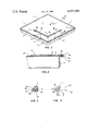
- FIG. 1 is an isometric view of an access floor panel assembly which includes a floor panel and four pairs of edge trim supports in accordance with the present invention
- FIG. 2 is a partial cross-sectional view taken along line II--II in FIG. 1;
- FIG. 3 is partial elevational view of the edge trim on the periphery of the floor panel showing an adhesive bond and a rivet after being headed;
- FIG. 4 is a partial elevational view of the edge trim on the periphery of the floor panel showing a rivet both before and after being headed.
- EDGE TRIM STRUCTURE The peripheral structure of an access floor panel which surrounds the floor tile to protect the tile from chipping, and to function as a sizing mechanism for the overall panel completing the panel assembly esthetically and functionally and capable of withstanding rough-handling and traffic wear without breaking or becoming dislodged from the panel.
- edge trim structure used to mechnically fix the edge trim structure to the panel at the corner of the edge trim or along the sides of the edge trim.
- HEADED The manufacturing process of altering the configuration of the projection, from a straight projection to a formed head, similar to cold head riveting in steel fabrication. Heading can be performed by various mechanical methods, including heat setting, ultrasonic vibration, or spin setting.
- each of edge trim structure or member 1 incorporates a continuous corner 2 which locates the joints between edge trim sections at the center of each side of a horizontally oriented panel 7 which itself is made of, for example, steel such that the continuous corner and the edge trim structure itself is located at a place far less vulnerable to in service damage and on which is mounted a horizontally oriented floor covering 17 having a peripheral edge 18.
- Four identical angle shaped and separate, horizontally planar edge trim members or structures 1 surround and enclose the peripheral edge 18 of floor covering 17 and the finished appearance of all corners 2 is consistent and uniform throughout the floor system with the top surface portion 19 of the floor covering 17 being flush with the top surface portion 20 of the edge trim structure 1.
- Each of the edge trim members or structures 1 can be affixed to the steel panel by means of an adhesive bond matrix along the peripheral portion 7A of the panel 7.
- an integral rivet 3 at the continuous corner 2 of the edge trim may be used.
- Four corner holes are punched at the corners of steel panel 7, allowing for positive positioning of each edge trim structure or member 1 and a mechanical fixing of the continuous corner 2.
- Panel 7 includes a side wall 5 having an upper peripheral flange portion 5A extending therefrom. At least one aperture 5B is formed in flange portion 5A. Peripheral portion 7A of panel 7 also includes a number of apertures 7B formed therein which are aligned with apertures 5B upon the punching of a hole through peripheral portion 7A and flange portion 5A during manufacturing.
- Rivet 3 passes down through each aligned aperture 5B and 7B and is headed in the manufacturing operation to mechanically capture the edge trim 1 in place by a headed portion 6. Since the steel panel 7 has not been deformed to capture the edge trim 1, should severe abuse make it necessary to replace the trim, such can accordingly be readily accomplished without the use of any special tools.
- a series of aligned apertures 5B and 7B are formed by punching holes in the peripheral flange 7A of the steel panel and in the flange portion 5A, and a series of intergal rivets are used as part of the edge trim structure 1 to mechanically attach the edge trim 1 to the steel panel 7 in addition to the adhesive bond 8.
- This method of assembly makes it possible, as previously noted, to locate and position the separate edge trim structures 1 most accurately, independently of other manufacturing tolerances. Since the edge trim structure 1 determines the overall panel size, this critical dimension is more tightly controlled and the series of integral rivets 3 are headed so as to form headed portion 6 in production in the same manner as a single corner rivet 3 is headed. Accordingly, should severe abuse to the panel 7 and edge trim structure 1 occur so as to make it necessary to replace one or more of the separate edge trim structures 1, such can be done without the use of any special tools.
- Each of the separate edge trim structures 1 which, in turn, each include first and second leg portions 1A, 1B, respectively, may be constructed of plastic, vinyl or similar suitable material.
Abstract
Description
Claims (14)
Priority Applications (1)
| Application Number | Priority Date | Filing Date | Title |
|---|---|---|---|
| US06/335,529 US4453365A (en) | 1981-12-29 | 1981-12-29 | Edge trim structure for access floor panel |
Applications Claiming Priority (1)
| Application Number | Priority Date | Filing Date | Title |
|---|---|---|---|
| US06/335,529 US4453365A (en) | 1981-12-29 | 1981-12-29 | Edge trim structure for access floor panel |
Publications (1)
| Publication Number | Publication Date |
|---|---|
| US4453365A true US4453365A (en) | 1984-06-12 |
Family
ID=23312160
Family Applications (1)
| Application Number | Title | Priority Date | Filing Date |
|---|---|---|---|
| US06/335,529 Expired - Lifetime US4453365A (en) | 1981-12-29 | 1981-12-29 | Edge trim structure for access floor panel |
Country Status (1)
| Country | Link |
|---|---|
| US (1) | US4453365A (en) |
Cited By (18)
| Publication number | Priority date | Publication date | Assignee | Title |
|---|---|---|---|---|
| GB2187219A (en) * | 1986-02-28 | 1987-09-03 | Mallinson Denny | Floor tile or panel with edge of base tray enfolded with edge of lid |
| EP0295801A2 (en) * | 1987-05-28 | 1988-12-21 | Thorsman & Co. (U.K.) Limited | Flooring panels |
| US4850176A (en) * | 1987-12-28 | 1989-07-25 | C-Tec, Inc. | Access floor panel with peripheral trim |
| US4934116A (en) * | 1987-01-12 | 1990-06-19 | Ole Frederiksen | Floor covering of electrically conducting type |
| US5048242A (en) * | 1990-04-04 | 1991-09-17 | C-Tec, Inc. | Access floor system with hemmed edge panel |
| US5111630A (en) * | 1987-12-28 | 1992-05-12 | C-Tec, Inc. | Access floor panel with peripheral trim |
| WO2003064786A1 (en) * | 2002-02-01 | 2003-08-07 | Kingspan Holdings (Irl) Limited | A floor panel and method for manufacturing of such panel |
| US6622443B2 (en) | 1999-05-25 | 2003-09-23 | Interface, Inc. | Trim for high pressure laminate and other decorative floor coverings |
| US6637161B1 (en) | 2000-11-28 | 2003-10-28 | Steelcase Development Corporation | Floor system |
| US6797219B1 (en) | 2000-11-28 | 2004-09-28 | Steelcase Development Corporation | Method for manufacture of floor panels |
| US20050246984A1 (en) * | 2004-04-13 | 2005-11-10 | Sam Colosimo | Modular access floor system with airseal gasket |
| US20090266019A1 (en) * | 2005-10-04 | 2009-10-29 | Mcintosh Jonathan | Modular flooring assemblies |
| US20100005757A1 (en) * | 2005-01-10 | 2010-01-14 | Collison Alan B | Snap together floor structure |
| GB2467470A (en) * | 2005-10-04 | 2010-08-04 | Comc Llc | Right-angled grout member |
| US20100275535A1 (en) * | 2009-04-29 | 2010-11-04 | John Leavitt Gard | Modular Entrance Floor System |
| US20100313509A1 (en) * | 2009-06-10 | 2010-12-16 | Mcintosh Jonathan | Medallion insert for modular flooring assemblies |
| US8782989B2 (en) | 2009-06-11 | 2014-07-22 | Comc, Llc | Narrow lined modular flooring assemblies |
| USD744119S1 (en) | 2013-10-25 | 2015-11-24 | E.M.E.H., Inc. | Portion of an entrance floor |
Citations (22)
| Publication number | Priority date | Publication date | Assignee | Title |
|---|---|---|---|---|
| US72634A (en) * | 1867-12-24 | Improved wooden chair-seat | ||
| US1851055A (en) * | 1926-08-16 | 1932-03-29 | Lyon Metal Products Inc | Table construction |
| US2925631A (en) * | 1956-05-17 | 1960-02-23 | Carpet Craftsmen Inc | Covering for the interior surfaces of buildings and method of applying same |
| US2956652A (en) * | 1958-08-15 | 1960-10-18 | Liskey Aluminum | Elevated false floor |
| US3065506A (en) * | 1956-08-13 | 1962-11-27 | John H O Neill | Pedestal panel floor |
| US3067843A (en) * | 1962-12-11 | Floor paneling arrangement | ||
| US3150748A (en) * | 1960-09-16 | 1964-09-29 | Liskey Aluminum | Elevated sectional floor |
| US3157254A (en) * | 1958-01-30 | 1964-11-17 | Floating Floors Inc | Sectional flooring |
| US3180460A (en) * | 1960-09-16 | 1965-04-27 | Liskey Aluminum | Floor panel for elevated flooring |
| US3318057A (en) * | 1964-03-24 | 1967-05-09 | Robertson Co H H | Pedestal floor construction |
| US3548559A (en) * | 1969-05-05 | 1970-12-22 | Liskey Aluminum | Floor panel |
| US3728833A (en) * | 1971-03-11 | 1973-04-24 | A Grossman | Frame construction having arcuate corners and a continuous feature strip |
| US3841682A (en) * | 1973-06-20 | 1974-10-15 | Teledyne Mid America Corp | Vehicle bumper rub strip construction |
| US3869106A (en) * | 1972-11-22 | 1975-03-04 | Stephen Gregov | Safety bumper for furniture |
| US4035967A (en) * | 1972-12-22 | 1977-07-19 | A. R. I. Propaflor Limited | Raised floor panels |
| US4074488A (en) * | 1974-06-05 | 1978-02-21 | Liskey Archectural Mfg. Inc. | Elevated floor assembly |
| US4085557A (en) * | 1976-06-01 | 1978-04-25 | James A. Tharp | Raised access floor system |
| US4142341A (en) * | 1978-01-16 | 1979-03-06 | Mult-A-Frame Corporation | Panel construction for elevated floor systems |
| US4229919A (en) * | 1979-02-12 | 1980-10-28 | Oakwood Manufacturing, Inc. | Kit of components for interconnecting structural members, and method of utilizing same |
| US4279109A (en) * | 1977-05-12 | 1981-07-21 | Madl Jr Joseph | Access floor mounting assembly |
| US4295319A (en) * | 1979-10-31 | 1981-10-20 | G. H. Products, Inc. | Floor panel |
| US4364591A (en) * | 1981-04-24 | 1982-12-21 | Chrysler Corporation | Eyelet trim strip fastening arrangement |
-
1981
- 1981-12-29 US US06/335,529 patent/US4453365A/en not_active Expired - Lifetime
Patent Citations (22)
| Publication number | Priority date | Publication date | Assignee | Title |
|---|---|---|---|---|
| US72634A (en) * | 1867-12-24 | Improved wooden chair-seat | ||
| US3067843A (en) * | 1962-12-11 | Floor paneling arrangement | ||
| US1851055A (en) * | 1926-08-16 | 1932-03-29 | Lyon Metal Products Inc | Table construction |
| US2925631A (en) * | 1956-05-17 | 1960-02-23 | Carpet Craftsmen Inc | Covering for the interior surfaces of buildings and method of applying same |
| US3065506A (en) * | 1956-08-13 | 1962-11-27 | John H O Neill | Pedestal panel floor |
| US3157254A (en) * | 1958-01-30 | 1964-11-17 | Floating Floors Inc | Sectional flooring |
| US2956652A (en) * | 1958-08-15 | 1960-10-18 | Liskey Aluminum | Elevated false floor |
| US3150748A (en) * | 1960-09-16 | 1964-09-29 | Liskey Aluminum | Elevated sectional floor |
| US3180460A (en) * | 1960-09-16 | 1965-04-27 | Liskey Aluminum | Floor panel for elevated flooring |
| US3318057A (en) * | 1964-03-24 | 1967-05-09 | Robertson Co H H | Pedestal floor construction |
| US3548559A (en) * | 1969-05-05 | 1970-12-22 | Liskey Aluminum | Floor panel |
| US3728833A (en) * | 1971-03-11 | 1973-04-24 | A Grossman | Frame construction having arcuate corners and a continuous feature strip |
| US3869106A (en) * | 1972-11-22 | 1975-03-04 | Stephen Gregov | Safety bumper for furniture |
| US4035967A (en) * | 1972-12-22 | 1977-07-19 | A. R. I. Propaflor Limited | Raised floor panels |
| US3841682A (en) * | 1973-06-20 | 1974-10-15 | Teledyne Mid America Corp | Vehicle bumper rub strip construction |
| US4074488A (en) * | 1974-06-05 | 1978-02-21 | Liskey Archectural Mfg. Inc. | Elevated floor assembly |
| US4085557A (en) * | 1976-06-01 | 1978-04-25 | James A. Tharp | Raised access floor system |
| US4279109A (en) * | 1977-05-12 | 1981-07-21 | Madl Jr Joseph | Access floor mounting assembly |
| US4142341A (en) * | 1978-01-16 | 1979-03-06 | Mult-A-Frame Corporation | Panel construction for elevated floor systems |
| US4229919A (en) * | 1979-02-12 | 1980-10-28 | Oakwood Manufacturing, Inc. | Kit of components for interconnecting structural members, and method of utilizing same |
| US4295319A (en) * | 1979-10-31 | 1981-10-20 | G. H. Products, Inc. | Floor panel |
| US4364591A (en) * | 1981-04-24 | 1982-12-21 | Chrysler Corporation | Eyelet trim strip fastening arrangement |
Cited By (33)
| Publication number | Priority date | Publication date | Assignee | Title |
|---|---|---|---|---|
| GB2187219A (en) * | 1986-02-28 | 1987-09-03 | Mallinson Denny | Floor tile or panel with edge of base tray enfolded with edge of lid |
| US4934116A (en) * | 1987-01-12 | 1990-06-19 | Ole Frederiksen | Floor covering of electrically conducting type |
| EP0295801A3 (en) * | 1987-05-28 | 1991-02-06 | Thorsman & Co. (U.K.) Limited | Flooring panels |
| EP0295801A2 (en) * | 1987-05-28 | 1988-12-21 | Thorsman & Co. (U.K.) Limited | Flooring panels |
| US5111630A (en) * | 1987-12-28 | 1992-05-12 | C-Tec, Inc. | Access floor panel with peripheral trim |
| US4850176A (en) * | 1987-12-28 | 1989-07-25 | C-Tec, Inc. | Access floor panel with peripheral trim |
| US5048242A (en) * | 1990-04-04 | 1991-09-17 | C-Tec, Inc. | Access floor system with hemmed edge panel |
| US6622443B2 (en) | 1999-05-25 | 2003-09-23 | Interface, Inc. | Trim for high pressure laminate and other decorative floor coverings |
| US6637161B1 (en) | 2000-11-28 | 2003-10-28 | Steelcase Development Corporation | Floor system |
| US6797219B1 (en) | 2000-11-28 | 2004-09-28 | Steelcase Development Corporation | Method for manufacture of floor panels |
| WO2003064786A1 (en) * | 2002-02-01 | 2003-08-07 | Kingspan Holdings (Irl) Limited | A floor panel and method for manufacturing of such panel |
| GB2399835A (en) * | 2002-02-01 | 2004-09-29 | Kingspan Holdings | A floor panel and method for manufacturing of such panel |
| GB2399835B (en) * | 2002-02-01 | 2005-10-05 | Kingspan Holdings | A floor panel and method for manufacturing of such panel |
| US20050246984A1 (en) * | 2004-04-13 | 2005-11-10 | Sam Colosimo | Modular access floor system with airseal gasket |
| US7509782B2 (en) * | 2004-04-13 | 2009-03-31 | Tate Asp Access Floors, Inc. | Metal framed floor panel having flange outward of rib with u-shaped portion of gasket over top of rib, portion of gasket between rib and flange, and convex sealing portion of gasket below flange and outward of rib |
| US20100005757A1 (en) * | 2005-01-10 | 2010-01-14 | Collison Alan B | Snap together floor structure |
| US7779602B2 (en) | 2005-01-10 | 2010-08-24 | Comc, Llc | Snap together floor structure |
| US8146319B2 (en) | 2005-10-04 | 2012-04-03 | Comc Llc | Modular flooring assemblies |
| GB2467470A (en) * | 2005-10-04 | 2010-08-04 | Comc Llc | Right-angled grout member |
| GB2467470B (en) * | 2005-10-04 | 2010-10-06 | Comc Llc | Modular flooring assemblies |
| US8631624B2 (en) | 2005-10-04 | 2014-01-21 | Comc, Llc | Modular flooring assemblies |
| US20090266019A1 (en) * | 2005-10-04 | 2009-10-29 | Mcintosh Jonathan | Modular flooring assemblies |
| US8291670B2 (en) | 2009-04-29 | 2012-10-23 | E.M.E.H., Inc. | Modular entrance floor system |
| US8601767B2 (en) | 2009-04-29 | 2013-12-10 | E.M.E.H., Inc. | Modular entrance floor system |
| US20100275535A1 (en) * | 2009-04-29 | 2010-11-04 | John Leavitt Gard | Modular Entrance Floor System |
| US8997432B2 (en) | 2009-04-29 | 2015-04-07 | E.M.E.H., Inc. | Modular entrance floor system |
| US8230654B2 (en) | 2009-06-10 | 2012-07-31 | Comc, Llc | Medallion insert for modular flooring assemblies |
| US20100313509A1 (en) * | 2009-06-10 | 2010-12-16 | Mcintosh Jonathan | Medallion insert for modular flooring assemblies |
| US8458974B2 (en) | 2009-06-10 | 2013-06-11 | Comc, Llc | Medallion insert for modular flooring assemblies |
| US8782989B2 (en) | 2009-06-11 | 2014-07-22 | Comc, Llc | Narrow lined modular flooring assemblies |
| USD744119S1 (en) | 2013-10-25 | 2015-11-24 | E.M.E.H., Inc. | Portion of an entrance floor |
| US9340983B2 (en) | 2013-10-25 | 2016-05-17 | E.M.E.H., Inc. | Entrance floor system |
| US10722991B2 (en) | 2013-10-25 | 2020-07-28 | E.M.E.H., Inc. | Entrance floor system |
Similar Documents
| Publication | Publication Date | Title |
|---|---|---|
| US4453365A (en) | Edge trim structure for access floor panel | |
| WO2005080736A1 (en) | Devices, systems and methods for manufacturing and installing modular window trim | |
| EP1650369B1 (en) | Sound absorbing panel | |
| JP3602536B2 (en) | Method for interconnecting wallboards and novel wall elements | |
| CA1162017A (en) | Coreless hung panel assembly | |
| US4507009A (en) | Means and method for preventing cracks from developing in an industrialized house | |
| AU4492285A (en) | Panelling system and panelling clips for the same | |
| JP2640800B2 (en) | Metal gasket bead forming mold | |
| JP2817027B2 (en) | Double floor floor panel support equipment | |
| JP2991267B2 (en) | How to assemble the elevator car side plate | |
| JP2567088Y2 (en) | Exterior wall structure | |
| JPH0329466Y2 (en) | ||
| JP2023158900A (en) | Curtain wall fixation structure and curtain wall fixation method | |
| KR940007060Y1 (en) | Floorings | |
| JPS592265Y2 (en) | pulls for fittings | |
| JP2508261Y2 (en) | Joint structure and joint material | |
| JPS596984B2 (en) | Installation structure of external wall panels | |
| JPH0810120Y2 (en) | Veneer | |
| JP2541989Y2 (en) | Communication facility housing box | |
| EP0863405B1 (en) | Mounting plate for electromagnetic-wave absorbers | |
| JP3050822B2 (en) | Joint hardware for construction | |
| JPH0727287Y2 (en) | ALC outer wall panel | |
| JPH0654829U (en) | Stone fittings for attaching stone materials to the building surface | |
| JP2511641Y2 (en) | Field board corner decoration | |
| JPH0326803Y2 (en) |
Legal Events
| Date | Code | Title | Description |
|---|---|---|---|
| AS | Assignment |
Owner name: TATE ARCHITECTURAL PRODCUTS, INC., 7510 MONTEVIDEO Free format text: ASSIGNMENT OF ASSIGNORS INTEREST.;ASSIGNOR:GLADDEN, ROBERT S.;REEL/FRAME:004202/0549 Effective date: 19811222 |
|
| FPAY | Fee payment |
Year of fee payment: 4 |
|
| FEPP | Fee payment procedure |
Free format text: PETITION RELATED TO MAINTENANCE FEES FILED (ORIGINAL EVENT CODE: PMFP); ENTITY STATUS OF PATENT OWNER: LARGE ENTITY |
|
| FEPP | Fee payment procedure |
Free format text: PETITION RELATED TO MAINTENANCE FEES FILED (ORIGINAL EVENT CODE: PMFP); ENTITY STATUS OF PATENT OWNER: LARGE ENTITY |
|
| FEPP | Fee payment procedure |
Free format text: PETITION RELATED TO MAINTENANCE FEES DENIED/DISMISSED (ORIGINAL EVENT CODE: PMFD); ENTITY STATUS OF PATENT OWNER: LARGE ENTITY |
|
| REMI | Maintenance fee reminder mailed | ||
| SULP | Surcharge for late payment | ||
| FP | Lapsed due to failure to pay maintenance fee |
Effective date: 19920614 |
|
| FPAY | Fee payment |
Year of fee payment: 8 |
|
| SULP | Surcharge for late payment | ||
| STCF | Information on status: patent grant |
Free format text: PATENTED CASE |
|
| DP | Notification of acceptance of delayed payment of maintenance fee | ||
| AS | Assignment |
Owner name: MERCANTILE-SAFE DEPOSIT AND TRUST COMPANY, MARYLAN Free format text: ASSIGNMENT OF ASSIGNORS INTEREST;ASSIGNOR:TATE ACCESS FLOORS, INC. (A CORP. OF MARYLAND);REEL/FRAME:007329/0438 Effective date: 19941230 |
|
| FPAY | Fee payment |
Year of fee payment: 12 |
|
| AS | Assignment |
Owner name: TATE ACCESS FLOORS LEASING, INC., MARYLAND Free format text: ASSIGNMENT OF ASSIGNORS INTEREST;ASSIGNOR:TATE ACCESS FLOORS, INC.;REEL/FRAME:012607/0424 Effective date: 20020214 |