US4453836A - Sealed hard-rock drill bit - Google Patents
Sealed hard-rock drill bit Download PDFInfo
- Publication number
- US4453836A US4453836A US06/297,944 US29794481A US4453836A US 4453836 A US4453836 A US 4453836A US 29794481 A US29794481 A US 29794481A US 4453836 A US4453836 A US 4453836A
- Authority
- US
- United States
- Prior art keywords
- disposed
- seal
- receiving groove
- cutter
- journal
- Prior art date
- Legal status (The legal status is an assumption and is not a legal conclusion. Google has not performed a legal analysis and makes no representation as to the accuracy of the status listed.)
- Expired - Fee Related
Links
Images


Classifications
-
- E—FIXED CONSTRUCTIONS
- E21—EARTH DRILLING; MINING
- E21B—EARTH DRILLING, e.g. DEEP DRILLING; OBTAINING OIL, GAS, WATER, SOLUBLE OR MELTABLE MATERIALS OR A SLURRY OF MINERALS FROM WELLS
- E21B10/00—Drill bits
- E21B10/08—Roller bits
- E21B10/22—Roller bits characterised by bearing, lubrication or sealing details
- E21B10/25—Roller bits characterised by bearing, lubrication or sealing details characterised by sealing details
-
- E—FIXED CONSTRUCTIONS
- E21—EARTH DRILLING; MINING
- E21B—EARTH DRILLING, e.g. DEEP DRILLING; OBTAINING OIL, GAS, WATER, SOLUBLE OR MELTABLE MATERIALS OR A SLURRY OF MINERALS FROM WELLS
- E21B10/00—Drill bits
- E21B10/08—Roller bits
- E21B10/22—Roller bits characterised by bearing, lubrication or sealing details
- E21B10/24—Roller bits characterised by bearing, lubrication or sealing details characterised by lubricating details
Definitions
- This invention relates generally to drill bits for providing holes in earth formations for wells, blast holes and the like. It is more particularly directed to rotary drill bits for use in relatively hard earth formations which may also be abrasive in nature, such as taconite or the like.
- One of the problems associated with drill bits of the class of drilling activities in which my invention finds substantial advantageous use, is concerned with economics, not only in the cost of labor for running drilling equipment, but in the cost of the drilling equipment itself, including the expendable drilling bits.
- My invention provides an improved economic advantage, when considering the factors set forth above, and others, in that it provides a substantially longer life, may be easier to fabricate of available components and is reliable in operation.
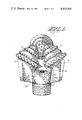
- FIG. 1 is a perspective sketch of a rotary drill bit of the invention
- FIG. 2 is an enlarged fragmentary view of a portion of the illustration of FIG. 1, partly in section, showing a first embodiment of my invention.
- FIG. 3 is a similarly enlarged, fragmentary view, partly in section, of a portion of FIG. 1 showing a second embodiment of my invention.
- a rotary drill bit of the class to which my invention pertains is indicated generally by reference character 10 and includes a body portion 11, having a top threaded portion for threaded connection to a drill string pipe.
- Body 11 is comprised of a plurality of legs 12 that may conveniently be fabricated in sections and then joined together, as by welding, to form body 11, and a like plurality of rotary cone shaped cutters 13 rotatably disposed on journals 15 at the lower inner ends of legs 12.
- Legs 12 because of their orientation in an assembled bit, may be thought of as having a top outer end and a journal 15 at the lower inner end in the sense that the lower journal end is directed inwardly of the periphery of the body 11 of a drill bit 10.
- the lower, or inner end of journals 15 is indicated by reference character 16 and it may be seen that the axis of inner end of journals 15 is preferably disposed, when assembled into a body 11, at an angle of 36° to 45° with respect to a horizontal plane that is perpendicular to the vertical axis of body 11 and thereby to a drill stem to which drill bit 10 may be connected.
- journal 15 Proceeding upwardly and outwardly from inner end 16 on journals 15, there is shown an axially extending roller bearing race groove 17, a roller bearing race surface 33, extending radially of the axis of inner end 16, a ball bearing retainer race groove 18, having a radius related to the radius of ball bearings to be positioned therein, an axially extending roller bearing race surface 19, a first seal groove 20 and a second seal groove 21.
- journals 15 are circular in cross-section and symmetrical about the center axis shown.
- Legs 12 are also provided with an air duct 22 that extends from the top outer portion of body 11, for receiving air from inside of the drill stem through the top threaded portion of body 11, to the side skirt portions on legs 12. Air duct 22 is also shown connected to a branch air duct 23.
- Legs 12 are also shown provided with an outer stabilizer portion 25 that may be further provided with carbide inserts 26 and includes a downwardly extending skirt portion 27.
- a lubrication duct 28 extends inwardly through journals 15 to the lower inner end and is provided with a lubrication fitting 29 appropriate for a suitable lubricant to be introduced into a completed drill bit 10.
- a lubrication relief duct 30 is shown extending from the inner end of journals 15 to seal groove 21.
- a pressure relief valve 31 is shown disposed at an appropriate location in relief duct 30.
- Cones 13 are provided with an interior recess indicated generally by reference character 40.
- Recess 40 is shown having an inner end 41, an axially extending roller bearing race surface 42, a radially extending roller bearing race surface 43, a ball bearing retainer race-groove 44, an axially extending roller race groove 45, an axially extending seal surface 46 and a radially extending outwardly opening air groove 47 adjacent the top or outer end of recess 40.
- a plurality of anti-friction roller and ball bearings are disposed intermediate the complementary configured and disposed bearing grooves and surfaces described above in connection with journals 15 and cones 13 and include a plurality of axial roller bearing members 50, a plurality of radially disposed thrust roller bearing members 51, a plurality of retainer-ball bearing members 52 and a plurality of roller bearing members 53.
- Thrust roller bearings 51 of FIG. 2 are shown having a tapered configuration and it may be noted that a floating spacer ring 54 is disposed at the radially inward periphery of the rollers and that the radially outward ends of rollers 51 are provided with a convex configuration.
- seal 60 which may be described as an inner seal and which is preferably comprised of an elastomer resilient material that is slightly compressed when in the assembled position shown so that its outer peripheral surface is in sliding frictional and sealing engagement with surface 46 on cones 13 and the inner portions provide a sealing non-rotating contact with the bottom and sides of seal groove 20 in journals 15.
- the outer seal is indicated generally by reference character 64 and is preferably comprised of a continuous metallic ring of material that is in non-sliding engagement with seal surface 46 on cones 13 and is in sliding frictional engagement with the sides of seal groove 21 in journals 15. It may thus be observed and understood that seal 60 provides a form of pressure responsive seal while seal 64 provides a labyrinth type of seal.
- seals 60 and 64 serves to prevent the escape of lubricant from the inside of cones 13 and the inner ends of journals 15 while providing an adequate barrier to prevent the entry of any foreign material, such as drilling debris, into the lubricant containing portions of journals 15 and cones 13.
- FIG. 3 illustrates a further embodiment of my invention in which inner seal 60 is shown comprised of a large O-ring 61 that extends outwardly of inner groove 20 and a pair of smaller O-rings 62 and 63 that are disposed adjacent the bottom sides of groove 20. O-rings 62 and 63 may be of lesser hardness with respect to O-ring 61. FIG. 3 further indicates a relocation of lubricant fitting 29 for adding lubricant to the inside of cones 13, as may be required.
- radius of ball-retainer race groove 18 in journals 15 may be related to the radius of retainer-ball bearings 52 whereby the radius of groove 18 is 0.52 times the radius of retainer-balls 52.
- a drill bit 10 is assembled to the end of a drill string.
- Lubrication is applied to lubricant fitting 29 disposed in air duct 22, extending through the side of legs 12, and is supplied to the interior of cones 13 around journals 15 until the pressure relief valve allows lubricant to flow through duct 30 and seal groove 21 and to appear at the outer periphery of recess 40 in cones 13 adjacent legs 12.
- the appropriate drive mechanism for the rotary drill stem is started and air is supplied through the interior of the drill stem to air ducts 22 in journals 12.
- tapered thrust roller bearings 51 illustrated in FIG. 2 will provide a "true-line" rolling contact that may contribute further to the longevity of the drill bit under working conditions.
- the larger radius of ball bearing retainer race groove 18 over the size of retainer ball bearings 52 provides a further longevity of effective life of drill bit 10.
Abstract
Description
______________________________________
U.S. Pat. No. Inventor     Date of Issue
______________________________________
3,193,028     Radzimovsky  7/6/65
3,251,634     Dareing      5/17/66
3,344,870     Morris       10/3/67
3,461,983     Hudson et al 8/19/69
3,572,452     Winberg      3/30/71
3,628,616     Neilson      12/21/71
3,866,695     Jackson      2/18/75
3,921,735     Dysart       11/25/75
3,952,815     Dysart       4/27/76
2,126,035     Reed         8/9/38
2,126,040     Reed         8/9/38
2,177,333     Reed         10/24/39
2,673,128     Reed         3/23/54
2,664,322     Boice        12/29/53
2,690,935     Alexander    10/5/54
2,719,026     Boice        9/27/55
4,013,325     Rear         3/22/77
4,140,189     Garner       2/20/79
4,183,417     Levefelt     1/15/80
______________________________________
Claims (6)
Priority Applications (1)
| Application Number | Priority Date | Filing Date | Title |
|---|---|---|---|
| US06/297,944 US4453836A (en) | 1981-08-31 | 1981-08-31 | Sealed hard-rock drill bit |
Applications Claiming Priority (1)
| Application Number | Priority Date | Filing Date | Title |
|---|---|---|---|
| US06/297,944 US4453836A (en) | 1981-08-31 | 1981-08-31 | Sealed hard-rock drill bit |
Publications (1)
| Publication Number | Publication Date |
|---|---|
| US4453836A true US4453836A (en) | 1984-06-12 |
Family
ID=23148366
Family Applications (1)
| Application Number | Title | Priority Date | Filing Date |
|---|---|---|---|
| US06/297,944 Expired - Fee Related US4453836A (en) | 1981-08-31 | 1981-08-31 | Sealed hard-rock drill bit |
Country Status (1)
| Country | Link |
|---|---|
| US (1) | US4453836A (en) |
Cited By (28)
| Publication number | Priority date | Publication date | Assignee | Title |
|---|---|---|---|---|
| US4981182A (en) * | 1990-01-26 | 1991-01-01 | Dresser Industries, Inc. | Sealed rotary blast hole drill bit utilizing air pressure for seal protection |
| EP0415519A1 (en) * | 1989-07-19 | 1991-03-06 | Intevep, S.A. | Dual seal system for rotary drill bit |
| US5027911A (en) * | 1989-11-02 | 1991-07-02 | Dresser Industries, Inc. | Double seal with lubricant gap between seals for sealed rotary drill bits |
| US5441120A (en) * | 1994-08-31 | 1995-08-15 | Dresser Industries, Inc. | Roller cone rock bit having a sealing system with double elastomer seals |
| US5513715A (en) * | 1994-08-31 | 1996-05-07 | Dresser Industries, Inc. | Flat seal for a roller cone rock bit |
| US5513711A (en) * | 1994-08-31 | 1996-05-07 | Williams; Mark E. | Sealed and lubricated rotary cone drill bit having improved seal protection |
| US5636700A (en) * | 1995-01-03 | 1997-06-10 | Dresser Industries, Inc. | Roller cone rock bit having improved cutter gauge face surface compacts and a method of construction |
| US5709278A (en) * | 1996-01-22 | 1998-01-20 | Dresser Industries, Inc. | Rotary cone drill bit with contoured inserts and compacts |
| US5722497A (en) * | 1996-03-21 | 1998-03-03 | Dresser Industries, Inc. | Roller cone gage surface cutting elements with multiple ultra hard cutting surfaces |
| US6033117A (en) * | 1995-12-19 | 2000-03-07 | Smith International, Inc. | Sealed bearing drill bit with dual-seal configuration |
| US6092611A (en) * | 1997-05-28 | 2000-07-25 | Dresser Industries, Inc. | Encapsulated elastomeric relief valve |
| US6116357A (en) * | 1996-09-09 | 2000-09-12 | Smith International, Inc. | Rock drill bit with back-reaming protection |
| US6254275B1 (en) | 1995-12-19 | 2001-07-03 | Smith International, Inc. | Sealed bearing drill bit with dual-seal configuration and fluid-cleaning capability |
| US6264367B1 (en) | 1995-12-19 | 2001-07-24 | Smith International, Inc. | Dual-seal drill bit with fluid cleaning capability |
| US6311789B1 (en) * | 1998-07-17 | 2001-11-06 | Halliburton Energy Services, Inc. | Bit breakers, bits, systems, and methods with improved makeup/breakout engagement |
| GB2380500A (en) * | 2001-10-05 | 2003-04-09 | Varel International Inc | Rotary cone bit with thrust bearing |
| US6595304B2 (en) * | 2000-06-29 | 2003-07-22 | Kingdream Public Limited Company | Roller bit parallel inlayed compacts |
| US6619412B2 (en) | 1996-09-09 | 2003-09-16 | Smith International, Inc. | Protected lubricant reservoir for sealed earth boring drill bit |
| EP1852618A2 (en) * | 2006-05-04 | 2007-11-07 | IMO Momentenlager GmbH | Rolling bearing device |
| US20080041630A1 (en) * | 2006-08-18 | 2008-02-21 | Atlas Copco Secoroc Llc | Earth bit having a pressure relief valve |
| US20110024197A1 (en) * | 2009-07-31 | 2011-02-03 | Smith International, Inc. | High shear roller cone drill bits |
| US20130153304A1 (en) * | 2011-12-14 | 2013-06-20 | Halliburton Energy Services, Inc. | Floating plug pressure equalization in oilfield drill bits |
| US20140238742A1 (en) * | 2013-02-27 | 2014-08-28 | Skf Lubrication Systems Germany Ag | Device for supplying lubricant to a lubrication point in a machine |
| US8961019B2 (en) | 2011-05-10 | 2015-02-24 | Smith International, Inc. | Flow control through thrust bearing assembly |
| US9010448B2 (en) | 2011-04-12 | 2015-04-21 | Halliburton Energy Services, Inc. | Safety valve with electrical actuator and tubing pressure balancing |
| US9068425B2 (en) | 2011-04-12 | 2015-06-30 | Halliburton Energy Services, Inc. | Safety valve with electrical actuator and tubing pressure balancing |
| US9574405B2 (en) | 2005-09-21 | 2017-02-21 | Smith International, Inc. | Hybrid disc bit with optimized PDC cutter placement |
| US10024107B2 (en) | 2012-12-14 | 2018-07-17 | Epiroc Drilling Tools Llc | Rotary drill bit |
Citations (21)
| Publication number | Priority date | Publication date | Assignee | Title |
|---|---|---|---|---|
| US2126035A (en) * | 1936-11-27 | 1938-08-09 | Chicago Pneumatic Tool Co | Earth boring bit |
| US2126040A (en) * | 1937-05-04 | 1938-08-09 | Chicago Pneumatic Tool Co | Roller cutter organization for earth boring drills |
| US2177333A (en) * | 1938-02-11 | 1939-10-24 | Chicago Pneumatic Tool Co | Roller cutter and spindle assembly for earth boring drills |
| US2664322A (en) * | 1950-10-09 | 1953-12-29 | Reed Roller Bit Co | Roller bit |
| US2673128A (en) * | 1949-10-08 | 1954-03-23 | Clarence E Reed | Earth-boring drill |
| US2690935A (en) * | 1949-07-13 | 1954-10-05 | George E Failing Company | Drill bit |
| US2719026A (en) * | 1952-04-28 | 1955-09-27 | Reed Roller Bit Co | Earth boring drill |
| US3193028A (en) * | 1962-09-26 | 1965-07-06 | Exxon Production Research Co | Rotary drill bit |
| US3251634A (en) * | 1963-07-01 | 1966-05-17 | Exxon Production Research Co | Drill bit bearing lubricator |
| US3344870A (en) * | 1965-03-19 | 1967-10-03 | Hughes Tool Co | Reamer for jet piercer |
| US3461983A (en) * | 1967-06-28 | 1969-08-19 | Dresser Ind | Cutting tool having hard insert in hole surrounded by hard facing |
| US3572452A (en) * | 1969-04-16 | 1971-03-30 | Dougles F Winberg | Rolling cutter and seals therefor |
| US3628616A (en) * | 1969-12-18 | 1971-12-21 | Smith International | Drilling bit with integral stabilizer |
| US3866695A (en) * | 1974-07-01 | 1975-02-18 | Dresser Ind | Bearing Cavity Pressure Maintenance Device For Sealed Bearing Rock Bit |
| US3921735A (en) * | 1975-02-27 | 1975-11-25 | Dresser Ind | Rotary rock bit with cone mouth air screen |
| US3952815A (en) * | 1975-03-24 | 1976-04-27 | Dresser Industries, Inc. | Land erosion protection on a rock cutter |
| US4013325A (en) * | 1974-09-04 | 1977-03-22 | Ian Graeme Rear | Drill rod stabilizing tool |
| US4102419A (en) * | 1976-05-10 | 1978-07-25 | Klima Frank J | Rolling cutter drill bit with annular seal rings |
| US4140189A (en) * | 1977-06-06 | 1979-02-20 | Smith International, Inc. | Rock bit with diamond reamer to maintain gage |
| US4183417A (en) * | 1977-04-01 | 1980-01-15 | Sandvik Ab | Roller bit seal excluded from cuttings by air discharge |
| US4284310A (en) * | 1978-09-05 | 1981-08-18 | Sandvik Ab | Rotary drill bit |
-
1981
- 1981-08-31 US US06/297,944 patent/US4453836A/en not_active Expired - Fee Related
Patent Citations (21)
| Publication number | Priority date | Publication date | Assignee | Title |
|---|---|---|---|---|
| US2126035A (en) * | 1936-11-27 | 1938-08-09 | Chicago Pneumatic Tool Co | Earth boring bit |
| US2126040A (en) * | 1937-05-04 | 1938-08-09 | Chicago Pneumatic Tool Co | Roller cutter organization for earth boring drills |
| US2177333A (en) * | 1938-02-11 | 1939-10-24 | Chicago Pneumatic Tool Co | Roller cutter and spindle assembly for earth boring drills |
| US2690935A (en) * | 1949-07-13 | 1954-10-05 | George E Failing Company | Drill bit |
| US2673128A (en) * | 1949-10-08 | 1954-03-23 | Clarence E Reed | Earth-boring drill |
| US2664322A (en) * | 1950-10-09 | 1953-12-29 | Reed Roller Bit Co | Roller bit |
| US2719026A (en) * | 1952-04-28 | 1955-09-27 | Reed Roller Bit Co | Earth boring drill |
| US3193028A (en) * | 1962-09-26 | 1965-07-06 | Exxon Production Research Co | Rotary drill bit |
| US3251634A (en) * | 1963-07-01 | 1966-05-17 | Exxon Production Research Co | Drill bit bearing lubricator |
| US3344870A (en) * | 1965-03-19 | 1967-10-03 | Hughes Tool Co | Reamer for jet piercer |
| US3461983A (en) * | 1967-06-28 | 1969-08-19 | Dresser Ind | Cutting tool having hard insert in hole surrounded by hard facing |
| US3572452A (en) * | 1969-04-16 | 1971-03-30 | Dougles F Winberg | Rolling cutter and seals therefor |
| US3628616A (en) * | 1969-12-18 | 1971-12-21 | Smith International | Drilling bit with integral stabilizer |
| US3866695A (en) * | 1974-07-01 | 1975-02-18 | Dresser Ind | Bearing Cavity Pressure Maintenance Device For Sealed Bearing Rock Bit |
| US4013325A (en) * | 1974-09-04 | 1977-03-22 | Ian Graeme Rear | Drill rod stabilizing tool |
| US3921735A (en) * | 1975-02-27 | 1975-11-25 | Dresser Ind | Rotary rock bit with cone mouth air screen |
| US3952815A (en) * | 1975-03-24 | 1976-04-27 | Dresser Industries, Inc. | Land erosion protection on a rock cutter |
| US4102419A (en) * | 1976-05-10 | 1978-07-25 | Klima Frank J | Rolling cutter drill bit with annular seal rings |
| US4183417A (en) * | 1977-04-01 | 1980-01-15 | Sandvik Ab | Roller bit seal excluded from cuttings by air discharge |
| US4140189A (en) * | 1977-06-06 | 1979-02-20 | Smith International, Inc. | Rock bit with diamond reamer to maintain gage |
| US4284310A (en) * | 1978-09-05 | 1981-08-18 | Sandvik Ab | Rotary drill bit |
Cited By (37)
| Publication number | Priority date | Publication date | Assignee | Title |
|---|---|---|---|---|
| EP0415519A1 (en) * | 1989-07-19 | 1991-03-06 | Intevep, S.A. | Dual seal system for rotary drill bit |
| AU632588B2 (en) * | 1989-07-19 | 1993-01-07 | Intevep, S.A. | Improved rotary drill bits |
| US5027911A (en) * | 1989-11-02 | 1991-07-02 | Dresser Industries, Inc. | Double seal with lubricant gap between seals for sealed rotary drill bits |
| US4981182A (en) * | 1990-01-26 | 1991-01-01 | Dresser Industries, Inc. | Sealed rotary blast hole drill bit utilizing air pressure for seal protection |
| US5441120A (en) * | 1994-08-31 | 1995-08-15 | Dresser Industries, Inc. | Roller cone rock bit having a sealing system with double elastomer seals |
| WO1996007010A1 (en) * | 1994-08-31 | 1996-03-07 | Dresser Industries, Inc. | Roller cone rock bit having a sealing system with double elastomer seals |
| US5513715A (en) * | 1994-08-31 | 1996-05-07 | Dresser Industries, Inc. | Flat seal for a roller cone rock bit |
| US5513711A (en) * | 1994-08-31 | 1996-05-07 | Williams; Mark E. | Sealed and lubricated rotary cone drill bit having improved seal protection |
| US5636700A (en) * | 1995-01-03 | 1997-06-10 | Dresser Industries, Inc. | Roller cone rock bit having improved cutter gauge face surface compacts and a method of construction |
| US6033117A (en) * | 1995-12-19 | 2000-03-07 | Smith International, Inc. | Sealed bearing drill bit with dual-seal configuration |
| US6254275B1 (en) | 1995-12-19 | 2001-07-03 | Smith International, Inc. | Sealed bearing drill bit with dual-seal configuration and fluid-cleaning capability |
| US6264367B1 (en) | 1995-12-19 | 2001-07-24 | Smith International, Inc. | Dual-seal drill bit with fluid cleaning capability |
| US5709278A (en) * | 1996-01-22 | 1998-01-20 | Dresser Industries, Inc. | Rotary cone drill bit with contoured inserts and compacts |
| US5722497A (en) * | 1996-03-21 | 1998-03-03 | Dresser Industries, Inc. | Roller cone gage surface cutting elements with multiple ultra hard cutting surfaces |
| US6116357A (en) * | 1996-09-09 | 2000-09-12 | Smith International, Inc. | Rock drill bit with back-reaming protection |
| US6619412B2 (en) | 1996-09-09 | 2003-09-16 | Smith International, Inc. | Protected lubricant reservoir for sealed earth boring drill bit |
| US6092611A (en) * | 1997-05-28 | 2000-07-25 | Dresser Industries, Inc. | Encapsulated elastomeric relief valve |
| US6311789B1 (en) * | 1998-07-17 | 2001-11-06 | Halliburton Energy Services, Inc. | Bit breakers, bits, systems, and methods with improved makeup/breakout engagement |
| US6595304B2 (en) * | 2000-06-29 | 2003-07-22 | Kingdream Public Limited Company | Roller bit parallel inlayed compacts |
| GB2380500A (en) * | 2001-10-05 | 2003-04-09 | Varel International Inc | Rotary cone bit with thrust bearing |
| US9574405B2 (en) | 2005-09-21 | 2017-02-21 | Smith International, Inc. | Hybrid disc bit with optimized PDC cutter placement |
| EP1852618A2 (en) * | 2006-05-04 | 2007-11-07 | IMO Momentenlager GmbH | Rolling bearing device |
| EP1852618A3 (en) * | 2006-05-04 | 2012-06-06 | IMO Momentenlager GmbH | Rolling bearing device |
| US20080041630A1 (en) * | 2006-08-18 | 2008-02-21 | Atlas Copco Secoroc Llc | Earth bit having a pressure relief valve |
| US7975782B2 (en) | 2006-08-18 | 2011-07-12 | Atlas Copco Secoroc Llc | Earth bit having a pressure relief valve |
| US20110024197A1 (en) * | 2009-07-31 | 2011-02-03 | Smith International, Inc. | High shear roller cone drill bits |
| US8672060B2 (en) * | 2009-07-31 | 2014-03-18 | Smith International, Inc. | High shear roller cone drill bits |
| US9068425B2 (en) | 2011-04-12 | 2015-06-30 | Halliburton Energy Services, Inc. | Safety valve with electrical actuator and tubing pressure balancing |
| US9010448B2 (en) | 2011-04-12 | 2015-04-21 | Halliburton Energy Services, Inc. | Safety valve with electrical actuator and tubing pressure balancing |
| US9574423B2 (en) | 2011-04-12 | 2017-02-21 | Halliburton Energy Services, Inc. | Safety valve with electrical actuator and tubing pressure balancing |
| US8961019B2 (en) | 2011-05-10 | 2015-02-24 | Smith International, Inc. | Flow control through thrust bearing assembly |
| US8800689B2 (en) * | 2011-12-14 | 2014-08-12 | Halliburton Energy Services, Inc. | Floating plug pressure equalization in oilfield drill bits |
| US9359822B2 (en) | 2011-12-14 | 2016-06-07 | Halliburton Energy Services, Inc. | Floating plug pressure equalization in oilfield drill bits |
| US20130153304A1 (en) * | 2011-12-14 | 2013-06-20 | Halliburton Energy Services, Inc. | Floating plug pressure equalization in oilfield drill bits |
| US10024107B2 (en) | 2012-12-14 | 2018-07-17 | Epiroc Drilling Tools Llc | Rotary drill bit |
| US20140238742A1 (en) * | 2013-02-27 | 2014-08-28 | Skf Lubrication Systems Germany Ag | Device for supplying lubricant to a lubrication point in a machine |
| US9938866B2 (en) * | 2013-02-27 | 2018-04-10 | Skf Lubrication Systems Germany Ag | Device for supplying lubricant to a lubrication point in a machine |
Similar Documents
| Publication | Publication Date | Title |
|---|---|---|
| US4453836A (en) | Sealed hard-rock drill bit | |
| US6513607B2 (en) | Metal-face-seal rock bit | |
| US6026917A (en) | Earth-boring bit with improved bearing seal | |
| US4179003A (en) | Seal for a rolling cone cutter earth boring bit | |
| US3765495A (en) | Drill bit seals | |
| US3990525A (en) | Sealing system for a rotary rock bit | |
| US5513711A (en) | Sealed and lubricated rotary cone drill bit having improved seal protection | |
| US6405811B1 (en) | Solid lubricant for air cooled drill bit and method of drilling | |
| CA1081686A (en) | Drill bit air clearing system | |
| CA1095503A (en) | Cutter actuated rock bit lubrication system | |
| US7347290B2 (en) | Multi-part energizer for mechanical seal assembly | |
| US4098358A (en) | Drill bit with hard-faced bearing surfaces | |
| JPS6361472B2 (en) | ||
| US3389760A (en) | Rolling cutters for rock formations mounted on simple beam bearings | |
| CA1041476A (en) | Roller cutter drill bit | |
| US7000712B2 (en) | Bearing seal | |
| US4253710A (en) | High temperature sealing system for a rotary rock bit | |
| US5381868A (en) | Sealed bearing roller reamer | |
| US4252330A (en) | Symmetrical seal for a rolling cone cutter earth boring bit | |
| US4613004A (en) | Earth boring bit with labyrinth seal protector | |
| US4178045A (en) | Abrasion resistant bearing seal | |
| US5655611A (en) | Earth-boring bit with improved bearing seal | |
| US2894727A (en) | Drilling bit | |
| US4330158A (en) | Rotary rock bit with improved thrust flange | |
| CA2019460A1 (en) | Rotary drill bits |
Legal Events
| Date | Code | Title | Description |
|---|---|---|---|
| AS | Assignment |
Owner name: STURM WARREN A. 7900 XERXES AVENUE SOUTH, MINNEAPO Free format text: ASSIGNMENT OF A PART OF ASSIGNORS INTEREST;ASSIGNORS:KLIMA FRANK J.;STURM, WARREN A.;REEL/FRAME:004449/0115 Effective date: 19850723 |
|
| FPAY | Fee payment |
Year of fee payment: 4 |
|
| FEPP | Fee payment procedure |
Free format text: PAYOR NUMBER ASSIGNED (ORIGINAL EVENT CODE: ASPN); ENTITY STATUS OF PATENT OWNER: SMALL ENTITY |
|
| FPAY | Fee payment |
Year of fee payment: 8 |
|
| REMI | Maintenance fee reminder mailed | ||
| LAPS | Lapse for failure to pay maintenance fees | ||
| FP | Lapsed due to failure to pay maintenance fee |
Effective date: 19960612 |
|
| STCH | Information on status: patent discontinuation |
Free format text: PATENT EXPIRED DUE TO NONPAYMENT OF MAINTENANCE FEES UNDER 37 CFR 1.362 |