US4484333A - Coupled waveguide freespace laser - Google Patents
Coupled waveguide freespace laser Download PDFInfo
- Publication number
- US4484333A US4484333A US06/348,566 US34856682A US4484333A US 4484333 A US4484333 A US 4484333A US 34856682 A US34856682 A US 34856682A US 4484333 A US4484333 A US 4484333A
- Authority
- US
- United States
- Prior art keywords
- cavity
- waveguide
- laser
- reflective element
- optical
- Prior art date
- Legal status (The legal status is an assumption and is not a legal conclusion. Google has not performed a legal analysis and makes no representation as to the accuracy of the status listed.)
- Expired - Fee Related
Links
Images
Classifications
-
- H—ELECTRICITY
- H01—ELECTRIC ELEMENTS
- H01S—DEVICES USING THE PROCESS OF LIGHT AMPLIFICATION BY STIMULATED EMISSION OF RADIATION [LASER] TO AMPLIFY OR GENERATE LIGHT; DEVICES USING STIMULATED EMISSION OF ELECTROMAGNETIC RADIATION IN WAVE RANGES OTHER THAN OPTICAL
- H01S3/00—Lasers, i.e. devices using stimulated emission of electromagnetic radiation in the infrared, visible or ultraviolet wave range
- H01S3/10—Controlling the intensity, frequency, phase, polarisation or direction of the emitted radiation, e.g. switching, gating, modulating or demodulating
- H01S3/106—Controlling the intensity, frequency, phase, polarisation or direction of the emitted radiation, e.g. switching, gating, modulating or demodulating by controlling devices placed within the cavity
- H01S3/107—Controlling the intensity, frequency, phase, polarisation or direction of the emitted radiation, e.g. switching, gating, modulating or demodulating by controlling devices placed within the cavity using electro-optic devices, e.g. exhibiting Pockels or Kerr effect
-
- H—ELECTRICITY
- H01—ELECTRIC ELEMENTS
- H01S—DEVICES USING THE PROCESS OF LIGHT AMPLIFICATION BY STIMULATED EMISSION OF RADIATION [LASER] TO AMPLIFY OR GENERATE LIGHT; DEVICES USING STIMULATED EMISSION OF ELECTROMAGNETIC RADIATION IN WAVE RANGES OTHER THAN OPTICAL
- H01S3/00—Lasers, i.e. devices using stimulated emission of electromagnetic radiation in the infrared, visible or ultraviolet wave range
- H01S3/05—Construction or shape of optical resonators; Accommodation of active medium therein; Shape of active medium
- H01S3/08—Construction or shape of optical resonators or components thereof
- H01S3/081—Construction or shape of optical resonators or components thereof comprising three or more reflectors
- H01S3/082—Construction or shape of optical resonators or components thereof comprising three or more reflectors defining a plurality of resonators, e.g. for mode selection or suppression
Definitions
- the field of the invention is that of a waveguide laser having an electro-optical modulator located in a cavity coupled to the cavity having optical gain.
- U.S. Pat. No. 4,176,327 issued Nov. 27, 1979 to Robert J. Wayne et al, discloses a laser having an electro-optical modulator together with a polarizing coupler, in which the modulator Q-switches the laser by converting linearly polarized light to circularly polarized light, then reconverting that circularly polarized light to orthogonal linearly polarized light which is coupled out of the optical cavity.
- the laser disclosed in this reference employs a single optical cavity which does not contain a waveguide.
- the invention relates to an RF discharge waveguide laser, in which an optical cavity containing a grating and a waveguide enclosing the gain medium is coupled to a second modulating cavity containing an electro-optical modulator and an outcoupling device.
- the electro-optical modulator is used to Q-switch and cavity dump the laser power.
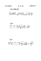
- FIG. 1 illustrates a prior art laser
- FIG. 2 illustrates the application of the teachings of the prior art to an RF waveguide laser
- FIG. 3 illustrates an embodiment of the present invention.
- FIG. 1 a laser illustrated in FIG. 1 of U.S. Pat. No. 4,176,327 is shown.
- Mirror 16 and grating 20 bound an optical cavity that includes gain cell 24 having windows 26, coupling lens 34, polarization coupler 28, quarter-wave plate 30 and electro-optic modulator 38.
- the laser may be Q-switched and cavity dumped by using modulator 38 to convert linearly polarized light to the orthogonal polarization state that is coupled out of the cavity by coupler 28.
- There is no waveguide in the laser so that the radiation is in a freespace mode, rather than in a guided mode and the problem of coupling radiation between these modes does not arise.
- the location of the cavity elements is not sensitive for this prior-art laser because there is a single cavity and no coupling problem.
- an optical system comprises two cavities, the first one bracketing waveguide 110, which is bounded by mirror 120 having a reflectivity of 100% and mirror 122 having a reflectivity of approximately 60%. Radiation passed by mirror 122 passes through Brewster coupler 124, through electro-optical modulator 126 and is reflected by grating 128, the position of which is adjusted by piezoelectric adjuster 129. Mirror 122 and grating 128 define a second optical cavity, coupled to the first optical cavity by means of mirror 122.
- FIG. 3 A laser constructed according to the present invention is illustrated in FIG. 3, in which the frequency selective device has been placed on the opposite side of the gain medium from the switching device.
- the gain cavity is now bounded by grating 128 and reflective mirror 122, with gain medium 110 being confined by end plate 121.
- the coupling cavity is now bounded by partially reflective mirror 122 and focusing mirror 132 adjusted by piezoelectric adjusting means 133 and includes coupling plate 124 and modulator 126 as before.
- Placing grating 128 close to but not in physical contact with gain medium 110 is a disadvantage, as taught by the prior art, because there is inevitably some intracavity loss introduced by the small unguided distance, even when the grating is mounted as close to the waveguide as possible.
- end plate 120 at the end of the waveguide has a reflectivity of 95% so that approximately 5% of the waveguide power is transmitted through plate 120 and reflected back by grating 128 thereby defining a third cavity, because the reflectivity of end plate 121 is less than 100%.
- Output beam 130 is now produced by having polarized light passing through mirror 122, illustratively P polarized light, passing through Brewster coupler 124 and through modulator 126 where it is converted to circularly polarized light which is reflected back by mirror 132 without scrambling the polarization, reconverted in modulator 126 to S polarized light which is outcoupled by Brewster coupler 124 with high efficiency to output beam 130.
- discharge tube 110 was 34 centimeters in length having a cross section of (2.25 mm) 2 and contained CO 2 at a pressure of 89 Torr.
- Mirror 120 had a reflectivity of approximately 95%; mirror 122 had a reflectivity of 60%; electro-optical modulator 126 was formed from a piece of CdTe, 5 centimeters in length upon which a voltage of 1,600 volts DC was impressed in order to suppress oscillation.
- Mirror 132 had a focal length of 40 centimeters and was spaced 20 centimeters from mirror 122.
- Grating 128 was used to select the 10P20 line of CO 2 and was located 14 centimeters from the end of the waveguide. This laser was operated with a pulse repetition rate of 100 kilohertz producing pulses having a 60 nanosecond FWHM.
Abstract
Description
Claims (1)
Priority Applications (6)
| Application Number | Priority Date | Filing Date | Title |
|---|---|---|---|
| US06/348,566 US4484333A (en) | 1982-02-12 | 1982-02-12 | Coupled waveguide freespace laser |
| IL67898A IL67898A0 (en) | 1982-02-12 | 1983-02-13 | Coupled waveguide freespace laser |
| PCT/US1983/000198 WO1983002857A1 (en) | 1982-02-12 | 1983-02-14 | Coupled waveguide freespace laser |
| DE8383901030T DE3380433D1 (en) | 1982-02-12 | 1983-02-14 | Coupled waveguide freespace laser |
| DE1983901030 DE100360T1 (en) | 1982-02-12 | 1983-02-14 | CLEAR SPACE LASER WITH COUPLED WAVE GUIDES. |
| EP83901030A EP0100360B1 (en) | 1982-02-12 | 1983-02-14 | Coupled waveguide freespace laser |
Applications Claiming Priority (1)
| Application Number | Priority Date | Filing Date | Title |
|---|---|---|---|
| US06/348,566 US4484333A (en) | 1982-02-12 | 1982-02-12 | Coupled waveguide freespace laser |
Publications (1)
| Publication Number | Publication Date |
|---|---|
| US4484333A true US4484333A (en) | 1984-11-20 |
Family
ID=23368569
Family Applications (1)
| Application Number | Title | Priority Date | Filing Date |
|---|---|---|---|
| US06/348,566 Expired - Fee Related US4484333A (en) | 1982-02-12 | 1982-02-12 | Coupled waveguide freespace laser |
Country Status (4)
| Country | Link |
|---|---|
| US (1) | US4484333A (en) |
| EP (1) | EP0100360B1 (en) |
| DE (1) | DE3380433D1 (en) |
| WO (1) | WO1983002857A1 (en) |
Cited By (7)
| Publication number | Priority date | Publication date | Assignee | Title |
|---|---|---|---|---|
| US4841528A (en) * | 1988-09-06 | 1989-06-20 | California Institute Of Technology | Frequency doubled, cavity dumped feedback laser |
| US4864580A (en) * | 1987-03-10 | 1989-09-05 | The United States Of America As Represented By The Secretay Of The Navy | CO2 laser pulse optimization for harmonic generation |
| US4979178A (en) * | 1989-06-20 | 1990-12-18 | The Boeing Company | Tunable narrow-linewidth semiconductor laser |
| US5022034A (en) * | 1989-06-27 | 1991-06-04 | May A D | Laser device, including control of polarization mode |
| US5206108A (en) * | 1991-12-23 | 1993-04-27 | Xerox Corporation | Method of producing a high solids replenishable liquid developer containing a friable toner resin |
| US5304451A (en) * | 1991-12-23 | 1994-04-19 | Xerox Corporation | Method of replenishing a liquid developer |
| US5306590A (en) * | 1991-12-23 | 1994-04-26 | Xerox Corporation | High solids liquid developer containing carboxyl terminated polyester toner resin |
Families Citing this family (5)
| Publication number | Priority date | Publication date | Assignee | Title |
|---|---|---|---|---|
| US4667331A (en) * | 1984-01-20 | 1987-05-19 | At&T Company And At&T Bell Laboratories | Composite cavity laser utilizing an intra-cavity electrooptic waveguide device |
| IT1181610B (en) * | 1985-03-18 | 1987-09-30 | Selenia Ind Elettroniche | OPTICAL RESONATOR FOR POWER LASER, USING A PASSIVE "Q-SWITCH" OR ANY OTHER OPTICAL ELEMENT WITH LOW DAMAGE THRESHOLD |
| US4885752A (en) * | 1988-03-28 | 1989-12-05 | Hughes Aircraft Company | Crystal modulated laser with improved resonator |
| WO2007104098A1 (en) * | 2006-03-13 | 2007-09-20 | Lighthouse Technologies Pty Ltd | Laser for generating multiple wavelengths |
| DE102012002470A1 (en) * | 2012-02-03 | 2013-08-08 | Iai Industrial Systems B.V. | CO2 laser with fast power control |
Citations (5)
| Publication number | Priority date | Publication date | Assignee | Title |
|---|---|---|---|---|
| US3387226A (en) * | 1962-07-25 | 1968-06-04 | Philips Corp | Laser comprising a block of insulating material having a channel therein filled with a gas |
| US3961283A (en) * | 1975-03-14 | 1976-06-01 | Hughes Aircraft Company | Waveguide gas laser with wavelength selective guide |
| US4174504A (en) * | 1978-01-25 | 1979-11-13 | United Technologies Corporation | Apparatus and method for cavity dumping a Q-switched laser |
| US4176327A (en) * | 1978-01-25 | 1979-11-27 | United Technologies Corporation | Method for cavity dumping a Q-switched laser |
| US4380073A (en) * | 1980-11-10 | 1983-04-12 | United Technologies Corporation | Injection control of an electro-optically Q-switched cavity-dumped laser |
-
1982
- 1982-02-12 US US06/348,566 patent/US4484333A/en not_active Expired - Fee Related
-
1983
- 1983-02-14 DE DE8383901030T patent/DE3380433D1/en not_active Expired
- 1983-02-14 WO PCT/US1983/000198 patent/WO1983002857A1/en active IP Right Grant
- 1983-02-14 EP EP83901030A patent/EP0100360B1/en not_active Expired
Patent Citations (5)
| Publication number | Priority date | Publication date | Assignee | Title |
|---|---|---|---|---|
| US3387226A (en) * | 1962-07-25 | 1968-06-04 | Philips Corp | Laser comprising a block of insulating material having a channel therein filled with a gas |
| US3961283A (en) * | 1975-03-14 | 1976-06-01 | Hughes Aircraft Company | Waveguide gas laser with wavelength selective guide |
| US4174504A (en) * | 1978-01-25 | 1979-11-13 | United Technologies Corporation | Apparatus and method for cavity dumping a Q-switched laser |
| US4176327A (en) * | 1978-01-25 | 1979-11-27 | United Technologies Corporation | Method for cavity dumping a Q-switched laser |
| US4380073A (en) * | 1980-11-10 | 1983-04-12 | United Technologies Corporation | Injection control of an electro-optically Q-switched cavity-dumped laser |
Cited By (7)
| Publication number | Priority date | Publication date | Assignee | Title |
|---|---|---|---|---|
| US4864580A (en) * | 1987-03-10 | 1989-09-05 | The United States Of America As Represented By The Secretay Of The Navy | CO2 laser pulse optimization for harmonic generation |
| US4841528A (en) * | 1988-09-06 | 1989-06-20 | California Institute Of Technology | Frequency doubled, cavity dumped feedback laser |
| US4979178A (en) * | 1989-06-20 | 1990-12-18 | The Boeing Company | Tunable narrow-linewidth semiconductor laser |
| US5022034A (en) * | 1989-06-27 | 1991-06-04 | May A D | Laser device, including control of polarization mode |
| US5206108A (en) * | 1991-12-23 | 1993-04-27 | Xerox Corporation | Method of producing a high solids replenishable liquid developer containing a friable toner resin |
| US5304451A (en) * | 1991-12-23 | 1994-04-19 | Xerox Corporation | Method of replenishing a liquid developer |
| US5306590A (en) * | 1991-12-23 | 1994-04-26 | Xerox Corporation | High solids liquid developer containing carboxyl terminated polyester toner resin |
Also Published As
| Publication number | Publication date |
|---|---|
| EP0100360A1 (en) | 1984-02-15 |
| EP0100360B1 (en) | 1989-08-16 |
| DE3380433D1 (en) | 1989-09-21 |
| WO1983002857A1 (en) | 1983-08-18 |
| EP0100360A4 (en) | 1986-01-20 |
Similar Documents
| Publication | Publication Date | Title |
|---|---|---|
| US4841528A (en) | Frequency doubled, cavity dumped feedback laser | |
| US4276518A (en) | Optical oscillator | |
| US4484333A (en) | Coupled waveguide freespace laser | |
| US5015054A (en) | Apparatus and method for increasing the bandwidth of a laser beam | |
| CN110943366B (en) | Dual-wavelength alternating Q-switching output group pulse laser and laser output method | |
| US3564450A (en) | Electro-optic q-switch using brewstek angle cut pockels cell | |
| JPH02294088A (en) | Power laser generator | |
| US4788514A (en) | Optical modulation arrangement | |
| US4546477A (en) | Pulse transmission or reflection mode laser | |
| EP0806822B1 (en) | Laser with single resonator cavity for both pump laser medium and optical parametric oscillator | |
| CN111404009B (en) | Device and method for outputting orthogonal polarization laser based on double Brewster window multiports | |
| US4512021A (en) | Passively Q-switched square bore waveguide laser | |
| US4390991A (en) | Adaptive laser output coupler | |
| US3670258A (en) | Frequency-doubled neodymium doped glass laser utilizing a lithium niobate crystal | |
| CA1166734A (en) | Unpolarised electro-optically q-switched laser | |
| GB1395093A (en) | Laser oscillator for producing band-width-limited pulses | |
| US5748664A (en) | Solid state laser with positive thermal lens | |
| CN111129917B (en) | Single-block double 45-MgO LN multi-modulation mode-based multifunctional laser device and output method | |
| CN110932069B (en) | Ultrahigh repetition frequency narrow pulse single-wavelength alternate Q-switched laser output method and laser | |
| CN110932070B (en) | Dual-wavelength alternating Q-switching narrow pulse laser and output method | |
| US6212209B1 (en) | Switchable laser using a faraday rotator | |
| US3471802A (en) | Modulated laser using a solid fabry-perot etalon having a birefringent center core | |
| CN110190501B (en) | Active Q-switching method based on volume Bragg grating | |
| CN110970793B (en) | Single longitudinal mode laser with repetition frequency 2 times electro-optical Q-switched frequency and laser output method | |
| CN116031740A (en) | RTP crystal Q-switching and Raman function composite laser and implementation mode |
Legal Events
| Date | Code | Title | Description |
|---|---|---|---|
| AS | Assignment |
Owner name: UNITED TECHNOLOGIES CORPORATION, HARTFORD, CT A CO Free format text: ASSIGNMENT OF ASSIGNORS INTEREST.;ASSIGNORS:CHENAUSKY, PETER P.;HART, RICHARD A.;LAUGHMAN, LANNY M.;AND OTHERS;REEL/FRAME:003977/0366;SIGNING DATES FROM 19820208 TO 19820209 |
|
| FPAY | Fee payment |
Year of fee payment: 4 |
|
| FPAY | Fee payment |
Year of fee payment: 8 |
|
| AS | Assignment |
Owner name: UNITED TECHNOLOGIES OPTICAL SYSTEMS, INC., FLORIDA Free format text: ASSIGNMENT OF ASSIGNORS INTEREST;ASSIGNOR:UNITED TECHNOLOGIES CORPORATION;REEL/FRAME:007249/0227 Effective date: 19941118 |
|
| AS | Assignment |
Owner name: DEMARIA ELECTROOPTICS SYSTEMS, INC., CONNECTICUT Free format text: ASSIGNMENT OF ASSIGNORS INTEREST;ASSIGNOR:UNITED TECHNOLOGIES OPTICAL SYSTEMS, INC.;REEL/FRAME:007322/0261 Effective date: 19941221 |
|
| REMI | Maintenance fee reminder mailed | ||
| LAPS | Lapse for failure to pay maintenance fees | ||
| FP | Lapsed due to failure to pay maintenance fee |
Effective date: 19961120 |
|
| STCH | Information on status: patent discontinuation |
Free format text: PATENT EXPIRED DUE TO NONPAYMENT OF MAINTENANCE FEES UNDER 37 CFR 1.362 |