US4485811A - Resection apparatus - Google Patents
Resection apparatus Download PDFInfo
- Publication number
- US4485811A US4485811A US06/372,140 US37214082A US4485811A US 4485811 A US4485811 A US 4485811A US 37214082 A US37214082 A US 37214082A US 4485811 A US4485811 A US 4485811A
- Authority
- US
- United States
- Prior art keywords
- die
- staple
- staple body
- organ
- holder
- Prior art date
- Legal status (The legal status is an assumption and is not a legal conclusion. Google has not performed a legal analysis and makes no representation as to the accuracy of the status listed.)
- Expired - Fee Related
Links
Images

Classifications
-
- A—HUMAN NECESSITIES
- A61—MEDICAL OR VETERINARY SCIENCE; HYGIENE
- A61B—DIAGNOSIS; SURGERY; IDENTIFICATION
- A61B18/00—Surgical instruments, devices or methods for transferring non-mechanical forms of energy to or from the body
- A61B18/18—Surgical instruments, devices or methods for transferring non-mechanical forms of energy to or from the body by applying electromagnetic radiation, e.g. microwaves
- A61B18/20—Surgical instruments, devices or methods for transferring non-mechanical forms of energy to or from the body by applying electromagnetic radiation, e.g. microwaves using laser
-
- A—HUMAN NECESSITIES
- A61—MEDICAL OR VETERINARY SCIENCE; HYGIENE
- A61B—DIAGNOSIS; SURGERY; IDENTIFICATION
- A61B17/00—Surgical instruments, devices or methods, e.g. tourniquets
- A61B17/068—Surgical staplers, e.g. containing multiple staples or clamps
- A61B17/072—Surgical staplers, e.g. containing multiple staples or clamps for applying a row of staples in a single action, e.g. the staples being applied simultaneously
- A61B2017/07214—Stapler heads
-
- A—HUMAN NECESSITIES
- A61—MEDICAL OR VETERINARY SCIENCE; HYGIENE
- A61B—DIAGNOSIS; SURGERY; IDENTIFICATION
- A61B18/00—Surgical instruments, devices or methods for transferring non-mechanical forms of energy to or from the body
- A61B2018/00636—Sensing and controlling the application of energy
-
- A—HUMAN NECESSITIES
- A61—MEDICAL OR VETERINARY SCIENCE; HYGIENE
- A61B—DIAGNOSIS; SURGERY; IDENTIFICATION
- A61B90/00—Instruments, implements or accessories specially adapted for surgery or diagnosis and not covered by any of the groups A61B1/00 - A61B50/00, e.g. for luxation treatment or for protecting wound edges
- A61B90/08—Accessories or related features not otherwise provided for
- A61B2090/0813—Accessories designed for easy sterilising, i.e. re-usable
Definitions
- the present invention relates generally to medicine, more specifically to surgery and has particular reference to an apparatus for resction of human organs, especially those seated in hard to access places.
- Another apparatus for staple suturing and dissecting by virtue of a laser beam as disclosed in U.S. Pat. No. 4,143,660 is known to comprise a staple body and a supporting body, each being separately applied to the organ operated upon and joined together by a special locking device, a cutting instrument, an optical waveguide for a laser beam or a mechanical knife traversable along the staple body.
- a special locking device such as a cutting instrument, an optical waveguide for a laser beam or a mechanical knife traversable along the staple body.
- Such an apparatus cannot successfully be applied for resections in hard to access places (such as the cardiac portion of the stomach, the small pelvis, thoracic cavity).
- resection of human organs with the use of the apparatus according to said patent requires extensive mobilization of the organ operated upon which involves considerable traumatization of the surrounding tissues, increased loss of blood and complicated operative techniques.
- Another apparatus for suturing the gastric walls with pi-shaped staples and resection as described in USSR Inventor's Certificate No. 209,629 comprises a cutting instrument and a suturing unit for the organ being resected which incorporates an oblong die provided with depressions for staples to bend, a staple body with a magazine and a staple ejector, said staple being mounted on its holder comprising a member arranged parallel to the die and rigidly held thereto, and another member arranged square with the first one in the plane of movement of the staple body.
- the construction features of said apparatus fail to provide an aseptic incision of the tissue operated upon, since the member arranged parallel to the die and the other member arranged square with the former one are interconnected square with each other so that the former member along with the staple body lie in the same plane, that is, in the plane of movement of the staple body, which prevents the application of a change cutting instrument, in particular a laser beam, whereby an aseptic incision cannot be produced.
- a resection apparatus comprising a cutting instrument and a suturing unit which incorporates an oblong die with a number of depressions for staples to bend, an oblong staple body with a staple magazine and a staple ejector, said staple body being detachably mounted on its holder and having a first member arranged parallel to the die and rigidly coupled thereto, and a second member arranged square with said first member in the plane of movement of the staple body and rigidly fixed to said first member, according to the present invention, the second member of the holder is offset transversely with respect to the first member so as to lie off the plane of movement of the staple body, and carries a retainer to lock the staple body in position, and provision is also made for a hold-down frame mounted on the second member traversably in the plane of movement of the staple body so as to encompass, while in one of its positions, the die along the external perimeter thereof, whereas guideways are provided on the first member for the cutting instrument to move
- An advantageous feature of the herein-proposed resection apparatus resides in that the transversely offset position of the second member of the holder with respect to the first member thereof makes it possible, after suturing the organ operated upon, to remove the staple body and replace it by any cutting instrument, in particular an optical waveguide of laser emission, in order to provide an aseptic resection in a hard to access zone of surgical intervention, while the retainer ensures high rate of such a replacement.
- the hold-down frame enables the tissue to be reliably fixed to the die after suturing which ensures against any dislodging of the sutured organ after removal of the staple body.
- a pin-point accuracy of cutting is attained which is of special importance when a laser-beam cutting instrument is resorted to.
- the guideways provided in this resection apparatus rule out any deviation of the cutting instrument.
- One of the embodiments of the present invention provides for the use of a laser-beam cutting instrument known ⁇ per se ⁇ whose optical waveguide is accommodated in a head mounted in guideways, a gap being provided between the guideways for the laser beam to pass.
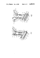
- FIG. 1 is a perspective view of a resection apparatus, according to the present invention, when assembled and put in working position of the organ being resected;
- FIG. 2 is a perspective view of a resection apparatus, according to the present invention, with the staple body removed and the optical waveguide of laser emission installed in the guideways of the first member of the staple body holder;
- FIG. 3 is a side fragmentarily cutaway view of a resection apparatus, according to the present invention.
- FIG. 4 is a front fragmentarily cutaway view of a resection apparatus, according to the present invention.
- the resection apparatus comprises the following units and components: a staple body 1, a holder 2 of the staple body 1, a die 3 with depressions 3a, a bracket 4 with a slot 5, a hold-down frame 6, an optical waveguide 7 of laser emission (not shown), whose beam serves as a cutting instrument.
- the laser is not shown for the sake of easy reading of the drawings. Moreover the laser itself is irrelevant to the essence of the present invention and there may be used as such a laser any one of the currently used lasers capable of providing adequate emissive power, e.g., the "Scharplan" laser device.
- the holder 2 comprises a first member 8 arranged parallel to the die 3 and coupled rigidly thereto, and a second member 9 rigidly interconnected with the first member 8 of the holder 2.
- the first member 8 and the die 3 are made integral with each other so that such an integral piece is yoke-shaped.
- the die 3 carries a number of the depressions 3a for bending the staples fed from the staple body 1, and has a slot 10 (FIG. 2) for the cutting instrument to pass, as well as another slot 11 to accommodate a supporting plastics insert (not shown for the sake of easy reading of the drawing) whose shape follows that of the slot 11 and involved in cutting the tissue with the knife.
- the first member 8 of the holder 2 has guideways 12 for the optical waveguide 7 to traverse, as well as an opening 13 for centre-aligning and guiding the staple body 1.
- a screw 14 (FIG. 1) which passes through a hole 15 (FIG. 2) in the die 3 situated between the rows of depressions.
- the hole 15 is closed by a plate 16 (FIGS. 3, 4) so as to prevent the laser beam from injuring the subjacent tissues and organs.
- the second member 9 of the holder 2 has a T-shaped profile, is rigidly coupled to the first member 8 of the holder 2 and is offset with respect to the first member 8 along its transverse axis for a length required in a given particular case for the laser waveguide 7 to set on the guideways 12 of the first member.
- a handle 17 is provided in the top portion of the second member 9 of the holder 2, made integral with said member.
- a slot 18 is made in the handle 17 for a rod 19 to pass, said rod entering with its end the slot 5 of the bracket 4, whereby the staple body 1 is locked in place on the second member 9 of the holder 2.
- the rod 19 is traversable along the slot 18 of the handle 17 under the action of a spring 20 which is centred about a stud 21.
- the slot 18 in the handle 17 accommodating the rod 19 and the spring 20 is closed on both sides by side members 22.
- a handhold 23 is for the rod 19 to retract into the slot 18 of the handle 17.
- the top portion of the second member 9 of the holder 2 carries the bracket 4 to fix the staple body 1 in position.
- the bracket 4 has a slot 24 to accommodate a nut 25.
- the centre of the slot 24 coincides with the centre of the opening 13 in the first member 8 and with that of the slot 10 in the die 3, whereby the staple body 1 can be centre-aligned with respect to the opening 13 in the first member 8 and the die 3.
- the second member 9 carries a link 26 of the hold-down frame 6 which is traversable in the plane of movement of the staple body 1 independently of the latter by means of the link 26. While in one of its positions (when fixing the organ being resected) the hold-down frame 6 is locked by a latch 27 actuated by a spring 28. When in this extreme position the hold-down 6 encompasses the die 3 along the external perimeter thereof so that the edge of the hold-down frame interacts with the tissue of an organ 29 to fix it on bevelled edges 30 of the die 3, at the same time stretching the tissue and forcing it against the die.
- a flange 31 is provided at the top of the link 26 of the hold-down frame 6 for conveniently moving the latter.
- a screw 32 is envisaged for the hold-down frame to lock in the topmost position.
- the staple body 1 has a tailpiece 33 and a staple head 34.
- the top portion of the tailpiece 33 of the staple body 1 has a male thread 35 which engages the nut 25 for the staple body 1 to travel with respect to the bracket 4, as well as a female thread 36 to engage a screw 37 for a staple ejector 38 to actuate.
- the staple head 34 has a T-slot 39 adapted to accommodate a change staple magazine 40 which is locked on the staple body 1 by a slider 41 actuated by a flat spring 42 made fast on the staple body 1 by screws 43.
- the staple head 34 of the staple body 1 enters the opening 13 in the first member 8 of the holder 2 and, while traversing, with its lugs 44 rests against the top surface of the first member 8, whereby a constant clearance between the magazine 40 and the die 3 is defined.
- the ejector 38 has a slot 45 to accommodate a pressure head 46 of the screw 37, and is provided in its middle portion with a hinge joint 47 necessary for disassembling and removing the ejector 38 from the staple body 1.
- a screw 48 passing through a slot 49 in the staple body 1 prevents the hinge joint 47 against spontaneous disengaging from the screw 37.
- the ejector 38 carries two rows of ejecting plates 50 to drive pi-shaped staples out of the magazine 40.
- a change knife 51 is interposed between the ejecting plates 50. Changeability of the knife makes it possible to carry out an operation by any technique without replacing the ejector 38, e.g., using the knife for dissecting the tissues, or without a knife, by applying any other cutting instrument, a laser beam in this particular case.
- the laser waveguide 7 comprises a head 52 with a T-shaped endpiece 53 made of polytetrafluoroethylene and adapted to engage the guideways 12 of the first member 8 of the holder 2, said member being arranged parallel to the die 3.
- a tube 54 is held to the head 52 by a thread (not shown), said tube being in turn held to a focussing objective 55 of the laser device through a thread (not shown).
- the apparatus assembled as shown in FIGS. 1 and 3 and a required number of the change magazines loaded with staples, are subject to sterilization by any conventional method, e.g., in an autoclave.
- the optical waveguide is sterilized separately in 96-percent ethanol.
- the operative procedure is performed as follows.
- the staple body 1 with the bracket 4 is fitted onto the holder 2 and the bracket 4 is locked by the rod 19.
- the hold-down frame 6 is fixed in its topmost position.
- the apparatus is brought behind the organ to be resected, whereupon the hold-down frame 6 is let to move down by pressing the flange 31, and the organ 29 is fixed to the die 3.
- the staple body is actuated by the nut 25 to move down till meeting the top surface of the member 8, and the latter is connected to the die 3 by the screw 14.
- the proposed resection apparatus enables one to perform an aseptic and a traumatic resection of human organs seated in hard to access places with the minimized extent of injury to the surrounding tissues and practically without bleeding.
- the application of the apparatus simplifies the operative techniques, renders any complications due to infecting the operative field less probable, cuts down the operating time, facilitates the surgeon's labour and provides better conditions for the surgical intervention as a whole.
- the apparatus is applicable not only for resection of human organs but also for formation of transplants from the stomach to establish a pediculate gastroma.
Abstract
Description
Claims (4)
Applications Claiming Priority (5)
| Application Number | Priority Date | Filing Date | Title |
|---|---|---|---|
| SU802881888A SU1042742A1 (en) | 1980-02-08 | 1980-02-08 | Surgical suturing apparatus for application of linear suture |
| SU2881888 | 1980-02-08 | ||
| GB08212511A GB2119694B (en) | 1980-02-08 | 1982-04-29 | Resection apparatus |
| FR8208085A FR2526302A1 (en) | 1980-02-08 | 1982-05-10 | SURGICAL APPARATUS FOR ORGAN RESECTION |
| DE3220013A DE3220013C2 (en) | 1980-02-08 | 1982-05-27 | Resection device |
Publications (1)
| Publication Number | Publication Date |
|---|---|
| US4485811A true US4485811A (en) | 1984-12-04 |
Family
ID=27432817
Family Applications (1)
| Application Number | Title | Priority Date | Filing Date |
|---|---|---|---|
| US06/372,140 Expired - Fee Related US4485811A (en) | 1980-02-08 | 1982-04-27 | Resection apparatus |
Country Status (4)
| Country | Link |
|---|---|
| US (1) | US4485811A (en) |
| DE (1) | DE3220013C2 (en) |
| FR (1) | FR2526302A1 (en) |
| GB (1) | GB2119694B (en) |
Cited By (37)
| Publication number | Priority date | Publication date | Assignee | Title |
|---|---|---|---|---|
| US4665916A (en) * | 1985-08-09 | 1987-05-19 | United States Surgical Corporation | Surgical stapler apparatus |
| EP0323016A1 (en) * | 1987-12-31 | 1989-07-05 | United States Surgical Corporation | Surgical fastener cartridge |
| US5180092A (en) * | 1992-02-05 | 1993-01-19 | Lawrence Crainich | Linear surgical stapling instrument |
| US5190203A (en) * | 1990-10-05 | 1993-03-02 | United States Surgical Corporation | Controlled closure mechanism |
| US5641111A (en) * | 1995-06-28 | 1997-06-24 | Ethicon Endo-Surgery, Inc. | Surgical stapling instrument with anvil cutting guide |
| US7032799B2 (en) | 2001-10-05 | 2006-04-25 | Tyco Healthcare Group Lp | Surgical stapling apparatus and method |
| US20060144898A1 (en) * | 2001-03-29 | 2006-07-06 | Federico Bilotti | Surgical stapling instrument |
| US20060241660A1 (en) * | 1999-07-28 | 2006-10-26 | Cardica, Inc. | Anastomosis system with flexible shaft |
| US7238195B2 (en) | 2002-05-10 | 2007-07-03 | Tyco Healthcare Group Lp | Wound closure material applicator and stapler |
| US20070233163A1 (en) * | 1999-07-28 | 2007-10-04 | Cardica, Inc. | Anastomosis System with Cutting Element |
| US20070246507A1 (en) * | 2000-11-20 | 2007-10-25 | Medigus Ltd. | Stapler for endoscopes |
| US7296722B2 (en) | 2003-10-17 | 2007-11-20 | Tyco Healthcare Group Lp | Surgical fastener applying apparatus with controlled beam deflection |
| US7334717B2 (en) | 2001-10-05 | 2008-02-26 | Tyco Healthcare Group Lp | Surgical fastener applying apparatus |
| US7407076B2 (en) | 2000-10-13 | 2008-08-05 | Tyco Healthcare Group Lp | Surgical stapling device |
| US20100276470A1 (en) * | 2005-07-27 | 2010-11-04 | Power Medical Interventions, Llc | Surgical device |
| EP2266471A3 (en) * | 2002-01-08 | 2011-04-06 | Tyco Healthcare Group LP | A surgical device |
| US7963432B2 (en) | 2007-09-06 | 2011-06-21 | Cardica, Inc. | Driverless surgical stapler |
| US8021373B2 (en) | 2001-11-30 | 2011-09-20 | Tyco Healthcare Group Lp | Surgical device |
| US8056791B2 (en) | 1999-07-12 | 2011-11-15 | Tyco Healthcare Group Lp | Expanding parallel jaw device for use with an electromechanical driver device |
| US8328064B2 (en) | 2009-05-06 | 2012-12-11 | Covidien Lp | Pin locking mechanism for a surgical instrument |
| US8353436B2 (en) | 2009-05-06 | 2013-01-15 | Covidien Lp | Pin locking mechanism for a surgical instrument |
| US8827137B2 (en) | 2010-03-25 | 2014-09-09 | Covidien Lp | Pin alignment assembly for surgical stapler |
| US8900232B2 (en) | 2011-05-06 | 2014-12-02 | Covidien Lp | Bifurcated shaft for surgical instrument |
| US9113878B2 (en) | 2002-01-08 | 2015-08-25 | Covidien Lp | Pinion clip for right angle linear cutter |
| US9168039B1 (en) | 2007-09-06 | 2015-10-27 | Cardica, Inc. | Surgical stapler with staples of different sizes |
| US9345478B2 (en) | 2007-09-06 | 2016-05-24 | Cardica, Inc. | Method for surgical stapling |
| US9775611B2 (en) | 2015-01-06 | 2017-10-03 | Covidien Lp | Clam shell surgical stapling loading unit |
| US9855040B2 (en) | 2015-03-04 | 2018-01-02 | Covidien Lp | Surgical stapling loading unit having articulating jaws |
| USD814632S1 (en) | 2016-10-21 | 2018-04-03 | Covidien Lp | Staple cartridge |
| US10702269B2 (en) | 2014-12-25 | 2020-07-07 | Covidien Lp | Surgical stapling devices |
| US10939910B2 (en) | 2016-12-02 | 2021-03-09 | Covidien Lp | Surgical stapling instrument with curved end effector |
| US10945730B2 (en) | 2018-06-25 | 2021-03-16 | Covidien Lp | Stapling device with selectively advanceable alignment pin |
| US10993714B2 (en) | 2017-11-28 | 2021-05-04 | Covidien Lp | Surgical stapling instrument and associated trigger mechanisms |
| US11744584B2 (en) | 2020-06-09 | 2023-09-05 | Covidien Lp | Alignment pin assembly for surgical stapler |
| US11806012B2 (en) | 2019-11-01 | 2023-11-07 | Covidien Lp | Surgical stapling device with knife blade lock |
| US11826044B2 (en) | 2019-08-02 | 2023-11-28 | Covidien Lp | Surgical stapling device with curved tool assembly |
| US11857185B2 (en) | 2019-12-18 | 2024-01-02 | Covidien Lp | Surgical stapling device with shipping cap |
Families Citing this family (4)
| Publication number | Priority date | Publication date | Assignee | Title |
|---|---|---|---|---|
| US4617928A (en) * | 1984-09-17 | 1986-10-21 | Alfranca Jose Maria P | Surgical instrument for practicing mechanical sutures and biopsies |
| CH667986A5 (en) * | 1984-10-16 | 1988-11-30 | Oleg Xenofontovich D Skobelkin | SETTING DEVICE FOR WIND CLASPS. |
| WO1986005676A1 (en) * | 1985-03-29 | 1986-10-09 | Politzer Eugene Jim | Method and apparatus for shaving the beard |
| FR2579446B1 (en) * | 1985-03-29 | 1989-08-04 | Politzer Eugene | METHOD FOR REMOVING HAIR, DOWN AND BARBES BY A BLADE-FREE METHOD |
Citations (6)
| Publication number | Priority date | Publication date | Assignee | Title |
|---|---|---|---|---|
| SU209629A1 (en) * | О. К. Скобелкин , А. И. Иванов | APPARATUS FOR STAINING THE WALLS OF THE STOMACH BY P-METAL METAL BRIDGES | ||
| GB1276239A (en) * | 1970-10-14 | 1972-06-01 | Vnii Khirurgicheskoi Apparatur | Surgical device for suturing tissue with staples |
| SU511939A1 (en) * | 1973-07-13 | 1976-04-30 | Центральная Научно-Исследовательская Лаборатория При 4-М Главном Управлении | Apparatus for imposing arcuate suture on the greater curvature of the stomach |
| SU625696A1 (en) * | 1974-06-03 | 1978-09-30 | Предприятие П/Я Г-4147 | Apparatus for obtaining tube from greater curvature of the stomach |
| US4143660A (en) * | 1977-05-09 | 1979-03-13 | Malyshev Boris N | Method of surgery making use of laser emission and an apparatus for accomplishing same |
| SU584439A1 (en) * | 1976-03-09 | 1979-07-30 | Предприятие П/Я Г-4147 | Tissue-dissecting device |
Family Cites Families (3)
| Publication number | Priority date | Publication date | Assignee | Title |
|---|---|---|---|---|
| SU143738A1 (en) * | 1960-06-15 | 1960-11-30 | А.А. Стрекопытов | Method of suturing lung tissue by double-sided immersion sutures |
| SU566574A1 (en) * | 1975-05-04 | 1977-07-30 | Всесоюзный научно-исследовательский и испытательный институт медицинской техники | Apparatus for applying linear agraffe suture on organs and tissue |
| SU942719A1 (en) * | 1979-11-23 | 1982-07-15 | Всесоюзный научно-исследовательский и испытательный институт медицинской техники | Surgical suturing apparatus for application of linear sutures |
-
1982
- 1982-04-27 US US06/372,140 patent/US4485811A/en not_active Expired - Fee Related
- 1982-04-29 GB GB08212511A patent/GB2119694B/en not_active Expired
- 1982-05-10 FR FR8208085A patent/FR2526302A1/en active Granted
- 1982-05-27 DE DE3220013A patent/DE3220013C2/en not_active Expired
Patent Citations (7)
| Publication number | Priority date | Publication date | Assignee | Title |
|---|---|---|---|---|
| SU209629A1 (en) * | О. К. Скобелкин , А. И. Иванов | APPARATUS FOR STAINING THE WALLS OF THE STOMACH BY P-METAL METAL BRIDGES | ||
| SU189517A1 (en) * | ||||
| GB1276239A (en) * | 1970-10-14 | 1972-06-01 | Vnii Khirurgicheskoi Apparatur | Surgical device for suturing tissue with staples |
| SU511939A1 (en) * | 1973-07-13 | 1976-04-30 | Центральная Научно-Исследовательская Лаборатория При 4-М Главном Управлении | Apparatus for imposing arcuate suture on the greater curvature of the stomach |
| SU625696A1 (en) * | 1974-06-03 | 1978-09-30 | Предприятие П/Я Г-4147 | Apparatus for obtaining tube from greater curvature of the stomach |
| SU584439A1 (en) * | 1976-03-09 | 1979-07-30 | Предприятие П/Я Г-4147 | Tissue-dissecting device |
| US4143660A (en) * | 1977-05-09 | 1979-03-13 | Malyshev Boris N | Method of surgery making use of laser emission and an apparatus for accomplishing same |
Cited By (99)
| Publication number | Priority date | Publication date | Assignee | Title |
|---|---|---|---|---|
| US4665916A (en) * | 1985-08-09 | 1987-05-19 | United States Surgical Corporation | Surgical stapler apparatus |
| EP0323016A1 (en) * | 1987-12-31 | 1989-07-05 | United States Surgical Corporation | Surgical fastener cartridge |
| US5190203A (en) * | 1990-10-05 | 1993-03-02 | United States Surgical Corporation | Controlled closure mechanism |
| US5180092A (en) * | 1992-02-05 | 1993-01-19 | Lawrence Crainich | Linear surgical stapling instrument |
| US5641111A (en) * | 1995-06-28 | 1997-06-24 | Ethicon Endo-Surgery, Inc. | Surgical stapling instrument with anvil cutting guide |
| US9078654B2 (en) | 1999-06-02 | 2015-07-14 | Covidien Lp | Surgical device |
| US8186559B1 (en) | 1999-07-12 | 2012-05-29 | Tyco Healthcare Group Lp | Expanding parallel jaw device for use with an electromechanical driver device |
| US8459523B2 (en) | 1999-07-12 | 2013-06-11 | Covidien Lp | Expanding parallel jaw device for use with an electromechanical driver device |
| US8056791B2 (en) | 1999-07-12 | 2011-11-15 | Tyco Healthcare Group Lp | Expanding parallel jaw device for use with an electromechanical driver device |
| US8118208B2 (en) | 1999-07-12 | 2012-02-21 | Tyco Healthcare Group Lp | Expanding parallel jaw device for use with an electromechanical driver device |
| US9622748B2 (en) | 1999-07-28 | 2017-04-18 | Dextera Surgical Inc. | Anastomosis system with flexible shaft |
| US20070233163A1 (en) * | 1999-07-28 | 2007-10-04 | Cardica, Inc. | Anastomosis System with Cutting Element |
| US20060241660A1 (en) * | 1999-07-28 | 2006-10-26 | Cardica, Inc. | Anastomosis system with flexible shaft |
| US9186139B2 (en) | 2000-02-22 | 2015-11-17 | Covidien Lp | Surgical device |
| US8091754B2 (en) | 2000-10-13 | 2012-01-10 | Tyco Healthcare Group Lp | Surgical fastener applying apparatus |
| US10959729B2 (en) | 2000-10-13 | 2021-03-30 | Covidien Lp | Surgical fastener applying apparatus |
| US8505801B2 (en) | 2000-10-13 | 2013-08-13 | Covidien Lp | Surgical fastener applying apparatus |
| US7407076B2 (en) | 2000-10-13 | 2008-08-05 | Tyco Healthcare Group Lp | Surgical stapling device |
| US10231733B2 (en) | 2000-10-13 | 2019-03-19 | Covidien Lp | Surgical fastener applying apparatus |
| US9402629B2 (en) | 2000-10-13 | 2016-08-02 | Covidien Lp | Surgical fastener applying apparatus |
| US8074861B2 (en) | 2000-10-13 | 2011-12-13 | Tyco Healthcare Group Lp | Surgical fastener applying apparatus |
| US8807415B2 (en) | 2000-11-20 | 2014-08-19 | Medigus Ltd. | Stapler for endoscopes |
| US8328827B2 (en) | 2000-11-20 | 2012-12-11 | Medigus Ltd. | Stapler for endoscopes |
| US20090272785A1 (en) * | 2000-11-20 | 2009-11-05 | Medigus Ltd. | Stapler for endoscopes |
| US8257373B2 (en) | 2000-11-20 | 2012-09-04 | Medigus Ltd. | Device for performing a fundoplication surgical procedure |
| US20070276436A1 (en) * | 2000-11-20 | 2007-11-29 | Medigus Ltd. | Stapler for endoscopes |
| US20070251976A1 (en) * | 2000-11-20 | 2007-11-01 | Medigus Ltd. | Stapler for endoscopes |
| US20070251975A1 (en) * | 2000-11-20 | 2007-11-01 | Medigus Ltd. | Stapler for endoscopes |
| US8006886B2 (en) * | 2000-11-20 | 2011-08-30 | Medigus Ltd. | Stapler for endoscopes |
| US20070246507A1 (en) * | 2000-11-20 | 2007-10-25 | Medigus Ltd. | Stapler for endoscopes |
| US8646673B2 (en) | 2001-03-29 | 2014-02-11 | Ethicon Endo-Surgery, Inc. | Surgical stapling instrument |
| US20100308101A1 (en) * | 2001-03-29 | 2010-12-09 | Federico Bilotti | Surgical Stapling Instrument |
| US20060144898A1 (en) * | 2001-03-29 | 2006-07-06 | Federico Bilotti | Surgical stapling instrument |
| US7326232B2 (en) | 2001-10-05 | 2008-02-05 | Tyco Healthcare Group Lp | Surgical stapling apparatus and method |
| US7631794B2 (en) | 2001-10-05 | 2009-12-15 | Tyco Healthcare Group Lp | Surgical fastener applying apparatus |
| US7032799B2 (en) | 2001-10-05 | 2006-04-25 | Tyco Healthcare Group Lp | Surgical stapling apparatus and method |
| US7942300B2 (en) | 2001-10-05 | 2011-05-17 | Tyco Healthcare Group Lp | Surgical fastener applying apparatus |
| US7334717B2 (en) | 2001-10-05 | 2008-02-26 | Tyco Healthcare Group Lp | Surgical fastener applying apparatus |
| US7631793B2 (en) | 2001-10-05 | 2009-12-15 | Tyco Healthcare Group Lp | Surgical fastener applying apparatus |
| US8740932B2 (en) | 2001-11-30 | 2014-06-03 | Covidien Lp | Surgical device |
| US8021373B2 (en) | 2001-11-30 | 2011-09-20 | Tyco Healthcare Group Lp | Surgical device |
| US8512359B2 (en) | 2001-11-30 | 2013-08-20 | Covidien Lp | Surgical device |
| US8518074B2 (en) | 2002-01-08 | 2013-08-27 | Covidien Lp | Surgical device |
| EP2266471A3 (en) * | 2002-01-08 | 2011-04-06 | Tyco Healthcare Group LP | A surgical device |
| US8016855B2 (en) | 2002-01-08 | 2011-09-13 | Tyco Healthcare Group Lp | Surgical device |
| US9113878B2 (en) | 2002-01-08 | 2015-08-25 | Covidien Lp | Pinion clip for right angle linear cutter |
| US8858589B2 (en) | 2002-01-08 | 2014-10-14 | Covidien Lp | Surgical device |
| US7571845B2 (en) | 2002-05-10 | 2009-08-11 | Tyco Healthcare Group Lp | Surgical stapling apparatus having a wound closure material applicator assembly |
| US7740160B2 (en) | 2002-05-10 | 2010-06-22 | Tyco Healthcare Group Lp | Surgical stapling apparatus having a wound closure material applicator assembly |
| US8286850B2 (en) | 2002-05-10 | 2012-10-16 | Tyco Healthcare Group Lp | Surgical stapling apparatus having a wound closure material applicator assembly |
| US7238195B2 (en) | 2002-05-10 | 2007-07-03 | Tyco Healthcare Group Lp | Wound closure material applicator and stapler |
| US9241711B2 (en) | 2003-10-17 | 2016-01-26 | Covidien Lp | Surgical fastener applying apparatus with controlled beam deflection |
| US7543729B2 (en) | 2003-10-17 | 2009-06-09 | Tyco Healthcare Group Lp | Surgical fastener applying apparatus with controlled beam deflection |
| US8292149B2 (en) | 2003-10-17 | 2012-10-23 | Tyco Healthcare Group Lp | Surgical fastener applying apparatus with controlled beam deflection |
| US10835252B2 (en) | 2003-10-17 | 2020-11-17 | Covidien Lp | Surgical fastener applying apparatus with controlled beam deflection |
| US10154843B2 (en) | 2003-10-17 | 2018-12-18 | Covidien Lp | Surgical fastener applying apparatus with controlled beam deflection |
| US7296722B2 (en) | 2003-10-17 | 2007-11-20 | Tyco Healthcare Group Lp | Surgical fastener applying apparatus with controlled beam deflection |
| US8701961B2 (en) | 2003-10-17 | 2014-04-22 | Covidien Lp | Surgical fastener applying apparatus with controlled beam deflection |
| US8011552B2 (en) | 2003-10-17 | 2011-09-06 | Tyco Healthcare Group Lp | Surgical fastener applying apparatus with controlled beam deflection |
| US7699205B2 (en) | 2003-10-17 | 2010-04-20 | Tyco Healthcare Group Lp | Surgical fastener applying apparatus with controlled beam deflection |
| US8381828B2 (en) | 2005-07-27 | 2013-02-26 | Covidien Lp | Surgical device |
| US8132704B2 (en) | 2005-07-27 | 2012-03-13 | Tyco Healthcare Group Lp | Surgical device |
| US20100276470A1 (en) * | 2005-07-27 | 2010-11-04 | Power Medical Interventions, Llc | Surgical device |
| US8851353B2 (en) | 2005-07-27 | 2014-10-07 | Covidien Lp | Surgical device |
| US7963432B2 (en) | 2007-09-06 | 2011-06-21 | Cardica, Inc. | Driverless surgical stapler |
| US9655618B2 (en) | 2007-09-06 | 2017-05-23 | Dextera Surgical Inc. | Surgical method utilizing a true multiple-fire surgical stapler |
| US9144427B2 (en) | 2007-09-06 | 2015-09-29 | Cardica, Inc. | Surgical method utilizing a true multiple-fire surgical stapler |
| US10405856B2 (en) | 2007-09-06 | 2019-09-10 | Aesculap Ag | Method for surgical stapling |
| US8679155B2 (en) | 2007-09-06 | 2014-03-25 | Cardica, Inc. | Surgical method utilizing a true multiple-fire surgical stapler |
| US8789738B2 (en) | 2007-09-06 | 2014-07-29 | Cardica, Inc. | Surgical method for stapling tissue |
| US8439245B2 (en) | 2007-09-06 | 2013-05-14 | Cardica, Inc. | True multi-fire endocutter |
| US8272551B2 (en) | 2007-09-06 | 2012-09-25 | Cardica, Inc. | Method of utilizing a driverless surgical stapler |
| US9345478B2 (en) | 2007-09-06 | 2016-05-24 | Cardica, Inc. | Method for surgical stapling |
| US9168039B1 (en) | 2007-09-06 | 2015-10-27 | Cardica, Inc. | Surgical stapler with staples of different sizes |
| US8353436B2 (en) | 2009-05-06 | 2013-01-15 | Covidien Lp | Pin locking mechanism for a surgical instrument |
| US9675356B2 (en) | 2009-05-06 | 2017-06-13 | Covidien Lp | Pin locking mechanism for a surgical instrument |
| US9833237B2 (en) | 2009-05-06 | 2017-12-05 | Covidien Lp | Pin locking mechanism for a surgical instrument |
| US9113869B2 (en) | 2009-05-06 | 2015-08-25 | Covidien Lp | Pin locking mechanism for a surgical instrument |
| US9198658B2 (en) | 2009-05-06 | 2015-12-01 | Covidien Lp | Pin locking mechanism for a surgical instrument |
| US9314264B2 (en) | 2009-05-06 | 2016-04-19 | Covidien Lp | Pin locking mechanism for a surgical instrument |
| US8328064B2 (en) | 2009-05-06 | 2012-12-11 | Covidien Lp | Pin locking mechanism for a surgical instrument |
| US8827137B2 (en) | 2010-03-25 | 2014-09-09 | Covidien Lp | Pin alignment assembly for surgical stapler |
| US9668808B2 (en) | 2011-05-06 | 2017-06-06 | Covidien Lp | Bifurcated shaft for surgical instrument |
| US8900232B2 (en) | 2011-05-06 | 2014-12-02 | Covidien Lp | Bifurcated shaft for surgical instrument |
| US10702269B2 (en) | 2014-12-25 | 2020-07-07 | Covidien Lp | Surgical stapling devices |
| US9775611B2 (en) | 2015-01-06 | 2017-10-03 | Covidien Lp | Clam shell surgical stapling loading unit |
| US10806447B2 (en) * | 2015-03-04 | 2020-10-20 | Covidien Lp | Surgical stapling loading unit having articulating jaws |
| US20180116657A1 (en) * | 2015-03-04 | 2018-05-03 | Covidien Lp | Surgical stapling loading unit having articulating jaws |
| US9855040B2 (en) | 2015-03-04 | 2018-01-02 | Covidien Lp | Surgical stapling loading unit having articulating jaws |
| USD814632S1 (en) | 2016-10-21 | 2018-04-03 | Covidien Lp | Staple cartridge |
| US10939910B2 (en) | 2016-12-02 | 2021-03-09 | Covidien Lp | Surgical stapling instrument with curved end effector |
| US11666329B2 (en) | 2016-12-02 | 2023-06-06 | Covidien Lp | Surgical stapling instrument with curved end effector |
| US10993714B2 (en) | 2017-11-28 | 2021-05-04 | Covidien Lp | Surgical stapling instrument and associated trigger mechanisms |
| US11617578B2 (en) | 2017-11-28 | 2023-04-04 | Covidien Lp | Surgical stapling instrument and associated trigger mechanisms |
| US10945730B2 (en) | 2018-06-25 | 2021-03-16 | Covidien Lp | Stapling device with selectively advanceable alignment pin |
| US11826044B2 (en) | 2019-08-02 | 2023-11-28 | Covidien Lp | Surgical stapling device with curved tool assembly |
| US11806012B2 (en) | 2019-11-01 | 2023-11-07 | Covidien Lp | Surgical stapling device with knife blade lock |
| US11857185B2 (en) | 2019-12-18 | 2024-01-02 | Covidien Lp | Surgical stapling device with shipping cap |
| US11744584B2 (en) | 2020-06-09 | 2023-09-05 | Covidien Lp | Alignment pin assembly for surgical stapler |
Also Published As
| Publication number | Publication date |
|---|---|
| GB2119694A (en) | 1983-11-23 |
| GB2119694B (en) | 1985-08-29 |
| FR2526302B1 (en) | 1984-11-09 |
| DE3220013C2 (en) | 1985-01-10 |
| FR2526302A1 (en) | 1983-11-10 |
| DE3220013A1 (en) | 1983-12-08 |
Similar Documents
| Publication | Publication Date | Title |
|---|---|---|
| US4485811A (en) | Resection apparatus | |
| US11123071B2 (en) | Staple cartridge for us with a surgical instrument | |
| US11317918B2 (en) | Loading unit for surgical instruments with low profile pushers | |
| US3949923A (en) | Surgical suturing instrument | |
| US4629107A (en) | Ligating instrument | |
| CA1261226A (en) | Surgical stapling instrument with jaw latching mechanism and disposable staple cartridge | |
| US4788978A (en) | Surgical instrument for applying linear staple sutures and intersecting the tissue therebetween | |
| US20070233163A1 (en) | Anastomosis System with Cutting Element | |
| US20140252061A1 (en) | Pivoting Screw for Use with a Pair of Jaw Members of a Surgical Instrument | |
| US20100213241A1 (en) | Staple cartridge | |
| GB2145025A (en) | Ligating instrument | |
| JPH0342100B2 (en) | ||
| US20220167985A1 (en) | Tool assemblies with a gap locking member | |
| US20220330941A1 (en) | Features to enhance staple height consistency in curved surgical stapler | |
| US11944306B2 (en) | Surgical stapler including a replaceable staple cartridge | |
| JPS58200739A (en) | Incision apparatus | |
| CN216652369U (en) | Suturing device | |
| US20230255627A1 (en) | Curved surgical stapling device | |
| US11439392B2 (en) | Surgical stapling device and fastener for pathological exam | |
| WO2022056774A1 (en) | Surgical fastener applying apparatus with lockout assembly | |
| SU1560138A1 (en) | Apparatus for suturing organs and vessels |
Legal Events
| Date | Code | Title | Description |
|---|---|---|---|
| AS | Assignment |
Owner name: VSESOJUZNY NAUCHNY TSENTR KHIRURGII USSR, MOSCOW, Free format text: ASSIGNMENT OF ASSIGNORS INTEREST.;ASSIGNORS:CHERNOUSOV, ALEXANDR F.;DOMRACHEV, SERGEI A.;IVANOV, ALEXEI I.;AND OTHERS;REEL/FRAME:004301/0399 Effective date: 19840724 |
|
| FEPP | Fee payment procedure |
Free format text: PAYOR NUMBER ASSIGNED (ORIGINAL EVENT CODE: ASPN); ENTITY STATUS OF PATENT OWNER: LARGE ENTITY |
|
| FPAY | Fee payment |
Year of fee payment: 4 |
|
| FEPP | Fee payment procedure |
Free format text: PAYER NUMBER DE-ASSIGNED (ORIGINAL EVENT CODE: RMPN); ENTITY STATUS OF PATENT OWNER: LARGE ENTITY Free format text: PAYOR NUMBER ASSIGNED (ORIGINAL EVENT CODE: ASPN); ENTITY STATUS OF PATENT OWNER: LARGE ENTITY |
|
| REMI | Maintenance fee reminder mailed | ||
| LAPS | Lapse for failure to pay maintenance fees | ||
| FP | Lapsed due to failure to pay maintenance fee |
Effective date: 19921208 |
|
| STCH | Information on status: patent discontinuation |
Free format text: PATENT EXPIRED DUE TO NONPAYMENT OF MAINTENANCE FEES UNDER 37 CFR 1.362 |