US4514743A - Ink jet filtered-chamber print head - Google Patents
Ink jet filtered-chamber print head Download PDFInfo
- Publication number
- US4514743A US4514743A US06/598,509 US59850984A US4514743A US 4514743 A US4514743 A US 4514743A US 59850984 A US59850984 A US 59850984A US 4514743 A US4514743 A US 4514743A
- Authority
- US
- United States
- Prior art keywords
- ink
- print head
- ducts
- enlargements
- filter material
- Prior art date
- Legal status (The legal status is an assumption and is not a legal conclusion. Google has not performed a legal analysis and makes no representation as to the accuracy of the status listed.)
- Expired - Fee Related
Links
- 238000007639 printing Methods 0.000 claims abstract description 5
- 239000011159 matrix material Substances 0.000 claims abstract description 3
- 239000000463 material Substances 0.000 claims description 14
- 239000012530 fluid Substances 0.000 claims description 2
- 230000001960 triggered effect Effects 0.000 description 3
- 238000010276 construction Methods 0.000 description 2
- 230000008602 contraction Effects 0.000 description 2
- 230000009931 harmful effect Effects 0.000 description 2
- 238000013016 damping Methods 0.000 description 1
- 230000006735 deficit Effects 0.000 description 1
- 230000000694 effects Effects 0.000 description 1
- 230000002349 favourable effect Effects 0.000 description 1
- 238000000034 method Methods 0.000 description 1
- 238000006386 neutralization reaction Methods 0.000 description 1
- 230000003472 neutralizing effect Effects 0.000 description 1
- 230000000644 propagated effect Effects 0.000 description 1
- 238000007789 sealing Methods 0.000 description 1
- 230000007704 transition Effects 0.000 description 1
Images
Classifications
-
- B—PERFORMING OPERATIONS; TRANSPORTING
- B41—PRINTING; LINING MACHINES; TYPEWRITERS; STAMPS
- B41J—TYPEWRITERS; SELECTIVE PRINTING MECHANISMS, i.e. MECHANISMS PRINTING OTHERWISE THAN FROM A FORME; CORRECTION OF TYPOGRAPHICAL ERRORS
- B41J2/00—Typewriters or selective printing mechanisms characterised by the printing or marking process for which they are designed
- B41J2/005—Typewriters or selective printing mechanisms characterised by the printing or marking process for which they are designed characterised by bringing liquid or particles selectively into contact with a printing material
- B41J2/01—Ink jet
- B41J2/17—Ink jet characterised by ink handling
- B41J2/175—Ink supply systems ; Circuit parts therefor
- B41J2/17563—Ink filters
Definitions
- the invention relates to a piezoelectrically driven print head for dot matrix ink printers with a plurality of print jets in the form of ink ducts receiving the printing fluid, which ducts are respectively enclosed by a piezoelectric drive element and are connected by way of a filter arrangement with an ink chamber common to them, wherein the ink ducts have a substantially greater length than the drive elements.
- a print head of this type is known from German Pat. No. 2,543,451. Its ink ducts empty by their jet openings on the point of the print head in a grid-like distribution, by which it becomes possible, with a suitable selective triggering the piezoelectric drive element with electrical voltage pulses during a line-by-line movement of the print head, to record characters on a recording support.
- the piezoelectric drive elements in the form of little tubes as a result of their being triggered with the voltage pulses, cause a corresponding pulse-like contraction of the ink ducts, by means of which pressure pulses are exerted on the ink present in the ink ducts, which in turn leads to the detaching of ink droplets at the jet openings of the ink ducts as well as to their being transferred to the recording support.
- the distance between the jet openings and the recording support cannot be increased at will and for the purpose of generating the most accurate possible mosaic characters can be only 0.5 to 1 mm at most.
- An example of such an application case is the marking of bank deposit books in banking practice within the scope of an automatic accounting process.
- the page to be marked depending on its position in the deposit book or on the number of marking operations already done, may be at a long distance or short distance from its print head or its jet opening. Within a distance range which may be 3 mm or more, however, an always constant printing accuracy must be ensured.
- the pressure pulses causing this must be generated with a higher intensity in order to ensure a droplet flow in a straight line.
- the amplitude of the control voltage pulses applied to the piezoelectric drive elements can be increased, but relatively low limits are imposed on such an increase, which are probably due to the mechanical behavior of the drive element itself and do not lead to the desired result but rather have the effect of greater printing inaccuracies.
- the problem of the invention therefore consists in supplying a construction for a print head of the type mentioned at the start which will make it possible to generate recordings with satisfactory accuracy over greater distances than previously without the necessity of making allowance for impairment of the print accuracy due to increased control voltage amplitudes.
- a choke plate and a close-mesh grid are provided as the filter arrangement between the ink ducts and the ink chamber common to them, which arrangement is to prevent air from going through the ink ducts into the ink chamber.
- the choke plate contains a very narrow passage opening for each ink duct, which openings are to dissipate peak pressures in the ink supply system and ensure a mutual neutralizing of the pressure actions of the ink ducts with one another.
- a filter arrangement in the form of a layer of a capillary filter material is provided between the ink ducts and the ink chamber.
- each ink duct has a funnel-shaped enlargement bordering on this layer. It has been found that with this arrangement a considerably better utilization of the energy of the pressure pulses generated by the piezoelectric drive elements is possible, which causes the ink droplets emerging at the jet openings to be able to fly across a considerably greater distance to the recording support while maintaining their predetermined path.
- the filter material shows a mesh spacing of about 0.035 mm and a thickness of about 0.05 mm. This dimensioning seems to ensure a particularly good capillary action of the filter material for the continuous supplying of the individual ink ducts with ink, combined with an adequate filter action.
- Recesses shaped in very different ways in the part containing the ink ducts may be provided as the funnel-shaped enlargements of the ink ducts.
- an embodiment has proven particularly advantageous in which enlargements of the ink ducts are built in conical shape with an opening angle of about 60'.
- This construction in turn gives an advantageous dimensioning of the enlargements when these show a diameter of about 3 mm where they go into the filter material.
- This dimension then has quite a favorable ratio of the diameter of the ink ducts, which is ordinarily of the order of 0.5 to 0.7 mm at the point of opening into the filter layer.
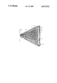
- the single FIGURE illustrates an embodiment of the invention.
- a print head according to the invention is diagrammatically represented in a cross section as an embodiment example.
- This print head consists essentially of a plastic part 10 which is constructed in conical shape and into which the ink ducts 11 are inserted which converge at the left tip of the part 10 and there empty with jet openings 12.
- a recording support 13 At a distance from the tip of the part 10 is arranged a recording support 13 on which the ink droplets emerging from the jet openings 12 can record characters due to the mosaic-like distribution of the jet openings 12 when there is a relative motion between the part 10 and the recording support 13.
- the ink droplets are produced by having tubular piezoelectric drive elements 14 which surround the ink ducts 11 selectively triggered in a rapid sequence with voltage pulses, in which way they become deformed in the manner of a contraction and generate a pressure pulse in the respective ink duct 11 which pulse acts on the ink present in the ink duct 11 in such a way that the ink becomes detached in droplet form at the jet openings 12 and is shot onto the recording support 13.
- An ink supply system for supplying the ink ducts 11 with ink, the reservoir of which system is not represented in the FIGURE.
- the ink is fed from such a reservoir at 15 into the print head and goes into an ink chamber 16 common to all the ink ducts, which chamber is formed between the part 10 and a rear end plate 17 which is joined to the part 10 in a sealing manner and is for example screwed onto it (not represented).
- the common ink chamber 16 is so narrow that the ink fed in at 15 rises up in it by capillary action and fills it full.
- the width of the ink chamber may for example be 0.1 to 0.3 mm.
- the ink chamber 16 is bounded on its left side by a layer 18 of a filter material which for example may consist of a fibrous plastic material with a mesh spacing of 0.035 mm.
- the thickness of this layer 18 may be about 0.05 to 0.3 mm.
- the individual ink ducts 11 are more than twice as long as the drive elements 14 and are connected with the layer 18 of the filter material by way of one funnel-shaped enlargement 19 each, which in the embodiment example represented is constructed in cone shape.
- the opening angle of this funnel shape may be 60' for example.
- the ink ducts 11 may for example be 35 mm long while the drive elements 14 are then about 12 mm long.
- the piezoelectric drive element 14 of an ink duct 11 is triggered with an electric voltage pulse, then a pressure pulse is generated in the ink duct 11 within the ink with which it is filled, which is propagated in the direction of the jet opening 12, but also in the opposite direction, namely to the layer 18 of the filter material.
- the pressure pulse causes the detachment of an ink droplet on the duct opening 12 as well as its movement out to the recording support 13.
- the piezoelectric drive elements 14 surround the ink ducts 11 at a point which is arranged as close as possible to the enlargements 19, while the remaining free length of the ink ducts 11 lies in front of the drive elements 14, seems of importance for this.
Abstract
Description
Claims (6)
Applications Claiming Priority (2)
| Application Number | Priority Date | Filing Date | Title |
|---|---|---|---|
| DE3313156A DE3313156A1 (en) | 1983-04-12 | 1983-04-12 | PIEZOELECTRICALLY OPERATED WRITING HEAD FOR INK MOSAIC WRITING DEVICES |
| DE3313156 | 1983-04-12 |
Publications (1)
| Publication Number | Publication Date |
|---|---|
| US4514743A true US4514743A (en) | 1985-04-30 |
Family
ID=6196124
Family Applications (1)
| Application Number | Title | Priority Date | Filing Date |
|---|---|---|---|
| US06/598,509 Expired - Fee Related US4514743A (en) | 1983-04-12 | 1984-04-09 | Ink jet filtered-chamber print head |
Country Status (4)
| Country | Link |
|---|---|
| US (1) | US4514743A (en) |
| EP (1) | EP0121894B1 (en) |
| JP (1) | JPS59198164A (en) |
| DE (2) | DE3313156A1 (en) |
Cited By (19)
| Publication number | Priority date | Publication date | Assignee | Title |
|---|---|---|---|---|
| US4831389A (en) * | 1987-12-21 | 1989-05-16 | Hewlett-Packard Company | Off board ink supply system and process for operating an ink jet printer |
| US4864329A (en) * | 1988-09-22 | 1989-09-05 | Xerox Corporation | Fluid handling device with filter and fabrication process therefor |
| US4875059A (en) * | 1987-02-13 | 1989-10-17 | Canon Kabushiki Kaisha | With a liquid supply path having disposed therein a filler providing partial flow blockage that varies upstream of the discharge orefice |
| US4877745A (en) * | 1986-11-17 | 1989-10-31 | Abbott Laboratories | Apparatus and process for reagent fluid dispensing and printing |
| US4999652A (en) * | 1987-12-21 | 1991-03-12 | Hewlett-Packard Company | Ink supply apparatus for rapidly coupling and decoupling a remote ink source to a disposable ink jet pen |
| US5121132A (en) * | 1989-09-29 | 1992-06-09 | Hewlett-Packard Company | Ink delivery system for printers |
| EP0675000A2 (en) * | 1994-03-31 | 1995-10-04 | Compaq Computer Corporation | Ink jet printhead with built in filter structure |
| US5481289A (en) * | 1992-10-02 | 1996-01-02 | Canon Kabushiki Kaisha | Ink supply mechanism, ink jet cartridge provided with such a mechanism, and ink jet recording apparatus provided with such a mechanism |
| US5610645A (en) * | 1993-04-30 | 1997-03-11 | Tektronix, Inc. | Ink jet head with channel filter |
| US5808644A (en) * | 1991-02-20 | 1998-09-15 | Canon Kabushiki Kaisha | Method for manufacturing an ink jet recording head having ink filter |
| US5927547A (en) * | 1996-05-31 | 1999-07-27 | Packard Instrument Company | System for dispensing microvolume quantities of liquids |
| US6059393A (en) * | 1995-08-31 | 2000-05-09 | Brother Kogyo Kabushiki Kaisha | Driving method for an ink ejection device to enlarge print dot diameter |
| EP1022145A1 (en) * | 1999-01-25 | 2000-07-26 | Océ-Technologies B.V. | Ink jet array |
| US6120140A (en) * | 1994-05-20 | 2000-09-19 | Canon Kabushiki Kaisha | Ink supplying apparatus and ink recording apparatus having same |
| US6203759B1 (en) | 1996-05-31 | 2001-03-20 | Packard Instrument Company | Microvolume liquid handling system |
| US6521187B1 (en) | 1996-05-31 | 2003-02-18 | Packard Instrument Company | Dispensing liquid drops onto porous brittle substrates |
| US6537817B1 (en) | 1993-05-31 | 2003-03-25 | Packard Instrument Company | Piezoelectric-drop-on-demand technology |
| US20030215957A1 (en) * | 1998-02-20 | 2003-11-20 | Tony Lemmo | Multi-channel dispensing system |
| US8905519B2 (en) | 1999-06-30 | 2014-12-09 | Memjet Technology Ltd. | Inkjet printhead assembly comprising printhead modules having converging ink galleries |
Families Citing this family (2)
| Publication number | Priority date | Publication date | Assignee | Title |
|---|---|---|---|---|
| DE3405062A1 (en) * | 1984-02-13 | 1985-08-22 | Nixdorf Computer Ag, 4790 Paderborn | Print head for ink jet matrix printing devices |
| US5734399A (en) * | 1995-07-11 | 1998-03-31 | Hewlett-Packard Company | Particle tolerant inkjet printhead architecture |
Citations (3)
| Publication number | Priority date | Publication date | Assignee | Title |
|---|---|---|---|---|
| US4149172A (en) * | 1974-12-20 | 1979-04-10 | Siemens Aktiengesellschaft | Ink supply system for piezoelectrically operated printing jets |
| US4158847A (en) * | 1975-09-09 | 1979-06-19 | Siemens Aktiengesellschaft | Piezoelectric operated printer head for ink-operated mosaic printer units |
| US4233610A (en) * | 1979-06-18 | 1980-11-11 | Xerox Corporation | Hydrodynamically damped pressure pulse droplet ejector |
Family Cites Families (10)
| Publication number | Priority date | Publication date | Assignee | Title |
|---|---|---|---|---|
| DE2164113C3 (en) * | 1971-12-23 | 1975-03-27 | Olympia Werke Ag, 2940 Wilhelmshaven | Ink jet head, in particular for an ink jet writing unit |
| DE2543451C2 (en) * | 1975-09-29 | 1982-05-06 | Siemens AG, 1000 Berlin und 8000 München | Piezoelectrically operated writing head for ink mosaic writing devices |
| DE2543397C3 (en) * | 1975-09-29 | 1982-07-15 | Siemens AG, 1000 Berlin und 8000 München | Device for damping liquid vibrations in ink supply systems of ink mosaic writing devices |
| DE2543420C3 (en) * | 1975-09-29 | 1980-09-11 | Siemens Ag, 1000 Berlin Und 8000 Muenchen | Piezoelectric drive element for writing heads in ink mosaic writing devices |
| JPS55158980A (en) * | 1979-05-29 | 1980-12-10 | Seiko Epson Corp | Ink jet recording head |
| DE3006726C2 (en) * | 1980-02-22 | 1982-03-11 | Siemens AG, 1000 Berlin und 8000 München | Ink writing device |
| JPS5715975A (en) * | 1980-07-04 | 1982-01-27 | Hitachi Ltd | Ink jet recorder |
| DE3123689A1 (en) * | 1981-06-15 | 1982-12-30 | Siemens AG, 1000 Berlin und 8000 München | Print head for ink printers |
| JPS581569A (en) * | 1981-06-29 | 1983-01-06 | Canon Inc | Liquid injecting recording head |
| JPS5859857A (en) * | 1981-10-07 | 1983-04-09 | Nec Corp | Ink jet type printing head |
-
1983
- 1983-04-12 DE DE3313156A patent/DE3313156A1/en not_active Withdrawn
-
1984
- 1984-04-03 EP EP84103655A patent/EP0121894B1/en not_active Expired
- 1984-04-03 DE DE8484103655T patent/DE3460948D1/en not_active Expired
- 1984-04-09 US US06/598,509 patent/US4514743A/en not_active Expired - Fee Related
- 1984-04-12 JP JP59073862A patent/JPS59198164A/en active Pending
Patent Citations (3)
| Publication number | Priority date | Publication date | Assignee | Title |
|---|---|---|---|---|
| US4149172A (en) * | 1974-12-20 | 1979-04-10 | Siemens Aktiengesellschaft | Ink supply system for piezoelectrically operated printing jets |
| US4158847A (en) * | 1975-09-09 | 1979-06-19 | Siemens Aktiengesellschaft | Piezoelectric operated printer head for ink-operated mosaic printer units |
| US4233610A (en) * | 1979-06-18 | 1980-11-11 | Xerox Corporation | Hydrodynamically damped pressure pulse droplet ejector |
Cited By (33)
| Publication number | Priority date | Publication date | Assignee | Title |
|---|---|---|---|---|
| US4877745A (en) * | 1986-11-17 | 1989-10-31 | Abbott Laboratories | Apparatus and process for reagent fluid dispensing and printing |
| US4875059A (en) * | 1987-02-13 | 1989-10-17 | Canon Kabushiki Kaisha | With a liquid supply path having disposed therein a filler providing partial flow blockage that varies upstream of the discharge orefice |
| US4999652A (en) * | 1987-12-21 | 1991-03-12 | Hewlett-Packard Company | Ink supply apparatus for rapidly coupling and decoupling a remote ink source to a disposable ink jet pen |
| US4831389A (en) * | 1987-12-21 | 1989-05-16 | Hewlett-Packard Company | Off board ink supply system and process for operating an ink jet printer |
| US4864329A (en) * | 1988-09-22 | 1989-09-05 | Xerox Corporation | Fluid handling device with filter and fabrication process therefor |
| US5121132A (en) * | 1989-09-29 | 1992-06-09 | Hewlett-Packard Company | Ink delivery system for printers |
| US5808644A (en) * | 1991-02-20 | 1998-09-15 | Canon Kabushiki Kaisha | Method for manufacturing an ink jet recording head having ink filter |
| US5481289A (en) * | 1992-10-02 | 1996-01-02 | Canon Kabushiki Kaisha | Ink supply mechanism, ink jet cartridge provided with such a mechanism, and ink jet recording apparatus provided with such a mechanism |
| US5610645A (en) * | 1993-04-30 | 1997-03-11 | Tektronix, Inc. | Ink jet head with channel filter |
| US6537817B1 (en) | 1993-05-31 | 2003-03-25 | Packard Instrument Company | Piezoelectric-drop-on-demand technology |
| CN1093041C (en) * | 1994-03-31 | 2002-10-23 | 康帕克电脑公司 | Ink jet print head with inner fixed filter structure |
| US5742314A (en) * | 1994-03-31 | 1998-04-21 | Compaq Computer Corporation | Ink jet printhead with built in filter structure |
| EP0675000A2 (en) * | 1994-03-31 | 1995-10-04 | Compaq Computer Corporation | Ink jet printhead with built in filter structure |
| EP0675000A3 (en) * | 1994-03-31 | 1996-08-14 | Compaq Computer Corp | Ink jet printhead with built in filter structure. |
| AU692832B2 (en) * | 1994-03-31 | 1998-06-18 | Compaq Computer Corporation | Ink jet printhead with built in filter structure |
| US6120140A (en) * | 1994-05-20 | 2000-09-19 | Canon Kabushiki Kaisha | Ink supplying apparatus and ink recording apparatus having same |
| US6059393A (en) * | 1995-08-31 | 2000-05-09 | Brother Kogyo Kabushiki Kaisha | Driving method for an ink ejection device to enlarge print dot diameter |
| US6083762A (en) * | 1996-05-31 | 2000-07-04 | Packard Instruments Company | Microvolume liquid handling system |
| US6079283A (en) * | 1996-05-31 | 2000-06-27 | Packard Instruments Comapny | Method for aspirating sample liquid into a dispenser tip and thereafter ejecting droplets therethrough |
| US6112605A (en) * | 1996-05-31 | 2000-09-05 | Packard Instrument Company | Method for dispensing and determining a microvolume of sample liquid |
| US6592825B2 (en) | 1996-05-31 | 2003-07-15 | Packard Instrument Company, Inc. | Microvolume liquid handling system |
| US6203759B1 (en) | 1996-05-31 | 2001-03-20 | Packard Instrument Company | Microvolume liquid handling system |
| US5927547A (en) * | 1996-05-31 | 1999-07-27 | Packard Instrument Company | System for dispensing microvolume quantities of liquids |
| US6422431B2 (en) | 1996-05-31 | 2002-07-23 | Packard Instrument Company, Inc. | Microvolume liquid handling system |
| US6521187B1 (en) | 1996-05-31 | 2003-02-18 | Packard Instrument Company | Dispensing liquid drops onto porous brittle substrates |
| US20030215957A1 (en) * | 1998-02-20 | 2003-11-20 | Tony Lemmo | Multi-channel dispensing system |
| NL1011127C2 (en) * | 1999-01-25 | 2000-07-27 | Oce Tech Bv | Ink delivery device. |
| US6309061B1 (en) | 1999-01-25 | 2001-10-30 | Océ-Technologies B.V. | Ink jet array |
| EP1022145A1 (en) * | 1999-01-25 | 2000-07-26 | Océ-Technologies B.V. | Ink jet array |
| US8905519B2 (en) | 1999-06-30 | 2014-12-09 | Memjet Technology Ltd. | Inkjet printhead assembly comprising printhead modules having converging ink galleries |
| US9085148B2 (en) | 1999-06-30 | 2015-07-21 | Memjet Technology Ltd. | Inkjet printhead assembly |
| US9168755B2 (en) | 1999-06-30 | 2015-10-27 | Memjet Technology Ltd. | Inkjet printhead assembly |
| US9539819B2 (en) | 1999-06-30 | 2017-01-10 | Mernjet Technology Limited | Inkjet printhead assembly including slotted shield plate |
Also Published As
| Publication number | Publication date |
|---|---|
| DE3460948D1 (en) | 1986-11-20 |
| JPS59198164A (en) | 1984-11-09 |
| EP0121894B1 (en) | 1986-10-15 |
| EP0121894A2 (en) | 1984-10-17 |
| DE3313156A1 (en) | 1984-10-18 |
| EP0121894A3 (en) | 1985-06-12 |
Similar Documents
| Publication | Publication Date | Title |
|---|---|---|
| US4514743A (en) | Ink jet filtered-chamber print head | |
| US4293865A (en) | Ink-jet recording apparatus | |
| US4403228A (en) | Ink jet printing head having a plurality of nozzles | |
| US4544933A (en) | Apparatus and method for ink droplet ejection for a printer | |
| EP0194852B1 (en) | Operating an ink jet apparatus | |
| US4475113A (en) | Drop-on-demand method and apparatus using converging nozzles and high viscosity fluids | |
| US3946398A (en) | Method and apparatus for recording with writing fluids and drop projection means therefor | |
| GB1571698A (en) | Ink jet printing | |
| US5581286A (en) | Multi-channel array actuation system for an ink jet printhead | |
| JPS5843026B2 (en) | Non-impact printing equipment | |
| US4415909A (en) | Multiple nozzle ink jet print head | |
| JPH0452215B2 (en) | ||
| JPH05345425A (en) | Recording cartridge, and ink jet recording apparatus | |
| US4901093A (en) | Method and apparatus for printing with ink jet chambers utilizing a plurality of orifices | |
| EP0025877A1 (en) | Ink-jet printing head and ink-jet printer | |
| US4368477A (en) | Arrangement for a printing head in ink mosaic printing devices | |
| CA1174723A (en) | Nozzle plate for ink jet print head | |
| DE60106522T2 (en) | Piezoelectric vibrator unit | |
| JPS6144071B2 (en) | ||
| US4631553A (en) | Printer head of an ink-jet printer | |
| JPS5840508B2 (en) | Impulse type multi-nozzle inkjet head | |
| US4575736A (en) | Print head for a dot matrix ink printer | |
| JPS6117667B2 (en) | ||
| CA1214684A (en) | Compact print head | |
| JPS6325944B2 (en) |
Legal Events
| Date | Code | Title | Description |
|---|---|---|---|
| AS | Assignment |
Owner name: NIXDORF COMPUTER AG, D-4790 PADERBORN, GERMANY A C Free format text: ASSIGNMENT OF ASSIGNORS INTEREST.;ASSIGNORS:ROSCHLEIN, ROLF;SCHULTE, HEINZ;REEL/FRAME:004303/0952 Effective date: 19840328 |
|
| FEPP | Fee payment procedure |
Free format text: PAYOR NUMBER ASSIGNED (ORIGINAL EVENT CODE: ASPN); ENTITY STATUS OF PATENT OWNER: LARGE ENTITY |
|
| FEPP | Fee payment procedure |
Free format text: PAYOR NUMBER ASSIGNED (ORIGINAL EVENT CODE: ASPN); ENTITY STATUS OF PATENT OWNER: LARGE ENTITY Free format text: PAYER NUMBER DE-ASSIGNED (ORIGINAL EVENT CODE: RMPN); ENTITY STATUS OF PATENT OWNER: LARGE ENTITY |
|
| REMI | Maintenance fee reminder mailed | ||
| LAPS | Lapse for failure to pay maintenance fees | ||
| STCH | Information on status: patent discontinuation |
Free format text: PATENT EXPIRED DUE TO NONPAYMENT OF MAINTENANCE FEES UNDER 37 CFR 1.362 |
|
| FP | Lapsed due to failure to pay maintenance fee |
Effective date: 19890430 |