US4516296A - Tubing clamp and method of making the same - Google Patents
Tubing clamp and method of making the same Download PDFInfo
- Publication number
- US4516296A US4516296A US06/539,219 US53921983A US4516296A US 4516296 A US4516296 A US 4516296A US 53921983 A US53921983 A US 53921983A US 4516296 A US4516296 A US 4516296A
- Authority
- US
- United States
- Prior art keywords
- clamp
- clamp half
- stud
- head portion
- aperture
- Prior art date
- Legal status (The legal status is an assumption and is not a legal conclusion. Google has not performed a legal analysis and makes no representation as to the accuracy of the status listed.)
- Expired - Lifetime
Links
- 238000004519 manufacturing process Methods 0.000 title 1
- 125000006850 spacer group Chemical group 0.000 claims abstract description 10
- 238000000034 method Methods 0.000 abstract description 5
- 230000000712 assembly Effects 0.000 description 4
- 238000000429 assembly Methods 0.000 description 4
- 230000000717 retained effect Effects 0.000 description 3
- 238000005452 bending Methods 0.000 description 1
- 238000009432 framing Methods 0.000 description 1
- 238000005057 refrigeration Methods 0.000 description 1
- 238000003466 welding Methods 0.000 description 1
Images

Classifications
-
- F—MECHANICAL ENGINEERING; LIGHTING; HEATING; WEAPONS; BLASTING
- F16—ENGINEERING ELEMENTS AND UNITS; GENERAL MEASURES FOR PRODUCING AND MAINTAINING EFFECTIVE FUNCTIONING OF MACHINES OR INSTALLATIONS; THERMAL INSULATION IN GENERAL
- F16L—PIPES; JOINTS OR FITTINGS FOR PIPES; SUPPORTS FOR PIPES, CABLES OR PROTECTIVE TUBING; MEANS FOR THERMAL INSULATION IN GENERAL
- F16L3/00—Supports for pipes, cables or protective tubing, e.g. hangers, holders, clamps, cleats, clips, brackets
- F16L3/24—Supports for pipes, cables or protective tubing, e.g. hangers, holders, clamps, cleats, clips, brackets with a special member for attachment to profiled girders
- F16L3/243—Supports for pipes, cables or protective tubing, e.g. hangers, holders, clamps, cleats, clips, brackets with a special member for attachment to profiled girders the special member being inserted in the profiled girder
-
- Y—GENERAL TAGGING OF NEW TECHNOLOGICAL DEVELOPMENTS; GENERAL TAGGING OF CROSS-SECTIONAL TECHNOLOGIES SPANNING OVER SEVERAL SECTIONS OF THE IPC; TECHNICAL SUBJECTS COVERED BY FORMER USPC CROSS-REFERENCE ART COLLECTIONS [XRACs] AND DIGESTS
- Y10—TECHNICAL SUBJECTS COVERED BY FORMER USPC
- Y10T—TECHNICAL SUBJECTS COVERED BY FORMER US CLASSIFICATION
- Y10T24/00—Buckles, buttons, clasps, etc.
- Y10T24/14—Bale and package ties, hose clamps
- Y10T24/1412—Bale and package ties, hose clamps with tighteners
- Y10T24/1441—Tangential screw
- Y10T24/1453—Pivotal strap parts
-
- Y—GENERAL TAGGING OF NEW TECHNOLOGICAL DEVELOPMENTS; GENERAL TAGGING OF CROSS-SECTIONAL TECHNOLOGIES SPANNING OVER SEVERAL SECTIONS OF THE IPC; TECHNICAL SUBJECTS COVERED BY FORMER USPC CROSS-REFERENCE ART COLLECTIONS [XRACs] AND DIGESTS
- Y10—TECHNICAL SUBJECTS COVERED BY FORMER USPC
- Y10T—TECHNICAL SUBJECTS COVERED BY FORMER US CLASSIFICATION
- Y10T24/00—Buckles, buttons, clasps, etc.
- Y10T24/14—Bale and package ties, hose clamps
- Y10T24/1457—Metal bands
- Y10T24/1486—Screw locked band clamp
-
- Y—GENERAL TAGGING OF NEW TECHNOLOGICAL DEVELOPMENTS; GENERAL TAGGING OF CROSS-SECTIONAL TECHNOLOGIES SPANNING OVER SEVERAL SECTIONS OF THE IPC; TECHNICAL SUBJECTS COVERED BY FORMER USPC CROSS-REFERENCE ART COLLECTIONS [XRACs] AND DIGESTS
- Y10—TECHNICAL SUBJECTS COVERED BY FORMER USPC
- Y10T—TECHNICAL SUBJECTS COVERED BY FORMER US CLASSIFICATION
- Y10T403/00—Joints and connections
- Y10T403/57—Distinct end coupler
- Y10T403/5761—Interrupted periphery, e.g., split or segmental, etc.
- Y10T403/5786—Split
-
- Y—GENERAL TAGGING OF NEW TECHNOLOGICAL DEVELOPMENTS; GENERAL TAGGING OF CROSS-SECTIONAL TECHNOLOGIES SPANNING OVER SEVERAL SECTIONS OF THE IPC; TECHNICAL SUBJECTS COVERED BY FORMER USPC CROSS-REFERENCE ART COLLECTIONS [XRACs] AND DIGESTS
- Y10—TECHNICAL SUBJECTS COVERED BY FORMER USPC
- Y10T—TECHNICAL SUBJECTS COVERED BY FORMER US CLASSIFICATION
- Y10T403/00—Joints and connections
- Y10T403/71—Rod side to plate or side
- Y10T403/7182—Yoke or ring-type connector
Definitions
- the present invention relates to a two-piece clamp for securing elongate cylindrical members, such as a pipe, conduit, tubing or hose, to a strut channel support member and a method and apparatus for making the improved clamp.
- Tubing clamps are used to secure elongate sections of pipe, conduit, tubing or hose to a strut framing supporting structure by assembling the tubing clamps into a strut channel member which is secured to a wall or mechanical equipment.
- An example of a prior art two-piece clamp is shown in FIG. 1 and is generally indicated by reference numeral 10.
- the clamp assembly 10 is used to hold a tube, pipe or other cylindrical member 12 and is retained in a channel 14.
- First and second clamp halves 16 and 17 are secured together on one end by a bolt 19 and nut 20.
- clamp assembly 10 may be excessively tightened to the point that the bolt 19 and the clamp halves 16 and 17 may be bent so as to not be reuseable. Likewise, overtightening of the clamp assembly 10 can collapse or otherwise damage the hose or tubing. Damage to the tubing used in refrigeration systems is a particular problem because thin wall tubing is normally a lightweight malleable material.
- the present invention relates to a clamp assembly having two clamp halves and a stud non-rotatably anchored on one of the clamp halves.
- the stud includes an integral or separable spacer portion which controls the clamping force exerted on the tubing and prevents deformation of the clamp halves or stud when the clamp assembly is tightened.
- the stud of the present invention includes a serrated portion which prevents rotation of the stud within the clamp half. This bolt facilitates tightening of the clamp by permitting tightening to be performed with one tool since the stud is non-rotatably secured to the clamp half.
- the present invention also relates to providing an automated assembly system for securing the stud to the clamp half.
- the clamp half to which the stud is secured is placed over the head of the stud and forced over the serrations on the head by means of a pressure pad.
- the head of the stud is then deformed outwardly embedding the serrations in the clamp half to securely anchor the stud on the clamp half.
- Assembly of the stud to the clamp half may be accomplished with an automated system including an arm for placing the stud in an anvil member and a rotary index table for placing the clamp half in position on the stud.
- the stud and clamp half are secured together by a pressure cylinder which deforms the end of the stud as described above.
- Another aspect of the invention is the simple and efficient automated assembly process for producing the unique tubing clamp assembly of the present invention.
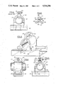
- FIG. 1 is a side elevational view of a prior art two-piece clamp assembly secured to a channel and retaining a tubing.
- FIG. 2 is a fragmentary, elevational view showing two clamp halves squarely secured together by the stud to directly clamp an elongate cylindrical member such as a pipe.
- FIG. 3 is a perspective view of a tubing clamp including an elastomeric cushion secured to a channel.
- FIG. 4 is an end elevational view showing a fragmentary portion of tubing retained within a tubing clamp assembly.
- FIG. 5 is a side elevational view showing the tubing clamp assembly.
- FIG. 6 is a partial cross-sectional view of the stud prior to assembly to a clamp half.
- FIG. 7 is a partial cross-sectional view of the pressure pad and quill forcing the clamp over the serrated portion of the stud.
- FIG. 8 is a fragmentary, cross-sectional view showing the mandrel deforming the stud to lock the stud to the clamp half.
- FIG. 9 is a partial cross-sectional view of an assembly system for automatically assembling the stud to a clamp half.
- the improved clamp assembly 21 of the present invention is generally indicated by reference numeral 21.
- the improved clamp assembly 21 comprises first and second clamp halves 23 and 24 which are detachably secured together by means of a stud 26 and an internally threaded nut 27.
- a cushion insert 29 may be provided if desired inside the first and second clamp halves 23 and 24 for indirectly engaging the tubing, or other cylindrical member through the elastomeric cushion which partially encircles the tube 12 and is retained within the clamp assembly 21.
- the unique squeeze control clamp may also be used directly against the tube 12 if it is not desireable to use the cushion insert 29.
- First and second clamp halves 23 and 24 each include an aperture 31 on one end for receiving the stud 26.
- Channel interlocking feet 32 are provided on the opposite end of each of the first and second clamp halves 23 and 24 for engaging the channel 14.
- the stud 26 is shown to include a head 34 on one end and an externally threaded end 35 on the opposite end for receiving the nut 27.
- a spacer portion 36 is provided between the head 34 and the externally threaded end 35.
- the spacer portion 36 may be an integrally formed part of the stud 26, as shown in the drawing or may be a separate member.
- the spacer portion 36 is provided to control the extent to which the first and second clamp halves 23 and 24 may be tightened.
- the spacer portion 36 includes first and second shoulders 38 and 39 which are parallel to each other and perpendicular to the axis of the stud 26.
- the first and second shoulder 38 and 39 assure that the first and second clamp halves 23 and 24 are tightened squarely to one another which eliminates the problem of deformation in prior art clamp assemblies caused by overtightening. In this way the clamp assembly provides a unique squeeze control feature that prevents deformation of the tubing which is likewised caused by overtightening prior art clamp assemblies.
- the stud 26 includes a serrated section 41 immediately adjacent the first shoulder 38.
- a pilot hole 43 is provided in the head 34 of the stud 26 to facilitate assembling the stud 26 to the first clamp half 23, as will be described in detail subsequently.
- the stud 26 is picked up by an arm 44 having a caliper gripping mechanism 45.
- the arm 44 is lifted by a cylinder 47 and rotated by an oscillating mechanism 48 which moves the arm 44 over the anvil 49.
- the cylinder 47 then lowers the stud 26 into the anvil 49.
- the arm 44 is then moved clear of the anvil 49 and returns to pick up another stud 26.
- the first clamp half 23 is then placed into a load/unload station 51 on a rotary index table 52 for assembly on to the stud 26 in the anvil 49.
- the index table 52 is rotated 180° in the disclosed embodiment to place the first clamp half 23 over the head 34 of the stud 26.
- a power cylinder 54 is actuated to drive the mandrel 56 toward the anvil 49 to assemble the first clamp half 23 and stud 26 together.
- a pressure pad 57 and quill 58 are driven against the first clamp half 23 to force the aperture 31 over the head 34 and on to the serrated section 41.
- the pressure pad 57 and quill 58 are spring loaded relative to the mandrel 56 to permit the mandrel 56 to move relative thereto.
- the mandrel 56 continues its downward motion, to the position shown in FIG. 7, until the pilot end 60 enters the pilot hole 43 in the head 34 of the stud 26.
- the mandrel 56 continues downwardly, as shown in FIG. 8, to deform, or upset, the head 34 of the stud 26 outwardly to force the serrated section 41 to grip the sides of the aperture 31 and lock the deformed portions of the head 34 into engagement with the first clamp half 23. In this way, the stud 26 is securely locked to the first clamp half 23 to prevent relative rotation between the respective parts.
- the mandrel 56 is then retracted to permit the rotary index table 52 to move the finished part out of the forming station and begin the cycle once again.
- the finished part is then ejected by a lifter 55 from the load/unload station 51, as is well known in the art.
- Springs 57 are provided to return the lifter 55 to its initial position ready for another part to be placed in the load/unload station 51.
- the first clamp half 23 is accurately and squarely assembled on the stud 26 by the coaction of the quill end 58 and pressure pad 57 since they act to drive the first clamp half 23 securely into engagement with the serrated section 41 and against the first shoulder 38. Since the first and second shoulders 38 and 39 are parallel to one another when the first and second clamp halves 23 and 24 are assembled together to form the improved clamp assembly 21 they provided a seating surface for tightening the clamp halves squarely together.
- the assembly system may be used with clamp halves made of different types of materials and there is no need to select a stud and clamp half that are compatible as would be required if the two parts were welded together. Also, if the stud were welded to the clamp half, the stud could be misaligned during welding resulting in the first and second clamp halves 23 and 24 not being square to each other when assembled together with the stud to form the clamp assembly.
Abstract
Description
Claims (4)
Priority Applications (1)
| Application Number | Priority Date | Filing Date | Title |
|---|---|---|---|
| US06/539,219 US4516296A (en) | 1983-10-05 | 1983-10-05 | Tubing clamp and method of making the same |
Applications Claiming Priority (1)
| Application Number | Priority Date | Filing Date | Title |
|---|---|---|---|
| US06/539,219 US4516296A (en) | 1983-10-05 | 1983-10-05 | Tubing clamp and method of making the same |
Publications (1)
| Publication Number | Publication Date |
|---|---|
| US4516296A true US4516296A (en) | 1985-05-14 |
Family
ID=24150321
Family Applications (1)
| Application Number | Title | Priority Date | Filing Date |
|---|---|---|---|
| US06/539,219 Expired - Lifetime US4516296A (en) | 1983-10-05 | 1983-10-05 | Tubing clamp and method of making the same |
Country Status (1)
| Country | Link |
|---|---|
| US (1) | US4516296A (en) |
Cited By (83)
| Publication number | Priority date | Publication date | Assignee | Title |
|---|---|---|---|---|
| WO1986006141A1 (en) * | 1985-04-08 | 1986-10-23 | Howard William A | Strut with inwardly depending flanges to receive and secure fittings |
| US4757965A (en) * | 1987-06-29 | 1988-07-19 | Allen C M | Conduit clamp |
| US4790060A (en) * | 1987-12-07 | 1988-12-13 | Council Jerry W | Method for holding a conduit to a channel |
| US4858861A (en) * | 1988-09-22 | 1989-08-22 | Wilkinson Iii Joseph | Clamp-type pipe shoe and method |
| US4908914A (en) * | 1989-04-14 | 1990-03-20 | Murray Corporation | Hose clamp with reproducible closure |
| US4934635A (en) * | 1988-12-20 | 1990-06-19 | Zsi, Inc. | Tubing clamp with hinged cushion |
| US4961554A (en) * | 1987-07-18 | 1990-10-09 | Ford Motor Company | Fastener |
| US4997148A (en) * | 1988-12-20 | 1991-03-05 | Zsi, Inc. | Tubing clamp with hinged cushion |
| US5014940A (en) * | 1989-08-28 | 1991-05-14 | Zsi, Inc. | Clamp assembly |
| US5141186A (en) * | 1991-07-16 | 1992-08-25 | Cusic Industries, Inc. | Pipe clamp |
| US5163644A (en) * | 1991-08-01 | 1992-11-17 | B-Line Systems, Inc. | Conduit clamp |
| US5205520A (en) * | 1992-05-26 | 1993-04-27 | Hydro-Craft, Inc. | Retaining block for clamping system |
| US5292013A (en) * | 1992-10-23 | 1994-03-08 | E-Systems, Inc. | Support ferrules |
| US5799907A (en) * | 1996-02-26 | 1998-09-01 | Andronica; Ronald | Pipe straps |
| US5855342A (en) * | 1996-10-21 | 1999-01-05 | Pipe Pier, Inc. | System for mounting elongate structures and wiring |
| US5984243A (en) * | 1997-09-09 | 1999-11-16 | Thomas & Betts International, Inc. | Pipe cushion |
| US6105216A (en) * | 1999-02-25 | 2000-08-22 | Hydra-Zorb Co. | Clamp assembly |
| US6113038A (en) * | 1997-03-14 | 2000-09-05 | Abb Daimler-Benz Transportation (Technology) Gmbh | Support for conduit |
| US6227757B1 (en) * | 1997-09-18 | 2001-05-08 | Compagnie Generale Des Matieres Nucleaires | Device for connecting two tubes together |
| US6267333B1 (en) | 1999-09-28 | 2001-07-31 | Agfa Corporation | Method and device for securing a cylindrical component to a mechanical assembly |
| US6305424B1 (en) | 1997-09-18 | 2001-10-23 | Compagnie Generale Des Matieres Nucleaires | System for supporting pipes in service galleries, especially in the nuclear industry |
| US6354542B1 (en) | 1997-02-25 | 2002-03-12 | Thomas & Betts Corporation | Modular cable tray assembly |
| US6464180B2 (en) | 2000-06-22 | 2002-10-15 | 3 North Technologies, Llc | Pipe attaching apparatus |
| US6554537B1 (en) * | 2000-11-10 | 2003-04-29 | Coflexip | Pipeline crossing module |
| US6572057B1 (en) * | 2001-01-25 | 2003-06-03 | Steven A. Roth | Hanger system for conduits and channel members |
| US6609343B1 (en) * | 2000-11-22 | 2003-08-26 | Timothy A. Litten | Open-web-joist load-support system |
| US6679461B1 (en) | 2001-04-26 | 2004-01-20 | Pipe Pier | Mounting device |
| US20040037997A1 (en) * | 2001-04-26 | 2004-02-26 | Pipe Pier | Mounting device |
| US20040040251A1 (en) * | 2002-09-03 | 2004-03-04 | Mok Chiu Pang | Device for positioning cast-in U-channels in concrete structure |
| US20040183942A1 (en) * | 1999-03-08 | 2004-09-23 | Larry Holmberg | Camera lens and display |
| GB2410295A (en) * | 2004-01-23 | 2005-07-27 | Zsi Inc | Adjustable pipe clamp assembly |
| US20050195385A1 (en) * | 2002-03-04 | 2005-09-08 | Larry Holmberg | Range finder |
| US20060027715A1 (en) * | 2004-08-05 | 2006-02-09 | Thomas & Betts International, Inc. | Pipe clamp |
| US20060038398A1 (en) * | 2004-08-23 | 2006-02-23 | Thomas & Betts International, Inc. | Scissor type pipe clamp |
| US20060091265A1 (en) * | 2004-10-28 | 2006-05-04 | Freedom, Inc. | Support block system |
| US20070045482A1 (en) * | 2005-08-31 | 2007-03-01 | Freedom, Inc. | Slotted conduit support block system |
| US20070057125A1 (en) * | 2001-04-26 | 2007-03-15 | Hawkins Patrick A | Mounting device |
| US20070120036A1 (en) * | 2005-11-30 | 2007-05-31 | Olle Raymond M | Rooftop equipment support and method of use |
| US20070157502A1 (en) * | 2006-01-06 | 2007-07-12 | Larry Holmberg | Device mount for a firearm |
| US20080000465A1 (en) * | 2006-06-30 | 2008-01-03 | Larry Holmberg | Adaptor for device mount |
| US20080001057A1 (en) * | 2006-06-30 | 2008-01-03 | Larry Holmberg | Device mount |
| US20080000463A1 (en) * | 2006-06-30 | 2008-01-03 | Larry Holmberg | Crossbow device mount |
| US20080025798A1 (en) * | 2004-06-21 | 2008-01-31 | Aco Polymer Products, Inc. | Drainage channel installation device |
| US20080087784A1 (en) * | 2006-10-17 | 2008-04-17 | Larry Holmberg | Device mount with stabilizing function |
| US20080164392A1 (en) * | 2007-01-05 | 2008-07-10 | Larry Holmberg | Device mount system for a weapon |
| US20080290653A1 (en) * | 2005-12-01 | 2008-11-27 | Uponor Innovation Ab | Pipe Coupling |
| US20090050426A1 (en) * | 2006-01-09 | 2009-02-26 | Zf Friedrichshafen Ag | Vibration Damper Comprising a Protection Against Stones |
| US20090057501A1 (en) * | 2007-09-03 | 2009-03-05 | Ming Hug Huang | Display exhibition frame |
| US20090255162A1 (en) * | 2002-03-04 | 2009-10-15 | Larry Holmberg | Range finder for weapons |
| US20090294600A1 (en) * | 2008-06-02 | 2009-12-03 | Robert Dodge | Tube clip |
| US7739822B1 (en) | 2007-01-09 | 2010-06-22 | Larry Holmberg | Method and device for mounting an accessory to a firearm |
| US7780363B1 (en) | 2008-01-17 | 2010-08-24 | Larry Holmberg | Device for mounting imaging equipment to a bow and method of recording a hunt |
| US20100301178A1 (en) * | 2009-05-27 | 2010-12-02 | Philip Allen Myers | Building strut system |
| US20100313462A1 (en) * | 2009-06-16 | 2010-12-16 | Lary Holmberg | Electronic device mount system for weapons |
| US20110113672A1 (en) * | 2009-11-19 | 2011-05-19 | Larry Holmberg | Remote controlled decoy |
| US8156680B2 (en) | 2002-03-04 | 2012-04-17 | Larry Holmberg | Device mounting system for a weapon |
| US8161674B2 (en) | 2009-06-16 | 2012-04-24 | Larry Holmberg | Electronic device mount system with strap |
| US20120181412A1 (en) * | 2011-01-19 | 2012-07-19 | The Pullman Company | Isolator having socket mounting |
| US8656624B2 (en) | 2010-12-29 | 2014-02-25 | Larry Holmberg | Universal device mount |
| US8656625B2 (en) | 2010-12-29 | 2014-02-25 | Larry Holmberg | Accessory mount |
| US20140263895A1 (en) * | 2009-05-13 | 2014-09-18 | Daniel James Dickenson | Magnetic bracket and method |
| US20140283462A1 (en) * | 2013-03-14 | 2014-09-25 | Cooper Technologies Company | Conduit clamp for channel framing |
| GB2514242A (en) * | 2013-03-15 | 2014-11-19 | Zsi Inc | Cushion insert for a tubing clamp and method of replacement |
| US20140356048A1 (en) * | 2013-06-04 | 2014-12-04 | Yu-Hung Chou | Universal connector |
| USD735025S1 (en) * | 2014-01-28 | 2015-07-28 | Behringer Corporation | Hygienic clamp |
| USD747181S1 (en) * | 2013-01-16 | 2016-01-12 | Susumu Hikoyama | Angled pipe clamp |
| US9347213B1 (en) | 2014-11-14 | 2016-05-24 | Cooper Technologies Company | Fitting for channel framing |
| US9347589B1 (en) * | 2008-10-22 | 2016-05-24 | Lawrence S. Cohen | Strut clamp |
| US9458952B2 (en) | 2014-04-30 | 2016-10-04 | Cooper Technologies Company | Trapeze hanger system including twist-locking fitting |
| US9546744B2 (en) | 2014-05-02 | 2017-01-17 | Cooper Technologies Company | Conduit clamp for strut channel |
| US9574589B2 (en) | 2014-04-30 | 2017-02-21 | Cooper Technologies Company | Trapeze hanger system including trapeze hanger fitting |
| US9683590B2 (en) | 2014-05-02 | 2017-06-20 | Cooper Technologies Company | Strut system and strut fitting therefor |
| CN107208826A (en) * | 2015-02-13 | 2017-09-26 | J·范瓦尔拉芬私人控股有限公司 | Pipe clamp |
| US9790980B2 (en) | 2013-12-23 | 2017-10-17 | Cooper Technologies Company | Fastener nut for channel framing |
| US9903512B2 (en) * | 2015-05-26 | 2018-02-27 | Georg Fischer Llc | Pipe clamp for strut system |
| US9926957B2 (en) | 2014-11-14 | 2018-03-27 | Cooper Technologies Company | Fitting for strut channel |
| US9982695B2 (en) | 2014-11-14 | 2018-05-29 | Cooper Technologies Company | Fitting for strut channel |
| US10100861B2 (en) | 2014-11-14 | 2018-10-16 | Cooper Technologies Company | Beam clamp for strut channel |
| US20180347724A1 (en) * | 2015-12-07 | 2018-12-06 | J. Van Walraven Holding B.V. | Pipe clamp for a range of pipe diameters |
| US20190077439A1 (en) * | 2016-03-17 | 2019-03-14 | Thyssenkrupp Presta Ag | Steering column for a motor vehicle and method for producing a steering column |
| US10294675B2 (en) * | 2016-11-10 | 2019-05-21 | Hunter Douglas Industries B.V. | Bracket for mounting a panel to a carrier |
| JP2019131008A (en) * | 2018-01-30 | 2019-08-08 | ミネベアミツミ株式会社 | Wheel module and movement mechanism |
| US10947724B2 (en) | 2018-07-04 | 2021-03-16 | Hunter Douglas Industries B.V. | Ceiling system |
Citations (32)
| Publication number | Priority date | Publication date | Assignee | Title |
|---|---|---|---|---|
| US1668953A (en) * | 1926-04-10 | 1928-05-08 | Frederic W Erickson | Molding for electric cables |
| US1778350A (en) * | 1929-05-10 | 1930-10-14 | George B Bosco | Clamp for adjustable shores |
| US1919219A (en) * | 1931-08-22 | 1933-07-25 | Tabulating Machine Co | Card printing and punching mechanism |
| US2345650A (en) * | 1940-10-12 | 1944-04-04 | Charles W Attwood | Skeletonized structure |
| US2359209A (en) * | 1942-08-18 | 1944-09-26 | Adel Prec Products Corp | Clip for supporting conduits |
| US2440469A (en) * | 1944-10-23 | 1948-04-27 | Adel Prec Products Corp | Multiple clip and bracket |
| US2470814A (en) * | 1948-03-04 | 1949-05-24 | Hain Max | Electrical cable support or rack |
| US2535427A (en) * | 1946-04-02 | 1950-12-26 | Kindorf Co | Conduit supporting frame |
| US2648246A (en) * | 1949-04-07 | 1953-08-11 | Walter W Mueller | Ligature for musical instruments |
| US2676680A (en) * | 1952-02-05 | 1954-04-27 | Orlan C Kindorf | Beam structure and associated securing means |
| US2697570A (en) * | 1951-05-01 | 1954-12-21 | Thompson Prod Inc | Quick-attaching device |
| GB757560A (en) * | 1953-12-09 | 1956-09-19 | Portable Ind Inc | Improvements in or relating to studs adapted to be explosively driven into walls |
| US2866372A (en) * | 1954-03-08 | 1958-12-30 | Fisher Ind Inc | Bolt non-rotatively secured to plate by struck out shank portion |
| US2897569A (en) * | 1958-12-08 | 1959-08-04 | L C Thomsen & Sons Inc | Clamps |
| US2918239A (en) * | 1956-05-16 | 1959-12-22 | Martin Co | Expansion-permitting hanger |
| US2961210A (en) * | 1956-10-01 | 1960-11-22 | Olin Mathieson | Fastening assembly |
| US2983897A (en) * | 1957-12-11 | 1961-05-09 | Bar-carried detachable electrical terminal blocks | |
| US2987752A (en) * | 1958-11-10 | 1961-06-13 | Pemco Wheel Co | Caster |
| US2998217A (en) * | 1959-07-06 | 1961-08-29 | T A Mfg Corp | Quick-opening line supporting clamp |
| US3058211A (en) * | 1958-09-29 | 1962-10-16 | Harold B Axtell | Method and apparatus for securing a stud or screw |
| US3245449A (en) * | 1964-04-09 | 1966-04-12 | Nat Lock Co | Speaker mounting screw |
| US3291426A (en) * | 1965-12-03 | 1966-12-13 | Celanese Building Components L | Pipe mounting |
| US3301514A (en) * | 1964-09-30 | 1967-01-31 | Sugaya Masao | Clips for conduits or pipes |
| US3346286A (en) * | 1965-08-31 | 1967-10-10 | Burroughs Corp | Component mounting employing a threaded bolt driven at its threaded end |
| US3362449A (en) * | 1965-09-20 | 1968-01-09 | Mc Graw Edison Co | Static-free bolt |
| US3370815A (en) * | 1965-09-13 | 1968-02-27 | Lamb Co F Jos | Shock absorbing pad for conduit clamping device |
| US3429014A (en) * | 1967-12-04 | 1969-02-25 | Castle Ind Inc Of California | Clamp assembly for confronting annular flanges |
| US3431960A (en) * | 1966-10-10 | 1969-03-11 | Robert Neuschotz | Threaded fastener with deformable anchoring portion |
| US3809584A (en) * | 1972-01-28 | 1974-05-07 | Sumitomo Electric Industries | Method for continuously growing epitaxial layers of semiconductors from liquid phase |
| US3924317A (en) * | 1972-08-18 | 1975-12-09 | Trw Inc | Method of coupling the components of a molding retainer |
| US4007540A (en) * | 1973-09-21 | 1977-02-15 | Lockheed Aircraft Corporation | Method for fabricating a cavity rivet assembly |
| US4185802A (en) * | 1978-09-13 | 1980-01-29 | Fischer Sherman, Inc. | Anti-vibration pad for pipe support clamp |
-
1983
- 1983-10-05 US US06/539,219 patent/US4516296A/en not_active Expired - Lifetime
Patent Citations (32)
| Publication number | Priority date | Publication date | Assignee | Title |
|---|---|---|---|---|
| US1668953A (en) * | 1926-04-10 | 1928-05-08 | Frederic W Erickson | Molding for electric cables |
| US1778350A (en) * | 1929-05-10 | 1930-10-14 | George B Bosco | Clamp for adjustable shores |
| US1919219A (en) * | 1931-08-22 | 1933-07-25 | Tabulating Machine Co | Card printing and punching mechanism |
| US2345650A (en) * | 1940-10-12 | 1944-04-04 | Charles W Attwood | Skeletonized structure |
| US2359209A (en) * | 1942-08-18 | 1944-09-26 | Adel Prec Products Corp | Clip for supporting conduits |
| US2440469A (en) * | 1944-10-23 | 1948-04-27 | Adel Prec Products Corp | Multiple clip and bracket |
| US2535427A (en) * | 1946-04-02 | 1950-12-26 | Kindorf Co | Conduit supporting frame |
| US2470814A (en) * | 1948-03-04 | 1949-05-24 | Hain Max | Electrical cable support or rack |
| US2648246A (en) * | 1949-04-07 | 1953-08-11 | Walter W Mueller | Ligature for musical instruments |
| US2697570A (en) * | 1951-05-01 | 1954-12-21 | Thompson Prod Inc | Quick-attaching device |
| US2676680A (en) * | 1952-02-05 | 1954-04-27 | Orlan C Kindorf | Beam structure and associated securing means |
| GB757560A (en) * | 1953-12-09 | 1956-09-19 | Portable Ind Inc | Improvements in or relating to studs adapted to be explosively driven into walls |
| US2866372A (en) * | 1954-03-08 | 1958-12-30 | Fisher Ind Inc | Bolt non-rotatively secured to plate by struck out shank portion |
| US2918239A (en) * | 1956-05-16 | 1959-12-22 | Martin Co | Expansion-permitting hanger |
| US2961210A (en) * | 1956-10-01 | 1960-11-22 | Olin Mathieson | Fastening assembly |
| US2983897A (en) * | 1957-12-11 | 1961-05-09 | Bar-carried detachable electrical terminal blocks | |
| US3058211A (en) * | 1958-09-29 | 1962-10-16 | Harold B Axtell | Method and apparatus for securing a stud or screw |
| US2987752A (en) * | 1958-11-10 | 1961-06-13 | Pemco Wheel Co | Caster |
| US2897569A (en) * | 1958-12-08 | 1959-08-04 | L C Thomsen & Sons Inc | Clamps |
| US2998217A (en) * | 1959-07-06 | 1961-08-29 | T A Mfg Corp | Quick-opening line supporting clamp |
| US3245449A (en) * | 1964-04-09 | 1966-04-12 | Nat Lock Co | Speaker mounting screw |
| US3301514A (en) * | 1964-09-30 | 1967-01-31 | Sugaya Masao | Clips for conduits or pipes |
| US3346286A (en) * | 1965-08-31 | 1967-10-10 | Burroughs Corp | Component mounting employing a threaded bolt driven at its threaded end |
| US3370815A (en) * | 1965-09-13 | 1968-02-27 | Lamb Co F Jos | Shock absorbing pad for conduit clamping device |
| US3362449A (en) * | 1965-09-20 | 1968-01-09 | Mc Graw Edison Co | Static-free bolt |
| US3291426A (en) * | 1965-12-03 | 1966-12-13 | Celanese Building Components L | Pipe mounting |
| US3431960A (en) * | 1966-10-10 | 1969-03-11 | Robert Neuschotz | Threaded fastener with deformable anchoring portion |
| US3429014A (en) * | 1967-12-04 | 1969-02-25 | Castle Ind Inc Of California | Clamp assembly for confronting annular flanges |
| US3809584A (en) * | 1972-01-28 | 1974-05-07 | Sumitomo Electric Industries | Method for continuously growing epitaxial layers of semiconductors from liquid phase |
| US3924317A (en) * | 1972-08-18 | 1975-12-09 | Trw Inc | Method of coupling the components of a molding retainer |
| US4007540A (en) * | 1973-09-21 | 1977-02-15 | Lockheed Aircraft Corporation | Method for fabricating a cavity rivet assembly |
| US4185802A (en) * | 1978-09-13 | 1980-01-29 | Fischer Sherman, Inc. | Anti-vibration pad for pipe support clamp |
Cited By (155)
| Publication number | Priority date | Publication date | Assignee | Title |
|---|---|---|---|---|
| WO1986006141A1 (en) * | 1985-04-08 | 1986-10-23 | Howard William A | Strut with inwardly depending flanges to receive and secure fittings |
| US4708554A (en) * | 1985-04-08 | 1987-11-24 | Howard William A | Strut |
| US4757965A (en) * | 1987-06-29 | 1988-07-19 | Allen C M | Conduit clamp |
| US4961554A (en) * | 1987-07-18 | 1990-10-09 | Ford Motor Company | Fastener |
| US4790060A (en) * | 1987-12-07 | 1988-12-13 | Council Jerry W | Method for holding a conduit to a channel |
| US4858861A (en) * | 1988-09-22 | 1989-08-22 | Wilkinson Iii Joseph | Clamp-type pipe shoe and method |
| US4934635A (en) * | 1988-12-20 | 1990-06-19 | Zsi, Inc. | Tubing clamp with hinged cushion |
| US4997148A (en) * | 1988-12-20 | 1991-03-05 | Zsi, Inc. | Tubing clamp with hinged cushion |
| US4908914A (en) * | 1989-04-14 | 1990-03-20 | Murray Corporation | Hose clamp with reproducible closure |
| US5014940A (en) * | 1989-08-28 | 1991-05-14 | Zsi, Inc. | Clamp assembly |
| US5141186A (en) * | 1991-07-16 | 1992-08-25 | Cusic Industries, Inc. | Pipe clamp |
| US5163644A (en) * | 1991-08-01 | 1992-11-17 | B-Line Systems, Inc. | Conduit clamp |
| US5205520A (en) * | 1992-05-26 | 1993-04-27 | Hydro-Craft, Inc. | Retaining block for clamping system |
| US5292013A (en) * | 1992-10-23 | 1994-03-08 | E-Systems, Inc. | Support ferrules |
| US5799907A (en) * | 1996-02-26 | 1998-09-01 | Andronica; Ronald | Pipe straps |
| US5855342A (en) * | 1996-10-21 | 1999-01-05 | Pipe Pier, Inc. | System for mounting elongate structures and wiring |
| US6305650B1 (en) * | 1996-10-21 | 2001-10-23 | Pipe Pier | System for mounting elongate structures and wiring |
| US6354542B1 (en) | 1997-02-25 | 2002-03-12 | Thomas & Betts Corporation | Modular cable tray assembly |
| US6113038A (en) * | 1997-03-14 | 2000-09-05 | Abb Daimler-Benz Transportation (Technology) Gmbh | Support for conduit |
| US5984243A (en) * | 1997-09-09 | 1999-11-16 | Thomas & Betts International, Inc. | Pipe cushion |
| US6227757B1 (en) * | 1997-09-18 | 2001-05-08 | Compagnie Generale Des Matieres Nucleaires | Device for connecting two tubes together |
| US6305424B1 (en) | 1997-09-18 | 2001-10-23 | Compagnie Generale Des Matieres Nucleaires | System for supporting pipes in service galleries, especially in the nuclear industry |
| US6105216A (en) * | 1999-02-25 | 2000-08-22 | Hydra-Zorb Co. | Clamp assembly |
| US8045038B2 (en) | 1999-03-08 | 2011-10-25 | Larry Holmberg | Video camera with mount |
| US8035735B2 (en) | 1999-03-08 | 2011-10-11 | Larry Holmberg | Camera with weather cover |
| US9521300B2 (en) | 1999-03-08 | 2016-12-13 | Larry Holmberg | Camera for mounting |
| US8717496B2 (en) | 1999-03-08 | 2014-05-06 | Larry Holmberg | Rail mount |
| US7965337B2 (en) | 1999-03-08 | 2011-06-21 | Larry Holmberg | System for mounting camera on bow |
| US20090237556A1 (en) * | 1999-03-08 | 2009-09-24 | Larry Holmberg | Camera with weather cover |
| US20100128166A1 (en) * | 1999-03-08 | 2010-05-27 | Larry Holmberg | Camera for mounting |
| US8059196B2 (en) | 1999-03-08 | 2011-11-15 | Larry Holmberg | Camera for mounting |
| US20040183942A1 (en) * | 1999-03-08 | 2004-09-23 | Larry Holmberg | Camera lens and display |
| US20100066899A1 (en) * | 1999-03-08 | 2010-03-18 | Larry Holmberg | Video camera with mount |
| US8717497B2 (en) | 1999-03-08 | 2014-05-06 | Larry Holmberg | Camera for mounting |
| US9143663B2 (en) | 1999-03-08 | 2015-09-22 | Larry Holmberg | Camera for mounting |
| US7880793B2 (en) | 1999-03-08 | 2011-02-01 | Larry Holmberg | Camera with mounting rail |
| US7619676B2 (en) | 1999-03-08 | 2009-11-17 | Larry Holmberg | Camera lens and display |
| US20090244362A1 (en) * | 1999-03-08 | 2009-10-01 | Larry Holmberg | System for mounting camera on bow |
| US20090244326A1 (en) * | 1999-03-08 | 2009-10-01 | Larry Holmberg | Camera with mounting rail |
| US6267333B1 (en) | 1999-09-28 | 2001-07-31 | Agfa Corporation | Method and device for securing a cylindrical component to a mechanical assembly |
| US6464180B2 (en) | 2000-06-22 | 2002-10-15 | 3 North Technologies, Llc | Pipe attaching apparatus |
| US6554537B1 (en) * | 2000-11-10 | 2003-04-29 | Coflexip | Pipeline crossing module |
| US6609343B1 (en) * | 2000-11-22 | 2003-08-26 | Timothy A. Litten | Open-web-joist load-support system |
| US6572057B1 (en) * | 2001-01-25 | 2003-06-03 | Steven A. Roth | Hanger system for conduits and channel members |
| US7708235B2 (en) | 2001-04-26 | 2010-05-04 | Pipe Pier | Mounting device |
| US20070057125A1 (en) * | 2001-04-26 | 2007-03-15 | Hawkins Patrick A | Mounting device |
| US7922130B2 (en) | 2001-04-26 | 2011-04-12 | Pipe Pier | Mounting device |
| US20100258700A1 (en) * | 2001-04-26 | 2010-10-14 | Pipe Pier | Mounting device |
| US20040037997A1 (en) * | 2001-04-26 | 2004-02-26 | Pipe Pier | Mounting device |
| US6679461B1 (en) | 2001-04-26 | 2004-01-20 | Pipe Pier | Mounting device |
| US8240077B2 (en) | 2002-03-04 | 2012-08-14 | Larry Holmberg | Range finder for weapons |
| US7643132B2 (en) | 2002-03-04 | 2010-01-05 | Larry Holmberg | Range finder |
| US20100071247A1 (en) * | 2002-03-04 | 2010-03-25 | Larry Holmberg | Range finder |
| US20050195385A1 (en) * | 2002-03-04 | 2005-09-08 | Larry Holmberg | Range finder |
| US8156680B2 (en) | 2002-03-04 | 2012-04-17 | Larry Holmberg | Device mounting system for a weapon |
| US20090255162A1 (en) * | 2002-03-04 | 2009-10-15 | Larry Holmberg | Range finder for weapons |
| US7982858B2 (en) | 2002-03-04 | 2011-07-19 | Larry Holmberg | Range finder |
| US8656629B2 (en) | 2002-03-04 | 2014-02-25 | Larry Holmberg | Range finder for weapons |
| US6817156B2 (en) * | 2002-09-03 | 2004-11-16 | Chiu Pang Mok | Device for positioning cast-in U-channels in concrete structure |
| US20040040251A1 (en) * | 2002-09-03 | 2004-03-04 | Mok Chiu Pang | Device for positioning cast-in U-channels in concrete structure |
| US20050163561A1 (en) * | 2004-01-23 | 2005-07-28 | Weger Kris A. | Adjustable pipe clamp assembly |
| US7179010B2 (en) | 2004-01-23 | 2007-02-20 | Zsi, Inc. | Adjustable pipe clamp assembly |
| US20070034752A1 (en) * | 2004-01-23 | 2007-02-15 | Zsi, Inc. | Adjustable pipe clamp assembly |
| GB2410295A (en) * | 2004-01-23 | 2005-07-27 | Zsi Inc | Adjustable pipe clamp assembly |
| GB2410295B (en) * | 2004-01-23 | 2008-09-03 | Zsi Inc | Adjustable pipe clamp assembly |
| US7506844B2 (en) * | 2004-06-21 | 2009-03-24 | Aco Polymer Products, Inc. | Drainage channel installation device |
| US20080025798A1 (en) * | 2004-06-21 | 2008-01-31 | Aco Polymer Products, Inc. | Drainage channel installation device |
| US20060027715A1 (en) * | 2004-08-05 | 2006-02-09 | Thomas & Betts International, Inc. | Pipe clamp |
| US7591442B2 (en) | 2004-08-05 | 2009-09-22 | Thomas & Betts International, Inc. | Pipe clamp |
| US8091839B2 (en) | 2004-08-23 | 2012-01-10 | Thomas & Betts International, Inc. | Scissor type pipe clamp |
| US20060038398A1 (en) * | 2004-08-23 | 2006-02-23 | Thomas & Betts International, Inc. | Scissor type pipe clamp |
| US20060091265A1 (en) * | 2004-10-28 | 2006-05-04 | Freedom, Inc. | Support block system |
| US7441731B2 (en) * | 2004-10-28 | 2008-10-28 | Smart Kenneth L | Support block system |
| US7607619B2 (en) * | 2005-08-31 | 2009-10-27 | Freedom, Inc. | Slotted conduit support block system |
| US20070045482A1 (en) * | 2005-08-31 | 2007-03-01 | Freedom, Inc. | Slotted conduit support block system |
| US7735270B2 (en) | 2005-11-30 | 2010-06-15 | Erico International Corporation | Rooftop equipment support and method of use |
| US20070120036A1 (en) * | 2005-11-30 | 2007-05-31 | Olle Raymond M | Rooftop equipment support and method of use |
| US20080290653A1 (en) * | 2005-12-01 | 2008-11-27 | Uponor Innovation Ab | Pipe Coupling |
| US7753414B2 (en) * | 2005-12-01 | 2010-07-13 | Uponor Innovation Ab | Pipe coupling |
| US7574824B2 (en) | 2006-01-06 | 2009-08-18 | Larry Holmberg | Device mount for a firearm |
| US20070157502A1 (en) * | 2006-01-06 | 2007-07-12 | Larry Holmberg | Device mount for a firearm |
| US8046950B2 (en) | 2006-01-06 | 2011-11-01 | Larry Holmberg | Method of attaching device to weapon |
| US20100018103A1 (en) * | 2006-01-06 | 2010-01-28 | Larry Holmberg | Method of attaching device to weapon |
| US20090050426A1 (en) * | 2006-01-09 | 2009-02-26 | Zf Friedrichshafen Ag | Vibration Damper Comprising a Protection Against Stones |
| US7647922B2 (en) * | 2006-06-30 | 2010-01-19 | Larry Holmberg | Adaptor for device mount |
| US20080000465A1 (en) * | 2006-06-30 | 2008-01-03 | Larry Holmberg | Adaptor for device mount |
| US20080000463A1 (en) * | 2006-06-30 | 2008-01-03 | Larry Holmberg | Crossbow device mount |
| US8065994B2 (en) | 2006-06-30 | 2011-11-29 | Larry Holmberg | Adaptor for device mount |
| US7886733B2 (en) | 2006-06-30 | 2011-02-15 | Larry Holmberg | Method of mounting an autonomous electronic device on to a crossbow |
| US7506643B2 (en) | 2006-06-30 | 2009-03-24 | Larry Holmberg | Crossbow device mount |
| US20080001057A1 (en) * | 2006-06-30 | 2008-01-03 | Larry Holmberg | Device mount |
| US20090183353A1 (en) * | 2006-06-30 | 2009-07-23 | Larry Holmberg | Method of mounting an autonomous electronic device on to a crossbow |
| US20080087784A1 (en) * | 2006-10-17 | 2008-04-17 | Larry Holmberg | Device mount with stabilizing function |
| US7926220B2 (en) | 2006-10-17 | 2011-04-19 | Larry Holmberg | Stabilizing device mount and method |
| US7594352B2 (en) | 2006-10-17 | 2009-09-29 | Larry Holmberg | Device mount with stabilizing function |
| US20080164392A1 (en) * | 2007-01-05 | 2008-07-10 | Larry Holmberg | Device mount system for a weapon |
| US7891131B2 (en) | 2007-01-05 | 2011-02-22 | Larry Holmberg | Device mount system for a weapon |
| US7739822B1 (en) | 2007-01-09 | 2010-06-22 | Larry Holmberg | Method and device for mounting an accessory to a firearm |
| US20090057501A1 (en) * | 2007-09-03 | 2009-03-05 | Ming Hug Huang | Display exhibition frame |
| US7780363B1 (en) | 2008-01-17 | 2010-08-24 | Larry Holmberg | Device for mounting imaging equipment to a bow and method of recording a hunt |
| US7784745B2 (en) * | 2008-06-02 | 2010-08-31 | Robert Dodge | Tube clip |
| US20090294600A1 (en) * | 2008-06-02 | 2009-12-03 | Robert Dodge | Tube clip |
| US9347589B1 (en) * | 2008-10-22 | 2016-05-24 | Lawrence S. Cohen | Strut clamp |
| US10429000B2 (en) * | 2009-05-13 | 2019-10-01 | Termax Llc | Magnetic bracket and method |
| US20140263895A1 (en) * | 2009-05-13 | 2014-09-18 | Daniel James Dickenson | Magnetic bracket and method |
| US8714495B2 (en) | 2009-05-27 | 2014-05-06 | Philip Allen Myers | Building strut system |
| US20100301178A1 (en) * | 2009-05-27 | 2010-12-02 | Philip Allen Myers | Building strut system |
| US8161674B2 (en) | 2009-06-16 | 2012-04-24 | Larry Holmberg | Electronic device mount system with strap |
| US20100313462A1 (en) * | 2009-06-16 | 2010-12-16 | Lary Holmberg | Electronic device mount system for weapons |
| US8024884B2 (en) | 2009-06-16 | 2011-09-27 | Larry Holmberg | Electronic device mount system for weapons |
| US20110113672A1 (en) * | 2009-11-19 | 2011-05-19 | Larry Holmberg | Remote controlled decoy |
| US8656624B2 (en) | 2010-12-29 | 2014-02-25 | Larry Holmberg | Universal device mount |
| US8656625B2 (en) | 2010-12-29 | 2014-02-25 | Larry Holmberg | Accessory mount |
| US8366069B2 (en) * | 2011-01-19 | 2013-02-05 | The Pullman Company | Isolator having socket mounting |
| US20120181412A1 (en) * | 2011-01-19 | 2012-07-19 | The Pullman Company | Isolator having socket mounting |
| USD747181S1 (en) * | 2013-01-16 | 2016-01-12 | Susumu Hikoyama | Angled pipe clamp |
| US9453592B2 (en) | 2013-03-14 | 2016-09-27 | Cooper Technologies Company | Fitting including clip for channel framing |
| US9587767B2 (en) | 2013-03-14 | 2017-03-07 | Cooper Technology Company | Fitting for trapeze hanger |
| US10619791B2 (en) | 2013-03-14 | 2020-04-14 | Eaton Intelligent Power Limited | Channel framing with additional functional side |
| US9470339B2 (en) | 2013-03-14 | 2016-10-18 | Cooper Technologies Company | Fitting for connecting two pieces of channel framing to one another |
| US20140283462A1 (en) * | 2013-03-14 | 2014-09-25 | Cooper Technologies Company | Conduit clamp for channel framing |
| US9982837B2 (en) | 2013-03-14 | 2018-05-29 | Cooper Technologies Company | Fitting including clip for channel framing |
| US9746105B2 (en) * | 2013-03-14 | 2017-08-29 | Cooper Technologies Company | Conduit clamp for channel framing |
| US9651171B2 (en) | 2013-03-14 | 2017-05-16 | Cooper Technologies Company | Nut-washer assembly for channel framing |
| GB2514242B (en) * | 2013-03-15 | 2020-02-19 | Zsi Foster Inc | Cushion insert for a tubing clamp and method of replacement |
| US9074715B2 (en) | 2013-03-15 | 2015-07-07 | Zsi, Inc. | Cushion insert for a tubing clamp and method of replacement |
| GB2514242A (en) * | 2013-03-15 | 2014-11-19 | Zsi Inc | Cushion insert for a tubing clamp and method of replacement |
| US20140356048A1 (en) * | 2013-06-04 | 2014-12-04 | Yu-Hung Chou | Universal connector |
| US9790980B2 (en) | 2013-12-23 | 2017-10-17 | Cooper Technologies Company | Fastener nut for channel framing |
| USD735025S1 (en) * | 2014-01-28 | 2015-07-28 | Behringer Corporation | Hygienic clamp |
| US9732887B2 (en) | 2014-04-30 | 2017-08-15 | Cooper Technologies Company | Trapeze hanger system including twist-locking fitting |
| US9574589B2 (en) | 2014-04-30 | 2017-02-21 | Cooper Technologies Company | Trapeze hanger system including trapeze hanger fitting |
| US9458952B2 (en) | 2014-04-30 | 2016-10-04 | Cooper Technologies Company | Trapeze hanger system including twist-locking fitting |
| US10012255B2 (en) | 2014-04-30 | 2018-07-03 | Cooper Technologies Company | Trapeze hanger system including trapeze hanger fitting |
| US9546744B2 (en) | 2014-05-02 | 2017-01-17 | Cooper Technologies Company | Conduit clamp for strut channel |
| US9683590B2 (en) | 2014-05-02 | 2017-06-20 | Cooper Technologies Company | Strut system and strut fitting therefor |
| US9989169B2 (en) | 2014-05-02 | 2018-06-05 | Cooper Technologies Company | Conduit clamp for strut channel |
| US10100861B2 (en) | 2014-11-14 | 2018-10-16 | Cooper Technologies Company | Beam clamp for strut channel |
| US9982695B2 (en) | 2014-11-14 | 2018-05-29 | Cooper Technologies Company | Fitting for strut channel |
| US9926957B2 (en) | 2014-11-14 | 2018-03-27 | Cooper Technologies Company | Fitting for strut channel |
| US9580900B2 (en) | 2014-11-14 | 2017-02-28 | Cooper Technologies Company | Fitting for channel framing |
| US10161127B2 (en) | 2014-11-14 | 2018-12-25 | Cooper Technologies Company | Fitting for channel framing |
| US9347213B1 (en) | 2014-11-14 | 2016-05-24 | Cooper Technologies Company | Fitting for channel framing |
| AU2016218510B2 (en) * | 2015-02-13 | 2020-07-30 | J. Van Walraven Holding B.V. | Pipe clamp |
| CN107208826A (en) * | 2015-02-13 | 2017-09-26 | J·范瓦尔拉芬私人控股有限公司 | Pipe clamp |
| US9903512B2 (en) * | 2015-05-26 | 2018-02-27 | Georg Fischer Llc | Pipe clamp for strut system |
| US10428975B2 (en) * | 2015-12-07 | 2019-10-01 | J. Van Walraven Holding B.V. | Pipe clamp for a range of pipe diameters |
| US20180347724A1 (en) * | 2015-12-07 | 2018-12-06 | J. Van Walraven Holding B.V. | Pipe clamp for a range of pipe diameters |
| US20190077439A1 (en) * | 2016-03-17 | 2019-03-14 | Thyssenkrupp Presta Ag | Steering column for a motor vehicle and method for producing a steering column |
| US10780911B2 (en) * | 2016-03-17 | 2020-09-22 | Thyssenkrupp Presta Ag | Steering column for a motor vehicle and method for producing a steering column |
| US10294675B2 (en) * | 2016-11-10 | 2019-05-21 | Hunter Douglas Industries B.V. | Bracket for mounting a panel to a carrier |
| JP2019131008A (en) * | 2018-01-30 | 2019-08-08 | ミネベアミツミ株式会社 | Wheel module and movement mechanism |
| JP7201323B2 (en) | 2018-01-30 | 2023-01-10 | ミネベアミツミ株式会社 | Wheel module and travel mechanism |
| US10947724B2 (en) | 2018-07-04 | 2021-03-16 | Hunter Douglas Industries B.V. | Ceiling system |
| US11634907B2 (en) | 2018-07-04 | 2023-04-25 | Hunter Douglas Industries B.V. | Ceiling system |
Similar Documents
| Publication | Publication Date | Title |
|---|---|---|
| US4516296A (en) | Tubing clamp and method of making the same | |
| US3938239A (en) | Method of forming a self-flanging nut joint | |
| US3750452A (en) | Collet crimper | |
| US2955505A (en) | Pin with enlarged rib to provide prestressing | |
| US4969785A (en) | Fastener mandrel and method | |
| CA2630632A1 (en) | Method for introducing and anchoring at least one connecting element into and in a workpiece and device for carrying out said method | |
| US20060170142A1 (en) | Hole-filling three-prong temporary fastener | |
| JP2001510732A (en) | Method and apparatus for forming a rivet joint | |
| US6941651B2 (en) | Pulley and bearing assembly and a method and apparatus for inserting and fastening a bearing within a pulley | |
| US4309892A (en) | Crimping machine | |
| US6862789B1 (en) | Assembly tool | |
| CN113905849B (en) | Setting tool for blind fasteners | |
| US4611381A (en) | Method of joining two or more pieces of malleable material | |
| EP1000697B1 (en) | Gripper | |
| US4649733A (en) | Punch with compression sleeve | |
| US5080313A (en) | Pipe to plate connection | |
| US6543817B1 (en) | Process for forming radially upset tube flange and tube connector assembly formed thereby | |
| EP1322437B1 (en) | Swaged tube fitting collar and die | |
| JP2923315B2 (en) | Swaging tool | |
| EP1176111A2 (en) | Wooden spool held together with novel tie rod assembly and method of assembling the same between a pair of dies | |
| JPS6331288B2 (en) | ||
| JPH0428447B2 (en) | ||
| US6450002B1 (en) | Compact apparatus for grooving a tube and method for grooving a tube | |
| JPH01249274A (en) | Method for fitting welding bolt | |
| US6691546B1 (en) | Rivet nut setting tool |
Legal Events
| Date | Code | Title | Description |
|---|---|---|---|
| AS | Assignment |
Owner name: ZSI INC., 12700 ROYAL GRAND, REDFORD MI 48239 Free format text: ASSIGNMENT OF ASSIGNORS INTEREST.;ASSIGNOR:SHERMAN, CLARENCE A.;REEL/FRAME:004183/0390 Effective date: 19830926 |
|
| STCF | Information on status: patent grant |
Free format text: PATENTED CASE |
|
| FEPP | Fee payment procedure |
Free format text: PAYOR NUMBER ASSIGNED (ORIGINAL EVENT CODE: ASPN); ENTITY STATUS OF PATENT OWNER: SMALL ENTITY |
|
| FPAY | Fee payment |
Year of fee payment: 4 |
|
| FEPP | Fee payment procedure |
Free format text: PAYOR NUMBER ASSIGNED (ORIGINAL EVENT CODE: ASPN); ENTITY STATUS OF PATENT OWNER: SMALL ENTITY Free format text: PAYER NUMBER DE-ASSIGNED (ORIGINAL EVENT CODE: RMPN); ENTITY STATUS OF PATENT OWNER: SMALL ENTITY |
|
| FPAY | Fee payment |
Year of fee payment: 8 |
|
| FPAY | Fee payment |
Year of fee payment: 12 |
|
| AS | Assignment |
Owner name: HORIZON INVESTMENT COMPANY, LLC, MICHIGAN Free format text: ASSIGNMENT OF ASSIGNORS INTEREST;ASSIGNOR:ZSI, INC.;REEL/FRAME:008943/0125 Effective date: 19980106 |
|
| AS | Assignment |
Owner name: ZSI, INC., MICHIGAN Free format text: MERGER AND CHANGE OF NAME;ASSIGNOR:ZSI, LLC;REEL/FRAME:015098/0704 Effective date: 20011227 Owner name: ZSI, LLC, MICHIGAN Free format text: CHANGE OF NAME;ASSIGNOR:HORIZON INVESTMENT COMPANY, LLC;REEL/FRAME:014964/0668 Effective date: 19980101 |