US4516691A - Pierce turn tap - Google Patents
Pierce turn tap Download PDFInfo
- Publication number
- US4516691A US4516691A US06/342,660 US34266082A US4516691A US 4516691 A US4516691 A US 4516691A US 34266082 A US34266082 A US 34266082A US 4516691 A US4516691 A US 4516691A
- Authority
- US
- United States
- Prior art keywords
- tap
- pierce
- pouch
- piercer
- sleeve
- Prior art date
- Legal status (The legal status is an assumption and is not a legal conclusion. Google has not performed a legal analysis and makes no representation as to the accuracy of the status listed.)
- Expired - Lifetime
Links
Images

Classifications
-
- B—PERFORMING OPERATIONS; TRANSPORTING
- B67—OPENING, CLOSING OR CLEANING BOTTLES, JARS OR SIMILAR CONTAINERS; LIQUID HANDLING
- B67B—APPLYING CLOSURE MEMBERS TO BOTTLES JARS, OR SIMILAR CONTAINERS; OPENING CLOSED CONTAINERS
- B67B7/00—Hand- or power-operated devices for opening closed containers
- B67B7/24—Hole-piercing devices
- B67B7/26—Hole-piercing devices combined with spouts
-
- B—PERFORMING OPERATIONS; TRANSPORTING
- B67—OPENING, CLOSING OR CLEANING BOTTLES, JARS OR SIMILAR CONTAINERS; LIQUID HANDLING
- B67D—DISPENSING, DELIVERING OR TRANSFERRING LIQUIDS, NOT OTHERWISE PROVIDED FOR
- B67D3/00—Apparatus or devices for controlling flow of liquids under gravity from storage containers for dispensing purposes
- B67D3/04—Liquid-dispensing taps or cocks adapted to seal and open tapping holes of casks, e.g. for beer
- B67D3/047—Liquid-dispensing taps or cocks adapted to seal and open tapping holes of casks, e.g. for beer with a closing element having a rotational movement
Definitions
- the present invention is directed to a pierce turn tap which is adapted to be used for selectively puncturing or severing an opening in a pouch so that material in the pouch can be selectively dispensed from the pouch in a desired efficient manner.
- the pierce turn tap is adapted to be automatically attached in a form/fill/seal pouch machine, and the tap is adapted to be molded at low cost and attached at high speed.
- the present invention consists of a turn tap with integral seat (seal) means, and there is provided a plastic turn tap with an integral flange for sealing directly to the plastic pouch.
- the plastic turn tap has an external cylindrical configuration suitable for holding in an automatic attachment system for the purpose of sealing directly on a plastic pouch.
- the tap can be attached directly to a plastic pouch and formed with external concentric body flanges to permit alignment and automatic attachment.
- a locking means to receive a tab of a cardboard box, whereby the body of the tap is locked and cannot rotate when the tap is rotated in use.
- the present invention relates to new and improved pierce turn tap which has a means for maintaining the piercing member in a pre-piercing position until a manual axial push or force is applied to the piercing membrane whereby a pouch or film package can be effectively and efficiently cut open so that the fluidic contents of the pouch will pass through the tap in the desired quantity and the piercing member will remain in its post-piercing position.
- the piercing member can be rotated so that the fluidic material can be dispensed from the pouch in the desired quantity and then the piercing member can be turned or rotated so as to prevent further flow of material from the pouch.
- the inner member is restrained in a parked position so that the piercer cannot pierce the film accidentally.
- the piercer can be readily actuated easily by pushing the inner member forward through the film, and by rotating the inner member 240°, the piercer cuts away the film to provide a large, unrestricted opening for the flow of material thereto.
- a still further object of the present invention is to provide a two piece turn tap that has an integral seal ring molded into one of the two parts so as to create or provide a seal between the parts so as to prevent leakage, and wherein leakage is prevented while still having minimum friction between the two parts.
- a still further object of the present invention is to provide a pierce turn tap that consists of two pieces so that it is low in cost to manufacture, and wherein there is provided a unique pierce feature, and there is also provided an integral molded seat means.
- a still further object of the present invention is to provide a pierce turn tap that is adapted to be molded at low cost and attached at high speed and hence at low cost, and wherein the present invention permits high flow because the pouch is not only pierced, but cut out leaving a large opening flap of material that cannot pass through the valve.
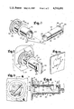
- FIG. 1 is an exploded perspective view of the pierce turn tap of the present invention and with the parts separated for clarity of illustration,
- FIG. 2 is a perspective view showing the parts assembled.
- FIG. 3 is a front elevational view showing the device in piercing position.
- FIG. 4 is a sectional view taken along line 4--4 of FIG. 3.
- FIG. 5 is a side elevational view showing the tap in open position.
- FIG. 6 is an end elevational view showing the tap in open position.
- FIG. 7 is a sectional view taken on the line 7--7 of FIG. 6.
- FIGS. 8 and 9 are end elevational views showing the tap in closed position.
- FIG. 10 is a fragmentary perspective view of the knocked out hole with the tabs remaining on the wall of the cardboard box 11.
- the numeral 20 indicates the pierce turn tap of the present invention which is adapted to be attached to a pouch or package 21 containing fluidic material to be dispensed.
- the tap 20 includes or consists of two pieces, namely an outer body member 22, and an inner piercing member 23.
- the outer body member 22 includes a cylindrical sleeve 24, FIG. 1; and a flange 25 is arranged on the inner end of the sleeve 24.
- the flange 25 is adapted to be secured to the outer surface of the pouch 21 in a suitable manner as for example by means of ultrasonic welding, adhesives, other joining techniques or the like.
- Curved rim portions 26 are provided on the outer surface of the sleeve 24, and the rim portions 26 are spaced from flange 25 whereby there is defined a space 27 for receiving a portion of a cardboard box, container or the like, therein, as for example when the unit is being used in a bag and box construction such as that shown in prior patent application Ser. No. 136,672 of William C. Christine, filed Apr. 2, 1980.
- Reinforcements 28 are provided on the outer surface of the sleeve 24 as shown in the drawing. As shown in broken lines or dotted lines in FIG.
- the numeral 7 indicates a portion of a cardboard box which has tabs 8 that fit into space 6 defined between the projections 28, and this construction provides a locking means because the tabs 8 of the cardbord box 7 are arranged so that the body of the tap is locked and cannot rotate when the tap is rotated in use.
- a knocked out hole 4 with the tabs 8 remaining and the tabs 8 are adapted to be folded up along the dotted lines 3 for insertion of the tap and then folded down to lock between portions 28.
- annular flange portion 29 which provides a convenient hand grip to facilitate the manual operation or manipulation of of the tap.
- the sleeve 24 further has a discharge opening 30 therein which is adapted to have fluidic material 31 selectively dispensed or discharged therethrough, FIG. 5, when the parts are properly positioned or arranged relative to each other.
- the outer end of sleeve 24 is open as in 32, and arranged on the outer end portion of the sleeve 24 is a curved stop element 33 for a purpose to be later described.
- a shoulder 34 is provided on the sleeve 24 adjacent to the outer end.
- the inner piercing member 23 includes a cylindrical element 35 that has a handle 36 on its outer end, and indicia in the form of an arrow 37 is provided on a convenient outer portion of the handle 36.
- a stop piece 38 which is adapted to selectively co-act with the stop element 33 as later described in this application. Certain aspects of the attachment of the tap to the pouch are shown and described in prior patent application, Ser. No. 124,971 of William C. Christine.
- annular or circular groove 39 which has a unique configuration so that it includes a flat wall section 40 as well as an inclined wall section or surface 41, FIG. 7.
- An inwardly disposed rib or keeper 42 is formed on the inner surface of the sleeve 24 so that the keeper 42 can selectively engage the groove 39 in a locking relationship.
- the cylindrical section 35 of the piercer 23 is adapted to be made of a relatively soft plastic material.
- a pointed, sharp piercer 43 which is adapted to selectively form an opening 44 in the pouch 21, and by properly moving the piercer inward and rotating the same, a flap portion 45 will be provided on the pouch, FIG. 5.
- a soft lip 46 there is provided on the inner piercing member 23 a soft lip 46, FIG. 4.
- the inner piercing member 23 has an opening 47 therein that is mounted for movement into and out of registry with the opening 30 in the sleeve 24. The inner end of the piercing member 23 is opened as at 48.
- the tap 20 of the present invention is adapted to be suitably secured to a pouch 21 in any suitable manner, as for example the flange 25 can be ultrasonically bonded or adhesively secured or otherwise joined to the outer surface of the pouch 21.
- the tap can be used in conjunction with a bag-in-box construction or it may be used in other types of operations.
- the tap 20 further includes the inner piercing member 23 which is telescopically mounted within the outer member 22.
- the piercing member 23 is in the outer position, and when it is desired to dispense the quantity of the fluidic material from the pouch 21, it is only necessary to manually push the piercing member 23 inwardly and rotate the same whereby the sharp piercing element 43 will cut an opening 44 in the pouch 21 so as to leave a flap portion 45 attached to the pouch.
- the fluidic material can flow through the opening 44, then through the hollow interior of the member 23, and out through the registering openings 30 and 47 so that, for example, as shown in FIG. 4, the fluidic material 31 can be disposed into a receptacle or the like.
- the member 23 can be selectively rotated to move the opening 47 out of registry with the opening 30 so that no further dispensing or discharge of material will occur.
- outer member 22 is provided with the inwardly disposed annular keeper or rib 42 which selectively engages the annular slot or groove 39 so as to retain the parts in piercing position as shown in FIG. 4.
- the parts can be made of any suitable material and in different shapes or sizes as desired or required.
- the tap of the present invention is adapted to be used with pouches containing various types of material such as wine, juice, oil, water, or other materials exhibiting fluidic characteristics, and the like.
- Some of the important aspects or features of the present invention are as follows: There is provided a tap that is adapted to be automatically attached in a form/fill/seal pouch machine.
- the tap body is cylindrical so that the sleeve of the attachment system can come down around the tap and apply pressure to the attachment flange.
- the tap consists of an inner member 23 with a piercer 43, the inner member being fitted within the body member 22 and wherein the inner member is restrained in a parked position by the keeper 42 that is disposed inwardly on the sleeve 24.
- the annular groove 39 which has a unique configuration so that it includes the flat surface or shoulder 40 as well as the inclined surface 41, and as shown in FIG. 7, the keeper 42 when engaging the groove 39 will maintain the parts in an open locked position.
- the piercer can be actuated easily by pushing the inner member 23 forward so that the piercing element 43 pierces the film 21 to provide the opening 44 and leave the flap portion 45 partially connected to the remaining portion of the pouch.
- the piercing element 43 cuts away the film to present or provide a large unrestricted opening 44.
- the pierce turn tap of the present invention is of a two piece construction with an integral seal ring molded into one of the two parts so that there is created a seal between the parts and this prevents leakage.
- valves As is known, in the past, two piece one-quarter turn cocks or valves have been made for many years and sealed face to face by tapered fits. For example, many years ago valves with cylindrical parts were provided using an "O" ring seal around the circumference of the port.
- the problem is to prevent leakage while still having minimum friction between the two parts. Friction makes the tap difficult to turn and also difficult to mount properly on the pouch or to fasten on to the box. Thus, if the friction is too great, the body of the tap tends to want to rotate with the inner portion and tends to tear the tap off the pouch and tear it out of the box on which it is mounted.
- the present invention solves this problem by creating a tap with a slip fit between the two parts for ease of operation, and there is provided a raised seal area around the circumference of the port, and this eliminates the leakage and creates only minimum friction.
- the pierce turn tap consists of only two pieces so that it can be made at low cost, the pierce feature, and the integral molded seat means.
- the pierce turn tap of the present invention is adapted to be molded at low cost and attached at high speed, and hence at low cost.
- the pierce turn tap is capable of high flow because the pouch is not only pierced, but cut out leaving a large opening in the flap of material that cannot pass through the valve.
- a cylindrical tap and film piercer which functions as a valve and wherein the inner and outer member interfit and telescope so that the package film can be severed.
- the keeper 42 will either selectively engage the groove 39 to retain the parts in a locked position, or the keeper 42 can dig into the soft plastic member 35 in a different position to temporarily hold the parts in the outer position until the film is to be pierced.
- the handle 36 can be manually gripped so that the piercing member can be rotated to move the opening 37 out of registry or alignment with the opening 30 so that no further material will be dispensed.
- the stop element 38 co-acts with the arcuate stop element 33 to limit rotation of the piercing element 23 within the outer body member 22.
- a two piece pierce turn tap which can be arranged in either a pre-piercing state, or wherein the parts can be arranged in a post-piercing state or position. Further, when the device is in the ultimate post-piercing position, it is unable to return to a pre-piercing position due to the inter-engagement of the keeper 42 and groove 39. However, even though the parts are in a post-piercing position, the inner member 23 can rotate about a 240° circumference from a closed to an open position, and vice versa so that fluid contents from the film package or pouch can be dispensed.
- the tap is constructed so that the parts will be restrained in a "parked" position until it is desired that the piercer is needed and it is desired to pierce the film package, and yet accidental piercing will be prevented, although the device can be easily actuated by pushing the inner member forward so that the element 43 cuts through the film. After the piercing element has been pushed forward and rotated approximately 240° C., the piercer cuts away the film to present a generally large unrestricted opening therein so that the fluidic contents can be dispensed. Then, the tap is restrained from returning from its post-piercing position to its pre-piercing position.
- a two piece tap with an integral seal ring molded into one of the two parts creating a seal between the parts so as to prevent leakage and concurrently therewith performing the restraining means which precludes the return of the tap from the post-piercing position to the pre-piercing position or "parked" position.
- the handle 36 provides a convenient grasping element to permit convenient inward movement of the piercing element 23 and also the handle 36 facilitates rotation of the piercing element 23.
- the handle 36 can function in conjunction with the flange 29 to provide a convenient grip.
- a portion of a cardboard box can be conveniently received in the space 27 between the flanges 26 and 25.
- the portions 28 provide reinforcement for the tap, especially in the vicinity of the area where the keeper or lug 42 projects inwardly.
- the lug or keeper 42 can selectively engage thr groove 39 to prevent accidentally movement of the parts from their desired position. Otherwise, the lug 42 can frictionally engage the soft outer surface of the portion 35 so that friction is provided to retain the piercer from improperly extending the piercer into the film pouch until the desired time.
- a slip fit relationship is provided between the outer surface of the member 23 and the inner surface of the member 22, as shown in FIG. 7, the groove 39 has a triangular shape in cross section so that it includes the surfaces 40 and 41. This construction provides a safe locking arrangement when the groove 39 is engaged by the keeper or lug 42.
- the handle 36 can be used for rotating the inner member either left or right through approximately 240° to achieve the desired results. Even though the inner member can rotate within the outer member, there is a generally tight fit between the surfaces of these members, and this in conjunction with the raised seal construction assures that there will be no fluid passage from the pouch until the handle 36 turns the piercer through an arc and thus, no fluid can be dispensed until the arrow 37 points downwardly as shown in FIG. 6. Thus, by turning the handle 36 so that the arrow 37 moves to either a position shown in FIG. 8 or FIG. 9, the device is in closed position so that no fluidic material will be dispensed therefrom.
- FIG. 6 illustrates the device in open position.
- FIG. 8 illustrates the device rotated approximately 135° to the right to closed position from opened position.
- FIG. 9 illustrates the device rotated to the left approximately 135° to closed position from opened.
- FIG. 3 indicates the direction of rotation.
- FIG. 5 shows the tap in locked open position with the openings 30 and 47 in alignment or registry.
- FIG. 4 shows the device in parked position. To pierce, with the parts arranged as shown in FIG. 4, it is only necessary to push down on the wedge and then rotate 240° from stop to stop, such as from the stop 38 to either edge of the stop 33.
- the pouch is indicated by the numeral 21, and as previously stated, the pouch may have any type of material to be dispensed of a fluidic nature.
- the parts are in an outer position such as that shown in FIG. 4, and the interrelationship and inter-engagement of the parts prevents accidental piercing of the film.
- the sequence of operations previously described is carried out so that the film is pierced an the fluidic material can be dispensed.
- the inner member can be rotated to either an opened or closed position to selectively permit material to be discharged into a waiting receptacle or the like.
- a pierce turn tap that includes an integral seat (seal) means and wherein the two piece tap is of economical construction.
- the tap can be conveniently made of plastic and the plastic turn tap has an integral flange for sealing directly to a plastic pouch.
- the plastic turn tap has external cylindrical configuration suitable for holding in an automatic attachment system for the purpose of sealing directly on a plastic pouch.
- the two piece turn tap has molded integral seals, and is adapted to be molded of heat sealable resins and formed with an integral flange for the purpose of attaching directly to a plastic pouch and the tap is adapted to be formed with external concentric body flanges to permit alignment and automatic attachment.
- the plastic tap has the lock means to receive tabs 8 of the cardboard box 7, and the tabs 8 are adapted to be received in the space 6 between projections 28 so that the body of the tap is locked and cannot rotate when the tap is rotated in use.
- the space 27 provides a space for receiving a portion of the cardboard box 7.
- An important aspect of the present invention is the sealing means in conjunction with other features such as the tap made of two parts, the construction that permits use with an automatic attachment system for facilitating the sealing of the tap directly on a plastic pouch, the locking feature, and the economical construction that is provided by means of the two-part construction as well as the efficiency of operation that is provided by means of the tap.
- the lip 46 is of generally soft material and squeezes down on the edge 2 at the proper time, and this construction assures there will be no leakage of fluid between the portions 46 and 2.
- FIG. 10 illustrates the configuration of the tabs in the drawings.
Abstract
Description
Claims (7)
Priority Applications (1)
| Application Number | Priority Date | Filing Date | Title |
|---|---|---|---|
| US06/342,660 US4516691A (en) | 1982-01-25 | 1982-01-25 | Pierce turn tap |
Applications Claiming Priority (1)
| Application Number | Priority Date | Filing Date | Title |
|---|---|---|---|
| US06/342,660 US4516691A (en) | 1982-01-25 | 1982-01-25 | Pierce turn tap |
Publications (1)
| Publication Number | Publication Date |
|---|---|
| US4516691A true US4516691A (en) | 1985-05-14 |
Family
ID=23342740
Family Applications (1)
| Application Number | Title | Priority Date | Filing Date |
|---|---|---|---|
| US06/342,660 Expired - Lifetime US4516691A (en) | 1982-01-25 | 1982-01-25 | Pierce turn tap |
Country Status (1)
| Country | Link |
|---|---|
| US (1) | US4516691A (en) |
Cited By (36)
| Publication number | Priority date | Publication date | Assignee | Title |
|---|---|---|---|---|
| US4583650A (en) * | 1983-08-17 | 1986-04-22 | Proprietary Technology | Manually releasable drainport closure apparatus |
| US5016757A (en) * | 1988-06-22 | 1991-05-21 | Societe Generele Des Eaux Minerals De Vittel | Opening-closing device for a bag of flexible synthetic material with limited penetration |
| US5337775A (en) * | 1992-01-30 | 1994-08-16 | Waddington & Duval Limited | Dispensing taps |
| US5630529A (en) * | 1995-06-26 | 1997-05-20 | Chlupp; Christopher F. | Piercing tap and method of use therefor |
| US5845812A (en) * | 1996-01-31 | 1998-12-08 | The Testor Corporation | Paint pouch fitting |
| US6283331B1 (en) * | 2000-04-21 | 2001-09-04 | Nathaniel Lucas | Contact opening cap for bottles |
| GB2361519A (en) * | 2000-04-12 | 2001-10-24 | Liquibox Corp | Dispensing tap |
| US6378730B1 (en) | 2000-10-27 | 2002-04-30 | Nestec S.A. | Quick-locking device for effecting hygienic transfer of flowable material from a container by piercing |
| US6401989B1 (en) * | 1998-08-06 | 2002-06-11 | Guenter Grittmann | Stowable spigot |
| WO2002049956A2 (en) * | 2000-12-18 | 2002-06-27 | Colder Products Company | Dispensing valve assembly for liquid |
| US6772910B1 (en) * | 1999-11-17 | 2004-08-10 | Fredrick Michael Coory | Piercing cap for a container |
| US20080029540A1 (en) * | 2006-07-31 | 2008-02-07 | Johnson James W | Piercing fitment assembly |
| US20080083788A1 (en) * | 2006-09-08 | 2008-04-10 | Daniel Py | Apparatus for sealing and engaging sterile chambers |
| US20080197145A1 (en) * | 2000-10-23 | 2008-08-21 | Daniel Py | Method for Dispensing Ophthalmic Fluid |
| US20100140290A1 (en) * | 2002-08-13 | 2010-06-10 | Daniel Py | Container and Valve Assembly for Storing and Dispensing Substances, and Related Method |
| US20100200613A1 (en) * | 2009-02-11 | 2010-08-12 | Ds Smith Plastics Limited | Disposable assembly for a reusable urn or vessel |
| US20110146205A1 (en) * | 2009-12-22 | 2011-06-23 | Caudle Timothy G | Aseptic Packaging system, packaging process and package with internal fitment |
| US20110146204A1 (en) * | 2009-12-22 | 2011-06-23 | Caudle Timothy G | Aseptic packaging system, packaging process and package with external fitment |
| US20110226809A1 (en) * | 2010-03-22 | 2011-09-22 | Malo Michel | Pouring device |
| US20120074343A1 (en) * | 2009-06-12 | 2012-03-29 | Christiaan Johannes Meintjes | tap |
| CH705673A1 (en) * | 2011-10-28 | 2013-04-30 | Codefine Sa | drain valves stabilizing device and / or filling a flexible container for transporting liquids or powdery materials. |
| US20140261854A1 (en) * | 2013-03-13 | 2014-09-18 | Illinois Tool Works, Inc. | Bag in box dispensing container |
| US20150359379A1 (en) * | 2013-11-05 | 2015-12-17 | Plascon Group | Selectively sealable liner for a vessel |
| US20160229602A1 (en) * | 2015-02-06 | 2016-08-11 | Process4, Inc. | Closeable Container Cap |
| US9440773B2 (en) | 2003-07-17 | 2016-09-13 | Medinstill Development Llc | Device with one-way valve |
| US9630755B2 (en) | 2001-10-16 | 2017-04-25 | Medinstill Development Llc | Dispenser and method for storing and dispensing sterile product |
| US9725228B2 (en) | 2000-10-23 | 2017-08-08 | Dr. Py Institute Llc | Fluid dispenser having a one-way valve, pump, variable-volume storage chamber, and a needle penetrable and laser resealable portion |
| US9963288B2 (en) | 2003-05-12 | 2018-05-08 | Maej Llc | Dispenser and apparatus and method for filling a dispenser |
| US10051990B2 (en) | 2013-11-05 | 2018-08-21 | Plascon Group | Liner for a vessel |
| US10112820B1 (en) | 2016-01-19 | 2018-10-30 | Dss Rapak, Inc. | Beverage dispensing system with disposable liner and faucet |
| US10160583B2 (en) | 2015-05-27 | 2018-12-25 | Ds Smith Plastics Limited | Co-injection molded dispensing components |
| US10227227B2 (en) | 2013-11-05 | 2019-03-12 | Plascon Group | Liner for a vessel |
| US20190359472A1 (en) * | 2018-05-28 | 2019-11-28 | Biab Holdings Inc. | Food grade disposable container with a one ounce (1 oz.) or one-and-a-half ounce (1.5 oz.) tap for pouring alcohol with a countertop dispensing stand device, system, and method |
| US20220306445A1 (en) * | 2021-03-26 | 2022-09-29 | Henkel IP & Holding GmbH | Dispensing system for dispensing a liquid from a replacement container |
| US20220324693A1 (en) * | 2019-09-04 | 2022-10-13 | Oam Gmbh | Tap and container or beer keg having a tap |
| US20230348257A1 (en) * | 2020-07-31 | 2023-11-02 | Itap International S.R.L. | Dispensing device for containers, preferably flexible containers for liquids, and assembly comprising a container and said device |
Citations (9)
| Publication number | Priority date | Publication date | Assignee | Title |
|---|---|---|---|---|
| US594258A (en) * | 1897-11-23 | lines | ||
| US2698113A (en) * | 1953-04-10 | 1954-12-28 | Linton Merwyn Bradley | Dispensing bottle cap device |
| US3062411A (en) * | 1959-05-29 | 1962-11-06 | Colgate Pahnolive Company | Dispensing valve actuator |
| US3223117A (en) * | 1964-03-04 | 1965-12-14 | Corrugated Container Company | Dispensing valve |
| US4214675A (en) * | 1978-02-27 | 1980-07-29 | Schmit Justin M | Liquid pouch in a carton with a pouring spout |
| CH621985A5 (en) * | 1977-12-29 | 1981-03-13 | Ernst & Co Inh Geiger & Neuens | Portion package for drainage pipe cleaning agents |
| WO1981002418A1 (en) * | 1980-02-27 | 1981-09-03 | W Christine | Combined piercer and valve for flexible bag |
| GB2082152A (en) * | 1980-06-24 | 1982-03-03 | A C I Operations | Tap assembly for a container |
| US4322018A (en) * | 1980-04-17 | 1982-03-30 | Rutter Christopher C | Fluid dispenser |
-
1982
- 1982-01-25 US US06/342,660 patent/US4516691A/en not_active Expired - Lifetime
Patent Citations (9)
| Publication number | Priority date | Publication date | Assignee | Title |
|---|---|---|---|---|
| US594258A (en) * | 1897-11-23 | lines | ||
| US2698113A (en) * | 1953-04-10 | 1954-12-28 | Linton Merwyn Bradley | Dispensing bottle cap device |
| US3062411A (en) * | 1959-05-29 | 1962-11-06 | Colgate Pahnolive Company | Dispensing valve actuator |
| US3223117A (en) * | 1964-03-04 | 1965-12-14 | Corrugated Container Company | Dispensing valve |
| CH621985A5 (en) * | 1977-12-29 | 1981-03-13 | Ernst & Co Inh Geiger & Neuens | Portion package for drainage pipe cleaning agents |
| US4214675A (en) * | 1978-02-27 | 1980-07-29 | Schmit Justin M | Liquid pouch in a carton with a pouring spout |
| WO1981002418A1 (en) * | 1980-02-27 | 1981-09-03 | W Christine | Combined piercer and valve for flexible bag |
| US4322018A (en) * | 1980-04-17 | 1982-03-30 | Rutter Christopher C | Fluid dispenser |
| GB2082152A (en) * | 1980-06-24 | 1982-03-03 | A C I Operations | Tap assembly for a container |
Cited By (59)
| Publication number | Priority date | Publication date | Assignee | Title |
|---|---|---|---|---|
| US4583650A (en) * | 1983-08-17 | 1986-04-22 | Proprietary Technology | Manually releasable drainport closure apparatus |
| US5016757A (en) * | 1988-06-22 | 1991-05-21 | Societe Generele Des Eaux Minerals De Vittel | Opening-closing device for a bag of flexible synthetic material with limited penetration |
| US5337775A (en) * | 1992-01-30 | 1994-08-16 | Waddington & Duval Limited | Dispensing taps |
| US5630529A (en) * | 1995-06-26 | 1997-05-20 | Chlupp; Christopher F. | Piercing tap and method of use therefor |
| US5845812A (en) * | 1996-01-31 | 1998-12-08 | The Testor Corporation | Paint pouch fitting |
| US6401989B1 (en) * | 1998-08-06 | 2002-06-11 | Guenter Grittmann | Stowable spigot |
| US6772910B1 (en) * | 1999-11-17 | 2004-08-10 | Fredrick Michael Coory | Piercing cap for a container |
| GB2361519A (en) * | 2000-04-12 | 2001-10-24 | Liquibox Corp | Dispensing tap |
| US6283331B1 (en) * | 2000-04-21 | 2001-09-04 | Nathaniel Lucas | Contact opening cap for bottles |
| US9725228B2 (en) | 2000-10-23 | 2017-08-08 | Dr. Py Institute Llc | Fluid dispenser having a one-way valve, pump, variable-volume storage chamber, and a needle penetrable and laser resealable portion |
| US20080197145A1 (en) * | 2000-10-23 | 2008-08-21 | Daniel Py | Method for Dispensing Ophthalmic Fluid |
| US9668914B2 (en) | 2000-10-23 | 2017-06-06 | Dr. Py Institute Llc | Method for dispensing ophthalmic fluid |
| US8757436B2 (en) | 2000-10-23 | 2014-06-24 | Medical Instill Technologies, Inc. | Method for dispensing ophthalmic fluid |
| US6378730B1 (en) | 2000-10-27 | 2002-04-30 | Nestec S.A. | Quick-locking device for effecting hygienic transfer of flowable material from a container by piercing |
| WO2002049956A3 (en) * | 2000-12-18 | 2003-09-12 | Colder Prod Co | Dispensing valve assembly for liquid |
| WO2002049956A2 (en) * | 2000-12-18 | 2002-06-27 | Colder Products Company | Dispensing valve assembly for liquid |
| US6848602B2 (en) | 2000-12-18 | 2005-02-01 | Colder Products Company | Coupling and closure apparatus for dispensing valve assembly |
| US20050127117A1 (en) * | 2000-12-18 | 2005-06-16 | Colder Products Company | Coupling enclosure apparatus for dispensing valve assembly |
| US9630755B2 (en) | 2001-10-16 | 2017-04-25 | Medinstill Development Llc | Dispenser and method for storing and dispensing sterile product |
| US8672195B2 (en) | 2002-08-13 | 2014-03-18 | Medical Instill Technologies, Inc. | Device with chamber and first and second valves in communication therewith, and related method |
| US20100140290A1 (en) * | 2002-08-13 | 2010-06-10 | Daniel Py | Container and Valve Assembly for Storing and Dispensing Substances, and Related Method |
| US9408455B2 (en) | 2002-08-13 | 2016-08-09 | MedInstill Development, LLC | Container and valve assembly for storing and dispensing substances, and related method |
| US9963288B2 (en) | 2003-05-12 | 2018-05-08 | Maej Llc | Dispenser and apparatus and method for filling a dispenser |
| US9440773B2 (en) | 2003-07-17 | 2016-09-13 | Medinstill Development Llc | Device with one-way valve |
| US7980424B2 (en) * | 2006-07-31 | 2011-07-19 | Liqui-Box Corporation | Piercing fitment assembly |
| US20080029540A1 (en) * | 2006-07-31 | 2008-02-07 | Johnson James W | Piercing fitment assembly |
| US20080083788A1 (en) * | 2006-09-08 | 2008-04-10 | Daniel Py | Apparatus for sealing and engaging sterile chambers |
| US10508014B2 (en) | 2009-02-11 | 2019-12-17 | Ds Smith Plastics Limited | Disposable assembly for a reusable urn or vessel |
| US10773945B2 (en) | 2009-02-11 | 2020-09-15 | Corplex Plastics Uk Ltd. | Disposable assembly for a reusable urn or vessel |
| US8757441B2 (en) * | 2009-02-11 | 2014-06-24 | Ds Smith Plastics Limited | Disposable assembly for a reusable urn or vessel |
| US8752734B2 (en) * | 2009-02-11 | 2014-06-17 | Ds Smith Plastics Limited | Disposable assembly for a reusable urn or vessel |
| US20100200613A1 (en) * | 2009-02-11 | 2010-08-12 | Ds Smith Plastics Limited | Disposable assembly for a reusable urn or vessel |
| US9643833B2 (en) | 2009-02-11 | 2017-05-09 | Ds Smith Plastics Limited | Disposable assembly for a reusable urn or vessel |
| US20120074343A1 (en) * | 2009-06-12 | 2012-03-29 | Christiaan Johannes Meintjes | tap |
| US8375686B2 (en) | 2009-12-22 | 2013-02-19 | Cryovac, Inc. | Aseptic packaging system, packaging process and package with external fitment |
| US8387348B2 (en) | 2009-12-22 | 2013-03-05 | Cryovac, Inc. | Aseptic packaging system, packaging process and package with internal fitment |
| US20110146204A1 (en) * | 2009-12-22 | 2011-06-23 | Caudle Timothy G | Aseptic packaging system, packaging process and package with external fitment |
| US20110146205A1 (en) * | 2009-12-22 | 2011-06-23 | Caudle Timothy G | Aseptic Packaging system, packaging process and package with internal fitment |
| US20110226809A1 (en) * | 2010-03-22 | 2011-09-22 | Malo Michel | Pouring device |
| CH705673A1 (en) * | 2011-10-28 | 2013-04-30 | Codefine Sa | drain valves stabilizing device and / or filling a flexible container for transporting liquids or powdery materials. |
| CN103958367B (en) * | 2011-10-28 | 2016-06-01 | 科迪芬公司 | For stable flexible cell outlet valve and/or filling-valve to carry the device of liquid or pulverulent material |
| CN103958367A (en) * | 2011-10-28 | 2014-07-30 | 科迪芬公司 | Device for the stabilisation of drain and/or fill valves for a flexible container intended for the transportation of liquids or pulverulent materials |
| US20140261854A1 (en) * | 2013-03-13 | 2014-09-18 | Illinois Tool Works, Inc. | Bag in box dispensing container |
| US20150359379A1 (en) * | 2013-11-05 | 2015-12-17 | Plascon Group | Selectively sealable liner for a vessel |
| US10472225B2 (en) | 2013-11-05 | 2019-11-12 | Plascon Packaging, Inc. | Liner |
| US10051990B2 (en) | 2013-11-05 | 2018-08-21 | Plascon Group | Liner for a vessel |
| US10561272B2 (en) * | 2013-11-05 | 2020-02-18 | Plascon Packaging, Inc. | Selectively sealable liner for a vessel |
| US10227227B2 (en) | 2013-11-05 | 2019-03-12 | Plascon Group | Liner for a vessel |
| US9807976B2 (en) * | 2015-02-06 | 2017-11-07 | Process4, Inc. | Closeable container cap |
| US20160229602A1 (en) * | 2015-02-06 | 2016-08-11 | Process4, Inc. | Closeable Container Cap |
| US10160583B2 (en) | 2015-05-27 | 2018-12-25 | Ds Smith Plastics Limited | Co-injection molded dispensing components |
| US10875694B2 (en) | 2015-05-27 | 2020-12-29 | Corplex Plastics Uk Ltd. | Co-injection molded dispensing components method |
| US10112820B1 (en) | 2016-01-19 | 2018-10-30 | Dss Rapak, Inc. | Beverage dispensing system with disposable liner and faucet |
| US20190359472A1 (en) * | 2018-05-28 | 2019-11-28 | Biab Holdings Inc. | Food grade disposable container with a one ounce (1 oz.) or one-and-a-half ounce (1.5 oz.) tap for pouring alcohol with a countertop dispensing stand device, system, and method |
| US20220324693A1 (en) * | 2019-09-04 | 2022-10-13 | Oam Gmbh | Tap and container or beer keg having a tap |
| US20230348257A1 (en) * | 2020-07-31 | 2023-11-02 | Itap International S.R.L. | Dispensing device for containers, preferably flexible containers for liquids, and assembly comprising a container and said device |
| US20220306445A1 (en) * | 2021-03-26 | 2022-09-29 | Henkel IP & Holding GmbH | Dispensing system for dispensing a liquid from a replacement container |
| US11667512B2 (en) * | 2021-03-26 | 2023-06-06 | Henkel Ag & Co. Kgaa | Dispensing system for dispensing a liquid from a replacement container |
| US11827509B2 (en) | 2021-03-26 | 2023-11-28 | Henkel Ag & Co. Kgaa | Dispensing system for dispensing a liquid from a replacement container |
Similar Documents
| Publication | Publication Date | Title |
|---|---|---|
| US4516691A (en) | Pierce turn tap | |
| US4440316A (en) | Combined piercer and valve for flexible bag | |
| CA1158615A (en) | Apparatus for dispensing liquids | |
| US4475670A (en) | Fluid dispenser | |
| US4493438A (en) | Fluid dispenser | |
| US4416395A (en) | Bulk liquid container, tap and tap assembly therefore | |
| US5497909A (en) | Reuseable pouch fitment | |
| US4600127A (en) | Dispensing taps | |
| JP5655008B2 (en) | Duckbill type flip cap fitting for foldable containers | |
| US6378730B1 (en) | Quick-locking device for effecting hygienic transfer of flowable material from a container by piercing | |
| US5141134A (en) | Pitcher with spout | |
| EP2385919B1 (en) | Poppet seal fitment for a collapsible bag | |
| EP0046754B1 (en) | Combined piercer and valve for flexible bag | |
| EP1129016B1 (en) | Closure device for a membrane sealed container | |
| EP0170660A1 (en) | Liquid dispensing assembly | |
| EP0026055B1 (en) | Filling-dispensing neck and closure member combination for a bag-like container | |
| US20230182976A1 (en) | Piercing cap and piercer | |
| EP2249763B1 (en) | Delivery device | |
| GB2183617A (en) | Plug for bag-in-box container | |
| US11713158B2 (en) | Reusable pour spout system and method | |
| GB2156949A (en) | Combined piercer and valve for flexible bag | |
| US20230086837A1 (en) | Pour spout system and method including reinforcing materials and auxiliary devices | |
| EP0043236A1 (en) | Container constructions | |
| JPH0618121Y2 (en) | connector | |
| NZ212004A (en) | Valve for"bag-in-box"container,incorporating initial piercing device |
Legal Events
| Date | Code | Title | Description |
|---|---|---|---|
| AS | Assignment |
Owner name: TRINITY ASSOCIATES; 533 SOUTH MAIN ST., POST OFFIC Free format text: ASSIGNMENT OF ASSIGNORS INTEREST.;ASSIGNORS:CHRISTINE, WILLIAM C.;TRILLICH, CHARLES H.;REEL/FRAME:004025/0814 Effective date: 19820809 |
|
| AS | Assignment |
Owner name: TRINITY FOUNDATION, 533 SOUTH MAIN STREET, P.O. BO Free format text: ASSIGNMENT OF ASSIGNORS INTEREST.;ASSIGNOR:TRINITY ASSOCIATES;REEL/FRAME:004357/0889 Effective date: 19850124 |
|
| STCF | Information on status: patent grant |
Free format text: PATENTED CASE |
|
| AS | Assignment |
Owner name: TRINITY FOUNDATION, 533 SOUTH MAIN STREET, P.O. BO Free format text: RERECORD OF ASSIGNMENT RECORDED REEL 4357 FRAME 889 TO CORRECT NUMBER;ASSIGNOR:TRINITY ASSOCIATES;REEL/FRAME:004391/0173 Effective date: 19850124 |
|
| FEPP | Fee payment procedure |
Free format text: PAYOR NUMBER ASSIGNED (ORIGINAL EVENT CODE: ASPN); ENTITY STATUS OF PATENT OWNER: LARGE ENTITY |
|
| FPAY | Fee payment |
Year of fee payment: 4 |
|
| AS | Assignment |
Owner name: TRIPARTE, LTD., A PA CORP., PENNSYLVANIA Free format text: ASSIGNMENT OF ASSIGNORS INTEREST.;ASSIGNOR:TRINITY FOUNDATION (A PARTNERSHIP);REEL/FRAME:005562/0203 Effective date: 19901217 |
|
| AS | Assignment |
Owner name: LIQUI-BOX ACQUISITION CORPORATION, 6950 WORTHINGTO Free format text: ASSIGNMENT OF ASSIGNORS INTEREST.;ASSIGNOR:TRI PARTE LIMITED;REEL/FRAME:005634/0036 Effective date: 19910204 Owner name: TRIPARTE, LTD., A PA CORP., PENNSYLVANIA Free format text: NUNC PRO TUNC ASSIGNMENT;ASSIGNOR:TRINITY FOUNDATION;REEL/FRAME:005600/0947 Effective date: 19910204 |
|
| FEPP | Fee payment procedure |
Free format text: PAYER NUMBER DE-ASSIGNED (ORIGINAL EVENT CODE: RMPN); ENTITY STATUS OF PATENT OWNER: LARGE ENTITY Free format text: PAYOR NUMBER ASSIGNED (ORIGINAL EVENT CODE: ASPN); ENTITY STATUS OF PATENT OWNER: LARGE ENTITY Free format text: PAT HLDR NO LONGER CLAIMS SMALL ENT STAT AS INDIV INVENTOR (ORIGINAL EVENT CODE: LSM1); ENTITY STATUS OF PATENT OWNER: LARGE ENTITY |
|
| FPAY | Fee payment |
Year of fee payment: 8 |
|
| AS | Assignment |
Owner name: INPACO CORPORATION, PENNSYLVANIA Free format text: CHANGE OF NAME;ASSIGNOR:LIQUI-BOX ACQUISITION CORPORATION;REEL/FRAME:006777/0178 Effective date: 19910225 |
|
| FPAY | Fee payment |
Year of fee payment: 12 |