US4527047A - Electrically heatable backing means for mirrors - Google Patents
Electrically heatable backing means for mirrors Download PDFInfo
- Publication number
- US4527047A US4527047A US06/543,788 US54378883A US4527047A US 4527047 A US4527047 A US 4527047A US 54378883 A US54378883 A US 54378883A US 4527047 A US4527047 A US 4527047A
- Authority
- US
- United States
- Prior art keywords
- metal
- heat
- heating element
- electrical current
- strips
- Prior art date
- Legal status (The legal status is an assumption and is not a legal conclusion. Google has not performed a legal analysis and makes no representation as to the accuracy of the status listed.)
- Expired - Fee Related
Links
Images

Classifications
-
- H—ELECTRICITY
- H05—ELECTRIC TECHNIQUES NOT OTHERWISE PROVIDED FOR
- H05B—ELECTRIC HEATING; ELECTRIC LIGHT SOURCES NOT OTHERWISE PROVIDED FOR; CIRCUIT ARRANGEMENTS FOR ELECTRIC LIGHT SOURCES, IN GENERAL
- H05B3/00—Ohmic-resistance heating
- H05B3/84—Heating arrangements specially adapted for transparent or reflecting areas, e.g. for demisting or de-icing windows, mirrors or vehicle windshields
- H05B3/845—Heating arrangements specially adapted for transparent or reflecting areas, e.g. for demisting or de-icing windows, mirrors or vehicle windshields specially adapted for reflecting surfaces, e.g. bathroom - or rearview mirrors
-
- B—PERFORMING OPERATIONS; TRANSPORTING
- B60—VEHICLES IN GENERAL
- B60R—VEHICLES, VEHICLE FITTINGS, OR VEHICLE PARTS, NOT OTHERWISE PROVIDED FOR
- B60R1/00—Optical viewing arrangements; Real-time viewing arrangements for drivers or passengers using optical image capturing systems, e.g. cameras or video systems specially adapted for use in or on vehicles
- B60R1/02—Rear-view mirror arrangements
- B60R1/06—Rear-view mirror arrangements mounted on vehicle exterior
- B60R1/0602—Rear-view mirror arrangements mounted on vehicle exterior comprising means for cleaning or deicing
Definitions
- the invention relates to a multi-component electrically heatable backing means for mirrors, comprising thin metal sheet means and at least one plate-shaped electrical heating element having two main faces being connected with said metal sheet means in an electrical current- and heat-conducting manner.
- Such heatable backing means are, for instance, known from German Pat. No. 29 19 968. They serve in particular for heating the external mirrors of motor vehicles, but can also be used for other mirrors such as, for instance, bathroom mirrors.
- the metal sheet means serve for distributing over the entire surface of the mirror heat which is generated in a small surface area by the heating elements, thereby preserving the mirror at least substantially free from fogging or ice formation.
- the center of such mirror is heated first, thereby ensuring that at least a part of the mirror surface of an ice-covered mirror becomes usable already after a short heating period.
- the desired heat-distribution can be attained by a corresponding dimensioning of the thickness of the backing material as well as the width of the heatable backing means.
- Heatable backing means of the above-described kind are usually produced from thin metal sheet, for instance copper sheet or aluminum foil.
- the sheets or foils are glued on to the back of a mirror.
- Heating elements mostly used consist of small plate-shaped bodies of ceramic masses containing a resistor whose resistance increases with increasing temperature over the temperature range in question (so-called PTC elements).
- PTC elements a resistor whose resistance increases with increasing temperature over the temperature range in question
- the metal sheets or foils serve at the same time as electrical current feed-in to the heating elements, wherefor their arrangement must be such that the metal sheets or foils should cover the two main faces of a plate-shaped heating element, i.e., the two flat faces, and be in current- and heat-conducting connection therewith.
- the metal sheets are of such shape and so arranged that they overlap with formation of stripes, the heating elements being arranged between the overlapping zones of the sheets.
- the known heatable backing means for mirrors suffer from the drawback that they must be specifically cut to fit the size of the mirror. This leads to disadvantages during manufacture, when the backing means are to be applied simultaneously with the manufacture of the mirror. But there ensue even more significant drawbacks for the manufacturer and the dealer, and last not least for the user, when the heatable backings are offered in commerce as retro-fitting parts, which are to be glued by the user himself on to the back of a mirror. In this case, the maintenance of stores of a great variety is necessary in order to cover mirrors of any size likely to occur. Moreover, the user may have to acquire several sizes, if he wants to equip different mirrors with heatable backings.
- the invention aims to solve the problem of developing further and improving the known multi-component heatable backings of mirrors in such a manner as to provide heatable backing means for the equipment of mirrors of different shapes and sizes, which means comprise only a few predetermined building units.
- a multi-component electrical heating means for mirrors in which the said metal sheet means consist essentially of at least three metal strips which are spaced from one another and extend parallel with each other, the aforesaid heating element has a first one of its two main faces in electrical current- and heat-conducting contact with at least a first one of the said metal strips and is electrically and heat-insulated from the two strips next adjacent the said first metal strip, and which heating means comprise a metal bridge connecting with one another, in electrical current- and heat-conducting contact, the said two strips next adjacent said first metal strip; the other main faces of the said heating element being in electrical current- and heat-conducting contact with the said metal bridge.
- those metal strips which are directly connected with a main surface of one or several heating elements have a width at least equal with the diameter of the respective heating element.
- the invention resides in the combination of the above-described several features which must be present in common in the novel multiple component heating means.
- the heatable backing means By subdividing the heatable backing means into at least three parallel metal strips, arranged spaced from each other, as well as bridges, the backs of mirrors having different widths and shapes can be easily covered. If three strips are not sufficient to this end, a fourth or a fifth strip or several more can be added, and the necessary heating elements can be arranged in correspondence with the desired heat distribution. Instead of the mentioned metal strips, strips of other conductive materials such as metal fabric, conductive synthetic resin material and the like can be used.
- the metal strips which are in direct connection with a main face of one or several heating elements are of a width equal to the diameter of the respective heating element.
- the widths of the other metal strips can deviate from this width; e.g., they can be broader.
- the bridges will be subject to the last-mentioned rule, i.e., they will be in direct contact with one of the main faces of the heating elements, it is recommended that the breadth of the bridges corresponds approximately with the diameter of the respective heating element.
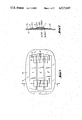
- FIG. 1 is a plan view of the back of a mirror, bearing a three-strip heatable backing means
- FIG. 2 is a cross-sectional view of the same embodiment, taken along a plane indicated by II--II in FIG. 1;
- FIG. 3 is a plan view of the back of another mirror, bearing a four-strip heatable backing means.
- the entire heatable backing means according to the invention a first embodiment of which is shown in FIGS. 1 and 2 a second embodiment of which is shown in FIG. 3, are designated by the reference numerals 1 and 10, respectively.
- these backing means consist of the three metal strips 2, 2' and 2" which are arranged spaced from, and parallel with each other, on the back wall 3a of a mirror 3.
- the backing means 1 further comprise two disc-shaped electrical heating elements 4 whose two main faces (large, flat faces) 4a and 4b are connected with different metal strips in an electric current- and heat-conducting manner.
- each heating element 4, 4' is connected by means of its main faces 4a and 4a' which latter are turned toward the back 3a of the mirror 3, with the central strip 2' in electrical current- and heat-conducting contact.
- the strips 2 and 2" which are next adjacent the central strip 2' are connected with each other by means of metal bridges 5 and 5' in an electrical current- and heat-conducting manner, and the main faces 4b and 4b' which are turned away from the back 3a of the mirror 3, are in electrical current- and heat-conducting contact with the undersides 5a and 5a' of the metal bridges 5 and 5', respectively (FIG. 2).
- the metal strips 2, 2' and 2" thus do not only serve as means for the distribution of heat, but also as the means for supplying electrical current.
- connecting posts 6 and 6' can be provided on the metal strips, so that posts 6 can, for instance, be connected with the minus pole of a motor car battery while the posts 6' can be connected to the plus pole of the same current source.
- the two heating elements 4 and 4' can thus be connected in parallel and electric current will flow through them at the same time and in the same direction.
- the backing means 10 comprise four metal strips 20, 20', 20" and 20'" and three heating elements 4, 4' and 4", as well as three bridges 5, 5' and 5".
- the bridges 5 and 5" connect the metal strips 20 and 20", and make contact on their undersides with the heating elements 4 and 4" which latter make contact with the strip 20', via their main faces turned toward the latter strip.
- the bridge 5' connects the metal strips 20' and 2'" with each other, while electric current passes from the post 6 of the strip 20'", which post is connected to the negative pole of a motor car battery, through the heating wire of the heating element 4' into the strip 20" and via the post 6' of the latter back to the plus pole of the battery.
Abstract
A multiple component electrical heating device for mirrors including at least one plate-shaped electrical heating element having two main faces being connected with two of at least three metal strips which are spaced from one another and extend parallel with each other, in an electrical current-conducting and heat-conducting manner. A first one of the two main faces of the heating element is in electrical current- and heat-conducting contact with at least a first one of the metal strips and is electrically and heat-insulated from the two strips next adjacent the first metal strip. A metal bridge connects with one another, in electrical current- and heat-conducting contact, the two metal strips next adjacent the first metal strip. The other main face of the heating element is in electrical current- and heat-conducting contact with the metal bridge.
Description
The invention relates to a multi-component electrically heatable backing means for mirrors, comprising thin metal sheet means and at least one plate-shaped electrical heating element having two main faces being connected with said metal sheet means in an electrical current- and heat-conducting manner.
Such heatable backing means are, for instance, known from German Pat. No. 29 19 968. They serve in particular for heating the external mirrors of motor vehicles, but can also be used for other mirrors such as, for instance, bathroom mirrors. The metal sheet means serve for distributing over the entire surface of the mirror heat which is generated in a small surface area by the heating elements, thereby preserving the mirror at least substantially free from fogging or ice formation.
It is particularly desirable in the case of the external mirrors of motor vehicles that the center of such mirror is heated first, thereby ensuring that at least a part of the mirror surface of an ice-covered mirror becomes usable already after a short heating period. The desired heat-distribution can be attained by a corresponding dimensioning of the thickness of the backing material as well as the width of the heatable backing means.
Heatable backing means of the above-described kind are usually produced from thin metal sheet, for instance copper sheet or aluminum foil. The sheets or foils are glued on to the back of a mirror. Heating elements mostly used consist of small plate-shaped bodies of ceramic masses containing a resistor whose resistance increases with increasing temperature over the temperature range in question (so-called PTC elements). The metal sheets or foils serve at the same time as electrical current feed-in to the heating elements, wherefor their arrangement must be such that the metal sheets or foils should cover the two main faces of a plate-shaped heating element, i.e., the two flat faces, and be in current- and heat-conducting connection therewith.
In the case of German Pat. No. 29 19 968, the metal sheets are of such shape and so arranged that they overlap with formation of stripes, the heating elements being arranged between the overlapping zones of the sheets.
The known heatable backing means for mirrors suffer from the drawback that they must be specifically cut to fit the size of the mirror. This leads to disadvantages during manufacture, when the backing means are to be applied simultaneously with the manufacture of the mirror. But there ensue even more significant drawbacks for the manufacturer and the dealer, and last not least for the user, when the heatable backings are offered in commerce as retro-fitting parts, which are to be glued by the user himself on to the back of a mirror. In this case, the maintenance of stores of a great variety is necessary in order to cover mirrors of any size likely to occur. Moreover, the user may have to acquire several sizes, if he wants to equip different mirrors with heatable backings.
The invention aims to solve the problem of developing further and improving the known multi-component heatable backings of mirrors in such a manner as to provide heatable backing means for the equipment of mirrors of different shapes and sizes, which means comprise only a few predetermined building units.
This object is attained, in accordance with the present invention, by providing a multi-component electrical heating means for mirrors, as initially described, in which the said metal sheet means consist essentially of at least three metal strips which are spaced from one another and extend parallel with each other, the aforesaid heating element has a first one of its two main faces in electrical current- and heat-conducting contact with at least a first one of the said metal strips and is electrically and heat-insulated from the two strips next adjacent the said first metal strip, and which heating means comprise a metal bridge connecting with one another, in electrical current- and heat-conducting contact, the said two strips next adjacent said first metal strip; the other main faces of the said heating element being in electrical current- and heat-conducting contact with the said metal bridge.
In a preferred embodiment of the heating means according to the invention, those metal strips which are directly connected with a main surface of one or several heating elements, have a width at least equal with the diameter of the respective heating element.
Thus, the invention resides in the combination of the above-described several features which must be present in common in the novel multiple component heating means.
By subdividing the heatable backing means into at least three parallel metal strips, arranged spaced from each other, as well as bridges, the backs of mirrors having different widths and shapes can be easily covered. If three strips are not sufficient to this end, a fourth or a fifth strip or several more can be added, and the necessary heating elements can be arranged in correspondence with the desired heat distribution. Instead of the mentioned metal strips, strips of other conductive materials such as metal fabric, conductive synthetic resin material and the like can be used.
It has been found to be advantageous, if the metal strips which are in direct connection with a main face of one or several heating elements, are of a width equal to the diameter of the respective heating element. The widths of the other metal strips can deviate from this width; e.g., they can be broader. As the bridges will be subject to the last-mentioned rule, i.e., they will be in direct contact with one of the main faces of the heating elements, it is recommended that the breadth of the bridges corresponds approximately with the diameter of the respective heating element.
The invention will be explained in more detail in the following description thereof having reference to the accompanying drawing in which
FIG. 1 is a plan view of the back of a mirror, bearing a three-strip heatable backing means;
FIG. 2 is a cross-sectional view of the same embodiment, taken along a plane indicated by II--II in FIG. 1; and
FIG. 3 is a plan view of the back of another mirror, bearing a four-strip heatable backing means.
The entire heatable backing means according to the invention, a first embodiment of which is shown in FIGS. 1 and 2 a second embodiment of which is shown in FIG. 3, are designated by the reference numerals 1 and 10, respectively. In the first embodiment, these backing means consist of the three metal strips 2, 2' and 2" which are arranged spaced from, and parallel with each other, on the back wall 3a of a mirror 3. The backing means 1 further comprise two disc-shaped electrical heating elements 4 whose two main faces (large, flat faces) 4a and 4b are connected with different metal strips in an electric current- and heat-conducting manner. Thus, each heating element 4, 4' is connected by means of its main faces 4a and 4a' which latter are turned toward the back 3a of the mirror 3, with the central strip 2' in electrical current- and heat-conducting contact.
The strips 2 and 2" which are next adjacent the central strip 2' are connected with each other by means of metal bridges 5 and 5' in an electrical current- and heat-conducting manner, and the main faces 4b and 4b' which are turned away from the back 3a of the mirror 3, are in electrical current- and heat-conducting contact with the undersides 5a and 5a' of the metal bridges 5 and 5', respectively (FIG. 2).
In the backing means according to the invention as shown in FIGS. 1 and 2, the metal strips 2, 2' and 2" thus do not only serve as means for the distribution of heat, but also as the means for supplying electrical current.
For this purpose connecting posts 6 and 6' can be provided on the metal strips, so that posts 6 can, for instance, be connected with the minus pole of a motor car battery while the posts 6' can be connected to the plus pole of the same current source. As is shown in FIG. 1, the two heating elements 4 and 4' can thus be connected in parallel and electric current will flow through them at the same time and in the same direction.
In the embodiment shown in FIG. 3, the backing means 10 comprise four metal strips 20, 20', 20" and 20'" and three heating elements 4, 4' and 4", as well as three bridges 5, 5' and 5". In this embodiment, the bridges 5 and 5" connect the metal strips 20 and 20", and make contact on their undersides with the heating elements 4 and 4" which latter make contact with the strip 20', via their main faces turned toward the latter strip.
The bridge 5', on the other hand, connects the metal strips 20' and 2'" with each other, while electric current passes from the post 6 of the strip 20'", which post is connected to the negative pole of a motor car battery, through the heating wire of the heating element 4' into the strip 20" and via the post 6' of the latter back to the plus pole of the battery.
Claims (2)
1. Multiple component electrical heating means for mirrors comprising: thin metal sheet means and at least one plate-shaped electrical heating element having two main faces being connected with the said metal sheet means in an electrical current-conducting and heat-conducting manner;
said metal sheet means consisting essentially of at least three metal strips which are spaced from one another and extend parallel with each other,
the aforesaid heating element having a first one of said two main faces in electrical current- and heat-conducting contact with at least a first one of the said metal strips and said first one of said faces being electrically and heat-insulated from the two strips next adjacent the said first metal strip, and
a metal bridge connecting with one another, in electrical current- and heat-conducting contact, the said two strips next adjacent said first metal strip;
the other main face of the said heating element being in electrical current- and heat-conducting contact with the said metal bridge.
2. The heating layer of claim 1, wherein said at least one heating element has a diameter and those metal strips being directly connected with a main surface of said at least one heating element each have a width at least equal to the diameter of the respective heating element with which that metal strip is directly connected.
Applications Claiming Priority (2)
| Application Number | Priority Date | Filing Date | Title |
|---|---|---|---|
| DE19828233516U DE8233516U1 (en) | 1982-11-30 | 1982-11-30 | ELECTRIC HEATING COVER FOR MIRROR |
| DE8233516[U] | 1982-11-30 |
Publications (1)
| Publication Number | Publication Date |
|---|---|
| US4527047A true US4527047A (en) | 1985-07-02 |
Family
ID=6746037
Family Applications (1)
| Application Number | Title | Priority Date | Filing Date |
|---|---|---|---|
| US06/543,788 Expired - Fee Related US4527047A (en) | 1982-11-30 | 1983-10-20 | Electrically heatable backing means for mirrors |
Country Status (4)
| Country | Link |
|---|---|
| US (1) | US4527047A (en) |
| EP (1) | EP0110121A1 (en) |
| JP (1) | JPS59106338A (en) |
| DE (1) | DE8233516U1 (en) |
Cited By (10)
| Publication number | Priority date | Publication date | Assignee | Title |
|---|---|---|---|---|
| US4709134A (en) * | 1984-11-02 | 1987-11-24 | Dr. Ing. H.C.F. Porsche Aktiengesellschaft | Antifogging device for a display glass of an indicating instrument |
| US5043558A (en) * | 1990-09-26 | 1991-08-27 | Weed Instrument Company, Inc. | Deicing apparatus and method utilizing heat distributing means contained within surface channels |
| GB2268916A (en) * | 1992-07-25 | 1994-01-26 | Ford Motor Co | A rear view mirror installation for motor vehicles. |
| US5446576A (en) * | 1990-11-26 | 1995-08-29 | Donnelly Corporation | Electrochromic mirror for vehicles with illumination and heating control |
| US5459533A (en) * | 1993-11-12 | 1995-10-17 | See Clear Eyewear Inc. | Defogging eye wear |
| US5945872A (en) * | 1997-11-06 | 1999-08-31 | Analog Devices, Inc. | Two-phase boosted CMOS switch drive technique and circuit |
| US6060937A (en) * | 1997-11-06 | 2000-05-09 | Analog Devices, Inc. | Two-phase bootstrapped CMOS switch drive technique and circuit |
| US20050242081A1 (en) * | 2004-03-22 | 2005-11-03 | W.E.T. Automotive Systems Ag | Heater for an automotive vehicle and method of forming same |
| US20060206177A1 (en) * | 2002-06-18 | 2006-09-14 | David Bikhovsky | Electrical heating device particularyly for heating a patient body |
| US7306283B2 (en) | 2002-11-21 | 2007-12-11 | W.E.T. Automotive Systems Ag | Heater for an automotive vehicle and method of forming same |
Families Citing this family (3)
| Publication number | Priority date | Publication date | Assignee | Title |
|---|---|---|---|---|
| DE3717574A1 (en) * | 1987-05-25 | 1988-12-15 | Ruthenberg Gmbh Waermetechnik | DEVICE FOR HEATING AREAS IN OR ON MOTOR VEHICLES, FOR EXAMPLE SEATS, WINDOWS, MIRRORS, OR THE LIKE |
| US4931627A (en) * | 1988-08-16 | 1990-06-05 | Illinois Tool Works Inc. | Positive temperature coefficient heater with distributed heating capability |
| US6891136B2 (en) | 2002-06-18 | 2005-05-10 | Http-Hypothermia Therapy Ltd. | Electrical heating device |
Citations (12)
| Publication number | Priority date | Publication date | Assignee | Title |
|---|---|---|---|---|
| US3307167A (en) * | 1963-12-06 | 1967-02-28 | Motorola Inc | Electrical control circuit including indirectly heated theremistor providing abrupt change in resistance with temperature |
| US3720807A (en) * | 1972-05-01 | 1973-03-13 | Texas Instruments Inc | Food warming apparatus |
| US3996447A (en) * | 1974-11-29 | 1976-12-07 | Texas Instruments Incorporated | PTC resistance heater |
| DE2919968A1 (en) * | 1979-05-17 | 1980-11-27 | Hohe Kg | Car side mirror electric heater - has aluminium heating foils at back of mirror interconnected by PTC resistor |
| US4237366A (en) * | 1979-03-19 | 1980-12-02 | Texas Instruments Incorporated | Heated automobile mirror |
| GB2054329A (en) * | 1979-07-11 | 1981-02-11 | Nkf Groep Bv | Heatable mirror |
| DE8034131U1 (en) * | 1980-12-22 | 1981-05-27 | Kabelwerke Reinshagen Gmbh, 5600 Wuppertal | ELECTRIC HEATING DEVICE |
| DE8125567U1 (en) * | 1981-09-02 | 1982-02-11 | Kabelwerke Reinshagen Gmbh, 5600 Wuppertal | ELECTRICALLY HEATED SHEET PLATE, IN PARTICULAR FOR MOTOR VEHICLE MIRRORS |
| DE3042419A1 (en) * | 1980-11-11 | 1982-08-05 | Fritz Eichenauer GmbH & Co KG, 6744 Kandel | Heating device for motor vehicle mirror - with PTC heating elements on rear of adhesive copper foil |
| DE8214252U1 (en) * | 1982-05-15 | 1982-09-23 | Kabelwerke Reinshagen Gmbh, 5600 Wuppertal | ELECTRICALLY HEATED SHEET PLATE, IN PARTICULAR FOR MOTOR VEHICLE MIRRORS |
| EP0073521A1 (en) * | 1981-09-02 | 1983-03-09 | Kabelwerke Reinshagen GmbH | Electric heating for a mirror of an automotive vehicle |
| US4404463A (en) * | 1980-12-22 | 1983-09-13 | Kabelwerke Reinshagen Gmbh | Electrical heating device |
Family Cites Families (1)
| Publication number | Priority date | Publication date | Assignee | Title |
|---|---|---|---|---|
| BE795169A (en) * | 1972-02-09 | 1973-08-08 | Du Pont | IRON CHLORIDE OXIDATION PROCESS |
-
1982
- 1982-11-30 DE DE19828233516U patent/DE8233516U1/en not_active Expired
-
1983
- 1983-10-20 US US06/543,788 patent/US4527047A/en not_active Expired - Fee Related
- 1983-10-25 EP EP83110632A patent/EP0110121A1/en not_active Withdrawn
- 1983-11-14 JP JP58212614A patent/JPS59106338A/en active Pending
Patent Citations (12)
| Publication number | Priority date | Publication date | Assignee | Title |
|---|---|---|---|---|
| US3307167A (en) * | 1963-12-06 | 1967-02-28 | Motorola Inc | Electrical control circuit including indirectly heated theremistor providing abrupt change in resistance with temperature |
| US3720807A (en) * | 1972-05-01 | 1973-03-13 | Texas Instruments Inc | Food warming apparatus |
| US3996447A (en) * | 1974-11-29 | 1976-12-07 | Texas Instruments Incorporated | PTC resistance heater |
| US4237366A (en) * | 1979-03-19 | 1980-12-02 | Texas Instruments Incorporated | Heated automobile mirror |
| DE2919968A1 (en) * | 1979-05-17 | 1980-11-27 | Hohe Kg | Car side mirror electric heater - has aluminium heating foils at back of mirror interconnected by PTC resistor |
| GB2054329A (en) * | 1979-07-11 | 1981-02-11 | Nkf Groep Bv | Heatable mirror |
| DE3042419A1 (en) * | 1980-11-11 | 1982-08-05 | Fritz Eichenauer GmbH & Co KG, 6744 Kandel | Heating device for motor vehicle mirror - with PTC heating elements on rear of adhesive copper foil |
| DE8034131U1 (en) * | 1980-12-22 | 1981-05-27 | Kabelwerke Reinshagen Gmbh, 5600 Wuppertal | ELECTRIC HEATING DEVICE |
| US4404463A (en) * | 1980-12-22 | 1983-09-13 | Kabelwerke Reinshagen Gmbh | Electrical heating device |
| DE8125567U1 (en) * | 1981-09-02 | 1982-02-11 | Kabelwerke Reinshagen Gmbh, 5600 Wuppertal | ELECTRICALLY HEATED SHEET PLATE, IN PARTICULAR FOR MOTOR VEHICLE MIRRORS |
| EP0073521A1 (en) * | 1981-09-02 | 1983-03-09 | Kabelwerke Reinshagen GmbH | Electric heating for a mirror of an automotive vehicle |
| DE8214252U1 (en) * | 1982-05-15 | 1982-09-23 | Kabelwerke Reinshagen Gmbh, 5600 Wuppertal | ELECTRICALLY HEATED SHEET PLATE, IN PARTICULAR FOR MOTOR VEHICLE MIRRORS |
Cited By (18)
| Publication number | Priority date | Publication date | Assignee | Title |
|---|---|---|---|---|
| US4709134A (en) * | 1984-11-02 | 1987-11-24 | Dr. Ing. H.C.F. Porsche Aktiengesellschaft | Antifogging device for a display glass of an indicating instrument |
| US5043558A (en) * | 1990-09-26 | 1991-08-27 | Weed Instrument Company, Inc. | Deicing apparatus and method utilizing heat distributing means contained within surface channels |
| US5446576A (en) * | 1990-11-26 | 1995-08-29 | Donnelly Corporation | Electrochromic mirror for vehicles with illumination and heating control |
| US5610756A (en) * | 1990-11-26 | 1997-03-11 | Donnelly Corporation | Electrochromic mirror for vehicles |
| US5808777A (en) * | 1990-11-26 | 1998-09-15 | Donnelly Corporation | Electrochromic mirror for vehicles |
| GB2268916A (en) * | 1992-07-25 | 1994-01-26 | Ford Motor Co | A rear view mirror installation for motor vehicles. |
| GB2268916B (en) * | 1992-07-25 | 1995-11-01 | Ford Motor Co | A rear-view mirror installation for motor vehicles |
| US5459533A (en) * | 1993-11-12 | 1995-10-17 | See Clear Eyewear Inc. | Defogging eye wear |
| US5945872A (en) * | 1997-11-06 | 1999-08-31 | Analog Devices, Inc. | Two-phase boosted CMOS switch drive technique and circuit |
| US6060937A (en) * | 1997-11-06 | 2000-05-09 | Analog Devices, Inc. | Two-phase bootstrapped CMOS switch drive technique and circuit |
| US6118326A (en) * | 1997-11-06 | 2000-09-12 | Analog Devices, Inc. | Two-phase bootstrapped CMOS switch drive technique and circuit |
| US20060206177A1 (en) * | 2002-06-18 | 2006-09-14 | David Bikhovsky | Electrical heating device particularyly for heating a patient body |
| US7329843B2 (en) | 2002-06-18 | 2008-02-12 | Http-Hypothermia Therapy Ltd. | Electrical heating device particularly for heating a patient body |
| US7306283B2 (en) | 2002-11-21 | 2007-12-11 | W.E.T. Automotive Systems Ag | Heater for an automotive vehicle and method of forming same |
| US20100219664A1 (en) * | 2002-11-21 | 2010-09-02 | W.E.T. Automotive Systems Ag | Heater for an automotive vehicle and method of forming same |
| US8507831B2 (en) | 2002-11-21 | 2013-08-13 | W.E.T. Automotive Systems Ag | Heater for an automotive vehicle and method of forming same |
| US20050242081A1 (en) * | 2004-03-22 | 2005-11-03 | W.E.T. Automotive Systems Ag | Heater for an automotive vehicle and method of forming same |
| US7205510B2 (en) | 2004-03-22 | 2007-04-17 | W.E.T. Automotive Systems Ltd. | Heater for an automotive vehicle and method of forming same |
Also Published As
| Publication number | Publication date |
|---|---|
| JPS59106338A (en) | 1984-06-20 |
| EP0110121A1 (en) | 1984-06-13 |
| DE8233516U1 (en) | 1983-03-24 |
Similar Documents
| Publication | Publication Date | Title |
|---|---|---|
| US4527047A (en) | Electrically heatable backing means for mirrors | |
| US3752348A (en) | Motor vehicle electrically heated windshield and backlight system | |
| US3587377A (en) | Electrically heated die-cutting apparatus | |
| US5432322A (en) | Electric heating pad | |
| US2600486A (en) | Electric heater | |
| US3440408A (en) | Laminated transparent panels incorporating heating wires | |
| KR830001551B1 (en) | Electric device | |
| US5904874A (en) | Resistance heating device for flat objects such as mirrors | |
| US5408069A (en) | Self-defogging mirror | |
| US4743741A (en) | Electrically heated, glass vision unit | |
| US4954696A (en) | Self-regulating heating article having electrodes directly connected to a PTC layer | |
| EP0356087A3 (en) | Positive temperature coefficient heater | |
| WO1984004221A1 (en) | Heating pad preferably for car seats | |
| SE8402366L (en) | LAYER SELF-CONTROL HEATING DEVICE | |
| FR2571851B1 (en) | METHOD AND ASSEMBLY FOR DETERMINING THE TEMPERATURE OF A HEATING ELECTRIC RESISTOR, ESPECIALLY IN THE DEFROSTING OF AIRCRAFT SURFACES | |
| US4213028A (en) | Electric heating device for vehicle windows | |
| US3790745A (en) | Temperature control for electrically heatable window | |
| ES8105915A1 (en) | Heating arrangement using a P.T.C. resistance. | |
| IT7983611A0 (en) | ELECTRICS OBTAINED WITH THE SAME. RESISTIVE MATERIAL AND RESISTORS | |
| US2495788A (en) | Electric heater | |
| US3636311A (en) | Heating devices for vehicle windows | |
| EP0134011A3 (en) | Floorcoverings having built-in heater | |
| US2493542A (en) | Electric heating unit | |
| JPH0282485A (en) | Flat ceramic compound element | |
| GB2257608A (en) | Resistance heating mesh bondable to car seat cover. |
Legal Events
| Date | Code | Title | Description |
|---|---|---|---|
| AS | Assignment |
Owner name: FLABEG GMBH SIEMENSSTRASSE 3, D-8510 FURTH, GERMAN Free format text: ASSIGNMENT OF ASSIGNORS INTEREST.;ASSIGNOR:SEITZ, RUDOLF;REEL/FRAME:004188/0955 Effective date: 19831010 |
|
| REMI | Maintenance fee reminder mailed | ||
| LAPS | Lapse for failure to pay maintenance fees | ||
| STCH | Information on status: patent discontinuation |
Free format text: PATENT EXPIRED DUE TO NONPAYMENT OF MAINTENANCE FEES UNDER 37 CFR 1.362 |
|
| FP | Expired due to failure to pay maintenance fee |
Effective date: 19890702 |