US4535288A - Method and system for rotary speed determination - Google Patents
Method and system for rotary speed determination Download PDFInfo
- Publication number
- US4535288A US4535288A US06/399,320 US39932082A US4535288A US 4535288 A US4535288 A US 4535288A US 39932082 A US39932082 A US 39932082A US 4535288 A US4535288 A US 4535288A
- Authority
- US
- United States
- Prior art keywords
- mov
- output
- speed
- pair
- rotational speed
- Prior art date
- Legal status (The legal status is an assumption and is not a legal conclusion. Google has not performed a legal analysis and makes no representation as to the accuracy of the status listed.)
- Expired - Fee Related
Links
Images


Classifications
-
- G—PHYSICS
- G01—MEASURING; TESTING
- G01P—MEASURING LINEAR OR ANGULAR SPEED, ACCELERATION, DECELERATION, OR SHOCK; INDICATING PRESENCE, ABSENCE, OR DIRECTION, OF MOVEMENT
- G01P3/00—Measuring linear or angular speed; Measuring differences of linear or angular speeds
- G01P3/42—Devices characterised by the use of electric or magnetic means
- G01P3/44—Devices characterised by the use of electric or magnetic means for measuring angular speed
- G01P3/48—Devices characterised by the use of electric or magnetic means for measuring angular speed by measuring frequency of generated current or voltage
- G01P3/481—Devices characterised by the use of electric or magnetic means for measuring angular speed by measuring frequency of generated current or voltage of pulse signals
- G01P3/489—Digital circuits therefor
Definitions
- This invention relates to the measurement of rotational speed and pertains more particularly to the rapid determination of revolutions per minute (rpm) of rotative bodies in spatially limited environments.
- Such quick-correct ability can readily be obtained by providing for direct discernment of shaft speed in a short interval.
- a speed wheel having sixty teeth and rotative with the shaft.
- the teeth are sensed magnetically by a transducer which yields a discrete electrical signal upon the passage of each tooth through its field of view or sensitivity.
- the shaft revolutions per minute (rpm) can be known in a one second interval.
- rpm revolutions per minute
- a motor shaft to be rotating at one hundred and fifty rpm and that its speed is to be changed to one hundred and eighty-five rpm.
- speed setter say a rotary dial
- motor speed increases as motor drive current increases.
- the transducer output signals being counted occur at various motor speeds--initially at one hundred and fifty rpm, next at a speed between one hundred and fifty rpm and one hundred and eighty rpm, and ultimately at a speed approaching or somewhat exceeding one hundred and eighty rpm.
- the counter After a one minute period, the counter will indicate perhaps one hundred and fifty-eight rpm. Clearly, the counter output cannot be the actual shaft speed at the time of readout, since the counter input during the minute interval preceding readout is provided in part at shaft speeds less than such actual shaft speed at readout. Another cycle is required to accurately read out actual speed, and if actual shaft speed is not precisely the desired one hundred and eighty rpm, one or more further cycles are required. Evidently, this is an intolerable situation for applications in which shaft speed is to be changed accurately and quickly.
- the present invention has as its primary object the provision of method and system accomodating ready and accurate determination of rotational speed in applications involving space limitations.
- the invention provides method and system wherein rpm measurement is based on computation stemming from the times of occurence of a selected sequentially successive pair of output signals of a shaft transducer, with the transducer output signal succeeding the selected such pair being dismissed from consideration.
- the system may provide for a continuing update of rotational speed by selecting further for processing another sequentially successive pair of transducer signals non-sequential to a prior selected pair. Since each determination of rpm is made on the basis of events in but a single shaft revolution, each determination is single-speed indicative and thus has verity.
- the system may be set to monitor rpm within a predetermined rpm range and provide output indication of out of range rpm.
- the system may incorporate a self-shutdown feature when rpm diminishes to a level below a given level, e.g., the system may effect self-shutdown as a motor coasts to low rpm in the course of motor turnoff.
- FIG. 1 is a functional block diagram of a system in accordance with the invention.
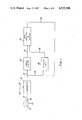
- FIG. 2 is a schematic diagram of an embodiment of the FIG. 1 system.
- FIG. 3 is a flow chart of the program implemented in the microprocessor of FIG. 2.
- FIG. 4 is a flow chart of a further program which may be implemented in the FIG. 2 microprocessor.
- FIG. 5 is a schematic diagram of a second system in accordance with the invention.
- FIG. 6 is a supplemental flow chart for the FIG. 5 system.
- shaft 10 includes at least one indicium for rotation therewith, slug indicium 12 being shown and suitably threaded onto shaft 10.
- a transducer 14 is disposed in fixed spatial relation to shaft 10 and positioned at a preselected location such that the field of sensitivity or view of the transducer encompasses the path of rotation of indicium 12 to generate a discrete output signal upon each passage of the indicium therethrough, thus providing a succession of signals.
- the output signals of transducer 14 are conducted over line 16 to comparator 18 which is supplied with a reference datum level input (REF) over line 20.
- Output signals of the comparator which correspond to the transducer output signals with enhanced signal-to-noise ratio, are applied over line 22 to speed monitor 24 and over line 26 to selector gate 28.
- speed monitor 24 is operative to provide output indication on line 30 to rpm computer and display 32 that shaft speed is or is not less than a preselected minimum.
- Selector gate 28 is enabled by condition of output line 34 of rpm computer and display 32 to gate pairs of sequentially successive signals applied thereto onto output line 36 and hence to unit 32.
- Rpm computer and display 32 includes a counter for providing a count, at a frequency greatly in excess of the highest frequency at which the transducer can generate its output signals, selectively during the time period occurring between the signals constituting each successive pair of output signals of gate 28. Circuitry is included in unit 32 for the selection of such pairs of sequentially successive pulses and for effecting a division of the accumulated count to determine the shaft rpm. Display is then made of such determined rpm, and a further rpm measurement cycle is commenced for purposes of updating actual rpm.
- Comparator 18 may be an operational amplifier of type LM741, available from National Semiconductor, line 20 deriving the REF potential from the junction of resistors R1 and R2, typically 210K and 68K, R1 being connected to +18 v. and R2 being tied to ground.
- Line 20 is connected to pin two of the LM741 and line 16 is connected to pin three.
- Pin six of the LM741 is connected to the junction of lines 22 and 26 through resistor R3 (330 ohms) andd diode D1, Zener diode D2 and resistor R4 (150 ohms) being connected as indicated to ground.
- Pins seven and four of the LM741 are connected to +18 v. and -18 v., respectively.
- Selector gate 28 may be a pulse triggered flip-flop (F/F), of type 5472, available from Signetics, line 26 being connected to the F/F CP input (pin twelve) and line 34 being connected to the F/F SD input (pin thirteen).
- the Q output (pin eight) of the F/F is connected to line 36.
- the logic of the 5472 F/F calls for the Q output (line 36) to be LO (zero volts) when line 34 is HI (+5 v.) and line 26 goes HI, i.e., applies a positive going clock pulse to the F/F CP input terminal.
- line 34 thereafter goes LO
- line 36 goes HI.
- Rpm computer and display unit 32 includes microprocessor (CPU) 38, which may be of type 8748, available from Intel.
- CPU 38 The program implemented by CPU 38 is discussed in connection with FIG. 3 below and is set forth in machine language hereinafter. Connections are made to the 8748 unit as follows. Pins twenty-six and forty are connected to +5 v. decoupled to ground through a one-tenth microfarad capacitor. A three megahertz crystal oscillator is connected across pins two and three and the latter pin is connected to ground through a twenty-two picafarad capacitor. Pin four, the RESET or initializing input, is connected to the junction of a 10K resistor (R5) and a one microfarad capacitor (CI), the former being tied to +5 v.
- R5 10K resistor
- CI microfarad capacitor
- Line 36 is connected to pin six.
- Line 30 is connected to pin thirty-nine. Pins seven and twenty are grounded.
- Output signals are furnished on pins twenty-one through twenty-four, respectively to lines 40-46 which comprise a four-bit bus for input to expander 48.
- Line 50 furnishes an output strobe to expander 48 and is connected to pin 25 of the 8748 CPU.
- Expander 48 may be of type 8243, available from Intel, and functions to receive and input through a four-bit port which serves as an interface to the 8748 CPU.
- lines 40-46 are connected to the expander pins eleven through eight.
- Pin seven of the expander is connected to line 50 and, as this line has a HI to LO transition, this signifies that address and control are available on lines 40-46.
- Three of the expander three four-bit output ports are used in FIG. 2, one being defined by pins seventeen through twenty which are connected to lines 52a, a second being defined by pins one and twenty-one through twenty-three which are connected to lines 52b, and a third being defined by pins two through five which are connected to lines 52c.
- Pin thirteen provides a low impedance latched output after a write operation, thereby furnishing a control signal on line 34 to selector gate 28.
- Decoder/Driver units 54, 56 and 58 may be of type 5477A, available from Signetics and adapted to accept four-bit BCD data and provide seven active decoded output signals to directly drive seven-segment incandescent displays. Pins seven, one, two and six of the 5477A units are connected in respective sets to lines 52a, 52b and 52c. Lines 60, 62 and 64 connect the decoded output signals to display units 66, 68 and 70, which may be of type 5082-7751, available from Hewlett Packard.
- START step 72 effects step 74 wherein the output registers of CPU 38 are reset to zero.
- Step 76 provides for display of the contents of the CPU 38 output registers, in this start-up case, zeroes.
- step 86 calls for another countercycle. If INT ⁇ 0, step 88 occurs to bring on a discontinuance of counting and a division, wherein the accumulated count is divided by a constant to determine rpm and binary to BCD conversion of the quotient is effected. Step 90 brings on an updating of the display to the calculated rpm.
- line 36 is active on the occurrence of each line 26 pulse during time periods in which line 34 is H1.
- Line 34 goes HI upon the conveyance of quotient data from CPU 38 to expander 50.
- the CPU 38 pin (pin six) to which selector gate 28 output) goes, is identified in the 8748 microprocessor as INT. This is an interrupt input, i.e., it initiates an interrupt if interrupt is enabled. Interrupt is disabled upon reset. In the detailed program set forth below, interrupt is enabled following step 74 (FIG. 3).
- the INT pin is repetitively consulted per the program in steps 78 for a first selector gate output and in step 84 for the next sequentially successive selector gate output.
- CPU 38 ignores the next succeeding selector gate output pulse or pulses to obtain uninterrupted computation time and then establishes conditions, by control of line 34, for further pulse pair selection and updating computation.
- the invention includes system capability for discontinuing rpm determination if rpm falls below a preselected limit, e.g., if the motor driving the shaft under observation should decelerate under a turn off or loss of power condition.
- speed monitor 24 (FIG. 2) may be a dual retriggerable monostable multivibrator of type 54LS123, available from Signetics.
- the self-cycle time of this unit is established by R6 and C2, typically 820K and 4.7 microfarads.
- the junction of R6 and C2 is connected to pin fifteen of the 54LS123.
- C2 is also connected to input pin fourteen and line 30 is connected to output pin thirteen. Pins three and sixteen are connected to +5 v., and pins one and eight are grounded.
- Line 22 is connected to pin 2.
- line 30 In operation of monitor 24, as line 22 goes HI, line 30 is set to HI. If the time period established by R6 and C2 now expires without line 22 again going HI, line 30 is set to LO. Conversely, line 30 continues at HI setting if line 22 renews a HI state prior to expiration of the R6 and C2 time period.
- Line 30 is connected to input pin thirty-nine of the 8748 microprocessor, a pin labeled "T1" and testable using one of the instructions (JNT1) of the instruction set of the 8748 ROM.
- JNT1 the instructions of the instruction set of the 8748 ROM.
- Steps 92, 94 and 96 of FIG. 4 track the opening operations of FIG. 3.
- step 105 makes inquiry of line 36, looking for the next successive pulse. Where the pulse is not present, inquiry is again made as to the state of line 30 in step 107 and step 110 repeats the count cycle. If T1 is zero, step 112 returns the operation to step 94. Upon the detecting in step 105 of the next successive line 36 pulse, the operation advances to rpm determination in step 114 and to display in step 116.
- the system of FIGS. 1 and 2 is extended to include capability for accepting input information as to a desired shaft rpm and for providing output indication of whether actual shaft rpm exceeds or is less than the desired rpm.
- thumb wheel switches S1-S4 identified by reference numerals 118 through 124, provide for output on lines 126a through 126d of from digital zero to digital 9999. As is indicated typically by resistor R7 at S3, each line is connected through a resistor to a voltage source.
- Expander 128, also of 8243 type above discussed, receives input from lines 126a-126d and provides a four-bit output on lines 132-138, responsive to a probe signal on line 132 and when a chip-select signal is present on line 140.
- Line 142 provides a chip-select signal to expander 48.
- CPU 38 is programmed to accept input from expander 128 by selecting expander 128 and strobing line 130 and to provide output to expander 48 by selecting expander 48 and strobing line 50, at the same set of input-output ports.
- CPU 38 yields output signals to driver/comparators of range indicating light-emitting diodes (LEDS) 144, 146 and 148 over lines 150, 152 and 154.
- LED 144 is activated whenever actual rpm is out of range.
- LED 146 indicates an over range condition and LED 148 indicates an under range condition.
- the range program of FIG. 6 is a subroutine occurring between steps 98 and 102 of the FIG. 4 program, i.e., following each rpm computation and preceding the succeeding rpm computation.
- Step 156 initiates the range subroutine and in steps 158 and 160, CPU 38 selects expander 128 and reads and stores the set rpm and allowable range.
- step 162 the computed rpm is taken from storage as is the set rpm and the difference therebetween is found.
- step 164 Inquiry is made in step 164 as to whether the set rpm exceeds the computed rpm. If no, step 166 provides for interchanging the storage locations of computed and set rpm and a parameter FO is set equal to one. Step 162 is now repeated and the step 164 output is necessarily yes. Step 168 makes inquiry as to whether the allowable range is less than the difference. If no, the LEDS are extinguished in step 170 and one returns (RET) to the FIG. 4 program. If yes, inquiry is made in step 172 of the state of FO. FO being one in the situation under discussion by practice of step 166 above, step 174 activates the over range LED.
- step 164 If in step 164, set rpm does exceed computed rpm, the program flows as above, except that step 172 is followed (FO not being one) by step 176 and the under range LED is activated.
- a low speed datum level of about thirty rpm may be selected by the abovesaid values for R6 and C2.
- Output speed determination may extend from thirty to three hundred rpm, with system operation discontinued at speeds of less than about thirty rpm.
- rpm determination is made from a first and a second sequentially successive output signal selected for gating, the next succeeding transducer output being ignored (not gated), and an updated rpm determination is made from a third gated signal, which is typically sequentially successive to the ignored signal, and a fourth gated signal, which is sequentially successive to the third signal.
Abstract
In determining shaft rpm (revolutions per minute), a transducer generates a succession of output signals, corresponding to the successive passages of a shaft indicium through the transducer field of view. Processing circuitry is provided for selecting a sequentially successive pair of transducer output signals and for computing rpm therefrom. Updated rpm is computed from a further pair of sequentially successive transducer output signals, both non-sequentially successive to the earlier selected signal pair.
Description
This invention relates to the measurement of rotational speed and pertains more particularly to the rapid determination of revolutions per minute (rpm) of rotative bodies in spatially limited environments.
The capability of determining shaft rotational speed in quite short time periods has several evident advantages, the primary of which is the ability to quick-correct departures of shaft rotational speed from a desired datum level, e.g., within several seconds.
Such quick-correct ability can readily be obtained by providing for direct discernment of shaft speed in a short interval. Typically, one provides a speed wheel having sixty teeth and rotative with the shaft. The teeth are sensed magnetically by a transducer which yields a discrete electrical signal upon the passage of each tooth through its field of view or sensitivity. The shaft revolutions per minute (rpm) can be known in a one second interval. Thus, if five teeth are observed by the transducer in one second, an electrical counter will be stepped accordingly to a five count. A sixty multiple thereof will produce output indication of three hundred rpm.
In various situations, space limitations preclude the use of the relatively bulky sixty-tooth speed wheel. Here, one looks to a single slug mounted on the shaft and functioning as a one-tooth speed wheel. As the transducer now can provide not more than one pulse per revolution, transducer pulses are counted over an expanded time period, e.g., one minute. This practice has serious disadvantages over that first-discussed. The one-minute time period which must pass before speed can be read is too time-consuming for various applications requiring alteration of rpm for different test conditions.
Further, one cannot accurately read rpm until two update cycles following introduction of a change in motor speed. By way of example, assume a motor shaft to be rotating at one hundred and fifty rpm and that its speed is to be changed to one hundred and eighty-five rpm. As adjustment is made to the speed setter, say a rotary dial, motor speed increases as motor drive current increases. During the overall time period, i.e., preadjustment, adjustment and post-adjustment, the transducer output signals being counted occur at various motor speeds--initially at one hundred and fifty rpm, next at a speed between one hundred and fifty rpm and one hundred and eighty rpm, and ultimately at a speed approaching or somewhat exceeding one hundred and eighty rpm. After a one minute period, the counter will indicate perhaps one hundred and fifty-eight rpm. Clearly, the counter output cannot be the actual shaft speed at the time of readout, since the counter input during the minute interval preceding readout is provided in part at shaft speeds less than such actual shaft speed at readout. Another cycle is required to accurately read out actual speed, and if actual shaft speed is not precisely the desired one hundred and eighty rpm, one or more further cycles are required. Evidently, this is an intolerable situation for applications in which shaft speed is to be changed accurately and quickly.
The present invention has as its primary object the provision of method and system accomodating ready and accurate determination of rotational speed in applications involving space limitations.
It is a more particular object of the invention to enable quick-correction of shaft rotational speed in space-limited applications.
In attaining the foregoing and other objects, the invention provides method and system wherein rpm measurement is based on computation stemming from the times of occurence of a selected sequentially successive pair of output signals of a shaft transducer, with the transducer output signal succeeding the selected such pair being dismissed from consideration. The system may provide for a continuing update of rotational speed by selecting further for processing another sequentially successive pair of transducer signals non-sequential to a prior selected pair. Since each determination of rpm is made on the basis of events in but a single shaft revolution, each determination is single-speed indicative and thus has verity.
In another aspect, the system may be set to monitor rpm within a predetermined rpm range and provide output indication of out of range rpm. In a still further aspect, the system may incorporate a self-shutdown feature when rpm diminishes to a level below a given level, e.g., the system may effect self-shutdown as a motor coasts to low rpm in the course of motor turnoff.
The foregoing and other features of the invention will be further understood from the following detailed description of preferred embodiments thereof and from the drawings wherein like reference numerals identify like items throughout.
FIG. 1 is a functional block diagram of a system in accordance with the invention.
FIG. 2 is a schematic diagram of an embodiment of the FIG. 1 system.
FIG. 3 is a flow chart of the program implemented in the microprocessor of FIG. 2.
FIG. 4 is a flow chart of a further program which may be implemented in the FIG. 2 microprocessor.
FIG. 5 is a schematic diagram of a second system in accordance with the invention.
FIG. 6 is a supplemental flow chart for the FIG. 5 system.
Referring to FIG. 1, shaft 10 includes at least one indicium for rotation therewith, slug indicium 12 being shown and suitably threaded onto shaft 10. A transducer 14 is disposed in fixed spatial relation to shaft 10 and positioned at a preselected location such that the field of sensitivity or view of the transducer encompasses the path of rotation of indicium 12 to generate a discrete output signal upon each passage of the indicium therethrough, thus providing a succession of signals.
The output signals of transducer 14 are conducted over line 16 to comparator 18 which is supplied with a reference datum level input (REF) over line 20. Output signals of the comparator, which correspond to the transducer output signals with enhanced signal-to-noise ratio, are applied over line 22 to speed monitor 24 and over line 26 to selector gate 28. As is discussed below in detail, speed monitor 24 is operative to provide output indication on line 30 to rpm computer and display 32 that shaft speed is or is not less than a preselected minimum. Selector gate 28 is enabled by condition of output line 34 of rpm computer and display 32 to gate pairs of sequentially successive signals applied thereto onto output line 36 and hence to unit 32.
Rpm computer and display 32 includes a counter for providing a count, at a frequency greatly in excess of the highest frequency at which the transducer can generate its output signals, selectively during the time period occurring between the signals constituting each successive pair of output signals of gate 28. Circuitry is included in unit 32 for the selection of such pairs of sequentially successive pulses and for effecting a division of the accumulated count to determine the shaft rpm. Display is then made of such determined rpm, and a further rpm measurement cycle is commenced for purposes of updating actual rpm.
The selection of suitable components for implementing the system of FIG. 1 will be seen by reference to the schematic diagram of FIG. 2.
Rpm computer and display unit 32 includes microprocessor (CPU) 38, which may be of type 8748, available from Intel. The program implemented by CPU 38 is discussed in connection with FIG. 3 below and is set forth in machine language hereinafter. Connections are made to the 8748 unit as follows. Pins twenty-six and forty are connected to +5 v. decoupled to ground through a one-tenth microfarad capacitor. A three megahertz crystal oscillator is connected across pins two and three and the latter pin is connected to ground through a twenty-two picafarad capacitor. Pin four, the RESET or initializing input, is connected to the junction of a 10K resistor (R5) and a one microfarad capacitor (CI), the former being tied to +5 v. and the latter to ground. Line 36 is connected to pin six. Line 30 is connected to pin thirty-nine. Pins seven and twenty are grounded. Output signals are furnished on pins twenty-one through twenty-four, respectively to lines 40-46 which comprise a four-bit bus for input to expander 48. Line 50 furnishes an output strobe to expander 48 and is connected to pin 25 of the 8748 CPU.
Decoder/ Driver units 54, 56 and 58 may be of type 5477A, available from Signetics and adapted to accept four-bit BCD data and provide seven active decoded output signals to directly drive seven-segment incandescent displays. Pins seven, one, two and six of the 5477A units are connected in respective sets to lines 52a, 52b and 52c. Lines 60, 62 and 64 connect the decoded output signals to display units 66, 68 and 70, which may be of type 5082-7751, available from Hewlett Packard.
In the flow chart of FIG. 3, START step 72 effects step 74 wherein the output registers of CPU 38 are reset to zero. Step 76 provides for display of the contents of the CPU 38 output registers, in this start-up case, zeroes. In step 78, inquiry is made as to the whether the INT input to CPU 38, i.e., the selector gate 28 output on line 36 is present. If not (INT=0), the inquiry is repeated in step 80. If yes (INT≠0), a counting cycle is commenced in step 82. Inquiry as to the state of line 36 is again made in step 84. If the selector gate output is nil, i.e., a full revolution of shaft 10 (FIG. 1) has not occurred and (INT=0), step 86 calls for another countercycle. If INT≠0, step 88 occurs to bring on a discontinuance of counting and a division, wherein the accumulated count is divided by a constant to determine rpm and binary to BCD conversion of the quotient is effected. Step 90 brings on an updating of the display to the calculated rpm.
Returning to FIG. 2 and the preceding discussion of the logic of selector gate 28, line 36 is active on the occurrence of each line 26 pulse during time periods in which line 34 is H1. Line 34 goes HI upon the conveyance of quotient data from CPU 38 to expander 50. The CPU 38 pin (pin six) to which selector gate 28 output) goes, is identified in the 8748 microprocessor as INT. This is an interrupt input, i.e., it initiates an interrupt if interrupt is enabled. Interrupt is disabled upon reset. In the detailed program set forth below, interrupt is enabled following step 74 (FIG. 3). The INT pin is repetitively consulted per the program in steps 78 for a first selector gate output and in step 84 for the next sequentially successive selector gate output. Once such pair of sequentially successive pulses is noted in CPU 38, i.e., selected as a pulse pair for rpm determination, the CPU ignores the next succeeding selector gate output pulse or pulses to obtain uninterrupted computation time and then establishes conditions, by control of line 34, for further pulse pair selection and updating computation.
In a further aspect, the invention includes system capability for discontinuing rpm determination if rpm falls below a preselected limit, e.g., if the motor driving the shaft under observation should decelerate under a turn off or loss of power condition. For this purpose, speed monitor 24 (FIG. 2) may be a dual retriggerable monostable multivibrator of type 54LS123, available from Signetics. The self-cycle time of this unit is established by R6 and C2, typically 820K and 4.7 microfarads. The junction of R6 and C2 is connected to pin fifteen of the 54LS123. C2 is also connected to input pin fourteen and line 30 is connected to output pin thirteen. Pins three and sixteen are connected to +5 v., and pins one and eight are grounded. Line 22 is connected to pin 2.
In operation of monitor 24, as line 22 goes HI, line 30 is set to HI. If the time period established by R6 and C2 now expires without line 22 again going HI, line 30 is set to LO. Conversely, line 30 continues at HI setting if line 22 renews a HI state prior to expiration of the R6 and C2 time period.
Assuming step 104 to have been reached, step 105 makes inquiry of line 36, looking for the next successive pulse. Where the pulse is not present, inquiry is again made as to the state of line 30 in step 107 and step 110 repeats the count cycle. If T1 is zero, step 112 returns the operation to step 94. Upon the detecting in step 105 of the next successive line 36 pulse, the operation advances to rpm determination in step 114 and to display in step 116.
In the embodiment shown in FIG. 5, the system of FIGS. 1 and 2 is extended to include capability for accepting input information as to a desired shaft rpm and for providing output indication of whether actual shaft rpm exceeds or is less than the desired rpm. For this purpose, thumb wheel switches S1-S4, identified by reference numerals 118 through 124, provide for output on lines 126a through 126d of from digital zero to digital 9999. As is indicated typically by resistor R7 at S3, each line is connected through a resistor to a voltage source. Expander 128, also of 8243 type above discussed, receives input from lines 126a-126d and provides a four-bit output on lines 132-138, responsive to a probe signal on line 132 and when a chip-select signal is present on line 140. Line 142 provides a chip-select signal to expander 48. CPU 38 is programmed to accept input from expander 128 by selecting expander 128 and strobing line 130 and to provide output to expander 48 by selecting expander 48 and strobing line 50, at the same set of input-output ports.
Referring jointly to the flow charts of FIGS. 4 and 6, the range program of FIG. 6 is a subroutine occurring between steps 98 and 102 of the FIG. 4 program, i.e., following each rpm computation and preceding the succeeding rpm computation. Step 156 initiates the range subroutine and in steps 158 and 160, CPU 38 selects expander 128 and reads and stores the set rpm and allowable range. In step 162, the computed rpm is taken from storage as is the set rpm and the difference therebetween is found.
Inquiry is made in step 164 as to whether the set rpm exceeds the computed rpm. If no, step 166 provides for interchanging the storage locations of computed and set rpm and a parameter FO is set equal to one. Step 162 is now repeated and the step 164 output is necessarily yes. Step 168 makes inquiry as to whether the allowable range is less than the difference. If no, the LEDS are extinguished in step 170 and one returns (RET) to the FIG. 4 program. If yes, inquiry is made in step 172 of the state of FO. FO being one in the situation under discussion by practice of step 166 above, step 174 activates the over range LED.
If in step 164, set rpm does exceed computed rpm, the program flows as above, except that step 172 is followed (FO not being one) by step 176 and the under range LED is activated.
In typical usage of the method and system of the invention, a low speed datum level of about thirty rpm may be selected by the abovesaid values for R6 and C2. Output speed determination may extend from thirty to three hundred rpm, with system operation discontinued at speeds of less than about thirty rpm. With the three megahertz crystal operation of CPU 38, it is typical that rpm determination is made from a first and a second sequentially successive output signal selected for gating, the next succeeding transducer output being ignored (not gated), and an updated rpm determination is made from a third gated signal, which is typically sequentially successive to the ignored signal, and a fourth gated signal, which is sequentially successive to the third signal.
As will be appreciated by those skilled in the arts, various changes may be introduced in the foregoing practices and embodiments without departing from the invention. For example, more than one indicium can be employed on the shaft with the processor programmed to accomodate such change. Also, the system and method may combine variously the several aspects noted above. The preferred embodiments and practices are thus intended in an illustrative and not in a limiting sense. The true spirit and scope of the invention is set forth in the claims, which follow Tables I and II below, setting forth machine language programs respectively for the flow charts of FIGS. 4 and 6.
TABLE I
__________________________________________________________________________
LOC
OBJ LINE
SOURCE STATEMENT
__________________________________________________________________________
0000 21 ORG 00H
0000
0430
22 JMP BEGIN
23 ;
0010 24 ORG 10H
0010
2E 25 LAD1: XCH A,R6
0011
23E0
26 MOV A, #0E0H
0013
3A 27 OUTL P2,A; ;SELECT
CONTROL CHIP
0014
3F 28 MOVD P7,A ;
SET INT =1
0015
27 29 CLR A
0016
2E 30 XCH A,R6
0017
2400
31 JMP LADJ ;
LEFT JUSTIFY
DIVISOR
32;
0030 33 ORG 30H
0030
2301
34 BEGIN: MOV A,#01H
0032
39 35 OUTL P1,A ;
TURN ON LOW LED
0033
B830
36 MOV R0,#30H
;R0 POINTS TO A
DATA MEMORY
LOCATION
0035
BC0F
37 MOV R4,#OFH
38
0037
B000
39 TURNON:
MOV @R0,#00H
0039
18 40 INC R0
003A
EC37
41 DJNZ R4,TURNON ;
CLEAR DATA MEMORY
LOCATIONS
003C
BD00
42 MOV R5,#00H
003E
BE00
43 MOV R6,#00H
0040
23E0
44 MOV A,#0E0H
0042
3A 45 OUTL P2,A;SELECT
CONTROL CHIP
0043
3F 46 MOVD P7,A
;SET INT -1
47 ;
0044
97 48 OUTPUT:
CLR C
0045
85 49 CLR F0
0046
A5 50 CLR F1
0047
B900
51 MOV R1,#00H
0049
BA00
52 MOV R2,300H
004B
BE00
53 MOV R6,300H
004D
5400
54 CALL DISPL ;
DISPLAY CALCULATED
RPM
004F
4630
55 JNT1 BEGIN ;
IF MOTOR OFF,
IGNORE RANGE
0051
5420
56 CALL RANGE ;
COMPARE CALCULATED
RPM TO SET RPM
0053
23E1
57 MOV A,#0E1H
0055
3A 58 OUTL P2,A ;
SELECT CONTROL CHIP
0056
3F 59 MOVD P7,A ; ENABLE INT
0057
27 60 CLR A
61 ;
0058
8670
62 WAIT: JN1 COUNT1 ;
STAY HERE TILL
FIRST SYNCH PULSE
005A
4630
63 JNT1 BEGIN ; IF T1 IS
LOW, THEN MOTOR
IS OFF
005C
0458
64 JMP WAIT
65 ;
0070 66 ORG 70H
0070
27 67 COUNT1:
CLR A
0071
3F 68 MOVD P7,A ; SET INT
0072
17 69 INC A
0073
3F 70 MOVD P7,A ; ENABLE INT
0074
27 71 CLR A
72 ;
0075
BB20
73 COUNT2:
MOV R3,#20H
74 ;
0077
8610
75 COUNT3:
JNI LAD1; TIME DELAY,
665 MSEC
0079
EB77
76 DJNZ R3, COUNT3
007B
0301
77 ADD A,#01H;COUNT PERIOD
OF REVOLUTION
007D
E675
78 JNC COUNT2
007F
97 79 CLR C
0080
1A 80 INC R2 ; R2 IS MSB OF
DIVISOR
0081
4630
81 JNT1 BEGIN;IF T1 IS LOW,
THEN MOTOR IS OFF
0083
0475
82 JMP COUNT 2
83 ;
84
;*********************************************
85 ;
86 ;
87 ;
THIS ROUTINE LEFT JUSTIFIES THE DIVISOR
IN
88 ;
PREPARATION FOR THE DIVISION ROUTINE
89 ;
90 ;
0100 91 ORG 100H
0100
29 92 LADJ: XCH A,R1 ;
PREPARE
FOR
DIVISION
0101
B801
93 MOV R0,#01H; R1 IS LSB
OF DIVISOR
0103
BE00
94 MOV R6,#00H ; R6 IS
LSB OF QUOTIENT
0105
BF00
95 MOV R7,#00H ; IS MSB
OF QUOTIENT
0107
BCC8
96 MOV R4,#0C8H ; R4 IS
LSB OF DIVIDEND
0109
BDAF
97 MOV R,5#0AFH ; R5 IS
MSB OF DIVIDEND
98 ;
010B
18 99 SHIFT: INC R0 ; LEFT ADJUST
THE DIVISOR
010C
F8 100 MOV A,R0 ; R0 IS THE
SHIFT COUNTER
010D
03EF
101 ADD A,#0EFH
010F
F6A0
102 KC TERR ; CARRY IS
AN ERROR
0111
0311
103 ADD A,#11H
0113
97 104 CLR C
0114
A8 105 MOV R0,A
0115
FA 106 MOV A,R2
0116
F225
107 JB7 DIV ; WHEN B7=1
DIVISOR IS LEFT
JUSTIFIED
0118
F7 108 RLC A
0119
AA 109 MOV R2,A
011A
F9 110 MOV A,R1
011B
F7 111 RLC A
011C
F621
112 JC INCC; THIS CARRIES
TO MSB OF QUOTIENT
113 ;
011E
A9 114 AR1: MOV R1,A
011F
240B
115 JMP SHIFT
116 ;
0121
1A 117 INCC: INC R2
0122
97 118 CLR C
0123
241E
119 JMP AR1
120 ;
121
;******************************************
122 ;
123 ;
124 ;
THE DIVISION ROUTINE:
125 ;
126 ;
0125
FD 127 DIV: MOV A,R5
0126
37 128 CPL A
0127
6A 129 ADD A,R2
0128
37 130 CPL A
0129
7658
131 JF1 CARRY
132 ;
012B
E632
133 R: JNC GTT
012D
97 134 CLR C
012E
85 135 CLR F0
012F
95 136 CPL F0
0130
243C
137 JMP ANS
138 ;
0132
AD 139 GTT: MOV R5,A
0133
FC 140 MOV A,R4
0134
37 141 CPL A
0135
69 142 ADD A,R1
0136
37 143 CPL A
0137
E63B
144 JNC OK
0139
97 145 CLR C
013A
CD 146 DEC R5
147 ;
013B
AC 148 OK: MOV R4,A
149 ;
013C
FE 150 ANS: MOV A,R6
013D
F7 151 RLC A
013E
AE 152 MOV R6,A
013F
FF 153 MOV A,R7
0140
F7 154 RLC A
0141
F6A6
155 JC TBEG
0143
B646
156 JF0 Q
0145
1E 157 INC R6
158 ;
0146
AF 159 Q: MOV R7,A
0147
85 160 CLR F0
0148
C8 161 DEC R0
0149
F8 162 MOV A,R0
014A
C65C
163 JZ DVDEND
014C
FC 164 MOV A,R4
014D
F7 165 RLC A
014E
AC 166 MOV R4,A
014F
FD 167 MOV A,R5
0150
F7 168 RLC A
0151
AD 169 MOV R5,A
0152
E625
170 JNC DIV
0154
A5 171 CLR F1
0155
B5 172 CPL F1
0156
2425
173 JMP DIV
174;
0158
97 175 CARRY: CLR C
0159
A5 176 CLR F1
015A
242B
177 JMP R
178 ;
015C
B830
179 DIVIDEND:
MOV R0,#30H ; SET
REGISTERS TO PERMIT
BCD CONV.
015E
FE 180 MOV A,R6
015F
28 181 XCH A,R0
0160
A9 182 MOV R1,A
0161
28 183 XCH A,R0
0162
BC03
184 MOV R4,#03H
185 ;
0164
B100
186 BCDCOA:
MOV @R1,#00H; BINARY TO
BCD CONVERSION
0166
19 187 INC R1
0167
EC64
188 DJNZ R4,BCDCOA
0169
BB10
189 MOV R3,10H
190 ;
016B
97 191 BCDCOB:
CLR C
016C
F7 192 RLC A
016D
2F 193 XCH A,R7
016E
F7 194 RLC A
016F
2F 195 XCH A,R7
0170
28 196 XCH A,R0
0171
A9 197 MOV R1,A
0172
28 198 XCH A,R0
0173
BC03
199 MOV R4,#03H
0175
AD 200 MOV R5,A
201 ;
0176
F1 202 BCDCOC:
MOV A,@R1
0177
71 203 ADDC A,@R1
0178
57 204 DA A
0179
A1 205 MOV @R1,A
017A
19 206 INC R1
017B
EC76
207 DJNZ R4,BCDCOC
017D
FD 208 MOV A,R5
017E
F6A6
209 JC TBEG
0180
EB6B
210 DJNZ R3,BCDCOB
0182
97 211 CLR C
212 ;
0183
F0 213 TANS: MOV A,@R0 ; TAKE BCD
ANS AND PUT IN
OUTPUT REGS
0184
2C 214 XCH A,R4 ; R4 IS TWO
LS DIGITS OF ANSWER
0185
18 215 INC R0
0186
FO 216 MOV A,@R0
0187
2D 217 XCH A,R5 ; R5 IS MS
OF ANSWER
0188
0444
218 JMP OUTPUT
219
01A0 220 ORG 1A0H
01A0
B830
221 TERR: MOV R0,#30H ; DATA
MEM 30H IS
MS DIGITS
01A2
2483
222 JMP TANS ; DATA MEM
32H IS LS DIGITS
223 ;
01A6 224 ORG 1A6H
01A6
0444
225 TBEG: JMP OUTPUT
226 ;
227
;************************************************
228 ;
229 ;
230 ;
THE FOLLOWING SUBROUTINES ARE USED BY
THE MAIN PROGRAM
231 ;
232 ;
0200 233 ORG 200H
0200
FC 234 DISPL: MOV A,R4 ; SUBROUTINE
TO DISPLAY ANSWER
0201
3E 235 MOVD P6,A; DISPLAY UNITS
0202
47 236 SWAP A
0203
3D 237 MOVD P5,A; DISPLAY TENS
0204
FD 238 MOV A,R5
0205
3C 239 MOVD P4,A; DISPLAY
HUNDREDS
0206
83 240 RET
241 ;
0220 242 ORG 220H; SUBROUTINE TO
CHECK THE RANGE
0220
B830
243 RANGE: MOV R0,#30H ; LOWER
BYTE IS ALWAYS LSD
0222
B932
244 MOV R1,#32H ; PUT CALC
RPM IN DATA MEM 32H
& 33H
0224
F0 245 MOV A,@R0
0225
A1 246 MOV @R1,A
0226
18 247 INC R0
0227
19 248 INC R1
0228
F0 249 MOV A,@R0
0229
A1 250 MOV @R1,A
022A
B834
251 MOV R0,#34H
022C
23D0
252 MOV A,#ODOH
022E
3A 253 OUTL P2,A ; SELECT
INPUT CHIP
022F
0C 254 MOVD A,P4
0230
0C 255 MOVD A,PA ; INPUT LS
DIGIT
0231
A0 256 MOVD @R0,A
0232
0D 257 MOVD A,P5
0233
0D 258 MOVD A,P5 ; INPUT
MIDDLE DIGIT
0234
47 259 SWAP A
0235
40 260 ORL A,@R0
0236
37 261 CPL A ; UNDO CPL
LOGIC OF SWITCH
0237
A0 262 MOV @R0,A ; DATA
MEMORY 34H IS
TWO LOWER DIGITS
0238
18 263 INC R0
0239
0E 264 MOVD A,P6
023A
0E 265 MOVD A,P6 ; INPUT MS
DIGIT
023B
37 266 CPL A
023C
530F
267 ANL A,#0FH ; UNDO CPL
LOGIC OF SWITCH
023E
A0 268 MOV @R0,A ; DATA
MEMORY 35H IS MS
DIGIT
023F
B838
269 MOV R0,#38H
0241
0F 270 MOVD A,P7
0242
0F 271 MOVD A,P7 ; INPUT
RANGE VALUE
0243
37 272 CPL A
0244
530F
273 ANL A,#0FH ; UNDO CPL
LOGIC OF SWITCH
0246
A0 274 MOV @R0,A ; DATA
MEMORY 38H & 39H IS
RANGE
0247
18 275 INC R0
0248
27 276 CLR A
0249
A0 277 MOV @R0,A ; CLEAR DATA
MEMORY 39H
278 ;
024A
B832
279 RANGE1 :
MOV R0,#32H ; R0
POINTS TO
SUBTRAHEND
024C
B936
280 MOV R1,#36H; R1 POINTS
TO DIFFERENCE
024E
5470
281 CALL SUBTR
0250
F656
282 JC RANGE 2 ; C=1 IF
SET>ACTUAL RPM
0252
5490
283 CALL SWITCH
0254
444A
284 JMP RANGE1
285 ;
0256
97 286 RANGE2:
CLR C
0257
B836
287 MOV R0,#36H
0259
B93A
288 MOV R1,#3AH
025B
5470
289 CALL SUBTR
025D
2304
290 MOV A,#04H
025F
F669
291 JC RANGE3 ; C=1 IF
RANGE>DIFFERENCE
0261
B667
292 JF0 OVRANG
293 ;
0263
2301
294 UNRANG:
MOV A,#01H ; BIT 0 IS
UNDER RANGE LED
0265
4469
295 JMP RANGE3 ; BIT 2 IS
TO P.C.
296 ;
0267
2302
297 OVERANG:
MOV A,#02 ; BIT 1 IS
OVER RANGE LED
298 ; ; BIT 2 IS TO P.C.
299 ;
0269
85 300 RANGE3:
CLR F0
026A
97 301 CLR C
026B
39 302 OUTL P1,A ; ACTIVATE
PROPER LINES
026C
83 303 RET
304 ;
0270 305 ORG 270H
0270
97 306 SUBTR: CLR C ; SUBTRACTION
OF BCD NUMBERS
0271
F0 307 MOV A,@R0
0272
18 308 INC R0
0273
18 309 INC R0 ; R0 POINTS TO
SET RPM
0274
37 310 CPL A
0275
039A
311 ADD A,#9AH
0277
70 312 ADDC A,@R0
0278
C8 313 DEC R0
0279
57 314 DA A
027A
A1 315 MOV @R1,A ; TWO LS
DIGITS OF
DIFFERENCE
027B
19 316 INC R1
027C
F0 317 MOV A,@R0
027D
18 318 INC R0
027E
18 319 INC R0
027F
37 320 CPL A
0280
1399
321 ADDC A,#99H
0282
70 322 ADDC A,@R0
0283
57 323 DA A
0284
A1 324 MOV @RA,A ; MS DIGIT
IS DIFFERENCE
0285
83 325 RET
326;
0290 327 ORG 290H ; SWITCH
CALC & SET RPM TO
GET POS ANS
0290
BA02
328 SWITCH:
MOV R2,#02H ; R2 IS
JUST A COUNTER
0292
B934
329 MOV R1,334H
0294
B832
330 MOV R0,#32H
331 ;
0296
F0 332 SWITC1:
MOV A,@R0
0297
21 333 XCH A,@R1
0298
A0 334 MOV @R0,A
0299
18 335 INC R0
029A
19 336 INC R1
029B
EA96
337 DJNZ R2,SWITC1
029D
85 338 CLR F0
0293
95 339 CPL F0
029F
83 340 RET
341 ;
342 END
USER SYMBOLS
ANS 013C
AR1 011E
BCDCOA OL64
BCDCOB 016B
COUNT2 0075
COUNT3 0077
DISPL 0200
DIV 0125
LADJ 0100
OK 013B
OUTPUT 0044
OVRANG 0267
RANGE2 0256
RANGE3 0269
SHIFT 01OB
SUBTR 0270
TERR 01A0
TURNON 0037
UNRANG 0263
WAIT 0058
BCDCOC 0176
BEGIN 0030
CARRY 0158
COUNT1 0070
DVDEND 015C
GTT 0132
INCC 0121 LAD1 0010
Q 0146
R 012B
RANGE 0220
RANGE1 024A
SWITC1 0296
SWITCH 0290
TANS 0183 TBEG 01A6
__________________________________________________________________________
                                  TABLE II
__________________________________________________________________________
LOC
   OBJ LINE
           SOURCE STATEMENT
__________________________________________________________________________
0000   1         ORG     00H
0000
   0430
       2         JMP     BEGIN
       3 ;
0010   4         ORG     10H
0010
   2E  5   LAD1: XCH     A,R6
0011
   27  6         CLR     A ; SET INT
0012
   3F  7         MOVD    P7,A
0013
   2E  8.        XCH     A,R6
0014
   2400
       9         JMP     LADJ
       10 ;
0030   11        ORG     30H
0030
   B830
       12  BEGIN:
                 MOV     R,#30H ; CLEAR
                         OUTPUT MEMORY
                         LOCATIONS
0032
   BC03
       13        MOV     R4,#03H
0034
   B000
       14  TURNON:
                 MOV     @R0,#00H
0036
   18  15        INC     R0
0037
   EC34
       16        DJNZ    R4,TURNON
0039
   BD00
       17        MOV     R5,#00H
003B
   BE00
       18        MOV     R6,#00H
003D
   27  19        CLR     A ; SET INT
003E
   3F  20        MOVD    P7,A
       21 ;
003F
   97  22  OUTPUT:
                 CLR     C
0040
   85  23        CLR     F0
0041
   A5  24        CLR     F1
0042
   B900
       25        MOV     R1,#00H
0044
   BA00
       26        MOV     R2,#00H
0046
   BE00
       27        MOV     R6,#00H
0048
   5400
       28        CALL    DISPL
004A
   5410
       29        CALL    DISEC
004C
   2301
       30        MOV     A,#01H ; ENABLE INT
004E
   3F  31        MOVD    P7,A
004F
   27  32        CLR     A
       33 ;
0050
   8670
       34  WAIT: JNI     COUNT1 ; STAY
                         HERE TILL
                         FIRST SYNCH PULSE
0052
   4630
       35        JNT1    BEGIN ; IF T1 IS
                         LOW, THEN MOTOR
                         IS OFF
0054
   0450
       36        JMP     WAIT
       37 ;
0070   38        ORG     70H
0070
   27  39  COUNT1:
                 CLR     A ; SET INT
0071
   3F  40        MOVD    P7,A
0072
   17  41        INC     A ; ENABLE INT
0073
   3F  42        MOVD    P7,A
0074
   27  43        CLR     A
       44 ;
0075
   BB20
       45  COUNT2:
                 MOV     R3,#20H
       46 ;
0077
   8610
       47  COUNT3:
                 JNI     LAD1 ; TIME DELAY,
                         665 MSEC
0079
   EB77
       48        DJNZ    R3,COUNT 3
007B
   0301
       49        ADD     A #01H ; COUNT
                         PERIOD OF
                         REVOLUTION
007D
   F675
       50        JNC     COUNT 2
007F
   97  51        CLR     C
0080
   1A  52        INC     R2 ; R2 IS MSB OF
                         DIVISOR
0081
   4630
       53        JNT1    BEGIN ; IF T1 IS
                         LOW, THEN MOTOR
                         IS OFF
0083
   0475
       54        JMP     COUNT 2
       55 ;
0100   56        ORG     100H
0100
   29  57  LADJ: XCH     A,R1 ; PREPARE
                         FOR DIVISION
0101
   B801
       58        MOV     R0,#01H ; R1 IS
                         LSB OF DIVISOR
0103
   BE00
       59        MOV     R6,#01H ; R6 IS
                         LSB OF QUOTIENT
0105
   BF00
       60        MOV     R7,#00H ; R7 IS
                         MSB OF QUOTIENT
0107
   BCC8
       61        MOV     R4,#0C8H ; R4 IS
                         LSB OF DIVIDEND
0109
   BDAF
       62        MOV     R5,#0AFH ; R5 IS
                         MSB OF DIVIDEND
       63 ;
010B
   18  64  SHIFT:
                 INC     RO; LEFT ADJUST
                         THE DIVISOR
010C
   F8  65        MOV     A,R0 ; R0 IS THE
                         SHIFT COUNTER
010D
   03EF
       66        ADD     A,#0EFH
010F
   F6A0
       67        JC      TERR ; CARRY IS AN
                         ERROR
0111
   00  68        NOP
0112
   0311
       69        ADD     A,#11H
0114
   97  70        CLR     C
0115
   A8  71        MOV     R0,A
0116
   FA  72        MOV     A,R2
0117
   F226
       73        JB7     DIV
0119
   F7  74        RLC     A
011A
   AA  75        MOV     R2,A
011B
   F9  76        MOV     A,R1
011C
   F7  77        RLC     A
011D
   F622
       78        JC      INCC ; THIS CARRIES
                         TO MSB OF QUOTIENT
       79
011F
   A9  80  AR1:  MOV     R1,A
0120
   240B
       81        JMP     SHIFT
       82 ;
0122
   1A  83  INCC: INC     R2
0123
   97  84        CLR     C
0124
   241F
       85        JMP     AR1
       86 ;
0126
   FD  87  DIV:  MOV     A,R5 ; THE
                         DIVISION ROUTINE
0127
   37  88        CPL     A
0128
   6A  89        ADD     A,R2
0129
   37  90        CPL     A
012A
   7659
       91        JF1     CARRY
       92 ;
012C
   E633
       93  R:    JNC     GTT
012E
   97  94        CLR     C
012F
   85  95        CPL     F0
0130
   95  96        CPL     F0
0131
   243D
       97        JMP     ANS
       98 ;
0133
   AD  99  GT:   MOV     R5,A
0134
   FC  100       MOV     A,R4
0135
   37  101       CPL     A
0136
   69  102       ADD     A,R1
0137
   37  103       CPL     A
0138
   363C
       104       JNC     OK
013A
   97  105       CLR     C
013B
   CD  106       DEC     R5
       107 ;
013C
   AC  108 OK:   MOV     R4,A
       109 ;
013D
   FE  110 ANS:  MOV     A,R6
013E
   F7  111       RLC     A
013F
   AE  112       MOV     R6,A
0140
   FF  113       MOV     A,R7
0141
   F7  114       RLC     A
0142
   F6A6
       115       JC      TBEG
0144
   B647
       116       JFO     Q
0146
   1E  117       INC     R6
       118 ;
0147
   AF  119 Q:    MOV     R7,A
0148
   85  120       CLR     F0
0149
   C8  121       DEC     R0
014A
   F8  122       MOV     A,R0
014B
   C65D
       123       JZ      DVDEND
014D
   FC  124       MOV     A,R4
014E
   F7  125       RLC     A
0L4F
   AC  126       MOV     R4,A
0150
   FD  127       MOV     A,R5
0151
   F7  128       RLC     A
0152
   AD  129       MOV     R5,A
0153
   E626
       130       JNC     DIV
0155
   A5  131       CLR     F1
0156
   B5  132       CPL     F1
0157
   2426
       133       JMP     DIV
       134 ;
0159
   97  135 CARRY:
                 CLR     C
015A
   A5  136       CLR     F1
015B
   242C
       137       JMP     R
       138 ;
015D
   B830
       139 DVDEND:
                 MOV     R0,#30H ; SET
                         REGISTERS TO PERMIT
                         BCD CONV.
015F
   FE  140       MOV     A,R6
0160
   28  141       XCH     A,R0
0161
   A9  142       MOV     R1,A
0162
   28  143       XCH     A,R0
0163
   BC03
       144       MOV     R4,#03H
       145 ;
0165
   B100
       146 BCDCOA:
                 MOV     @R1,#00H ; BINARY
                         TO BCD CONVERSION
0167
   19  147       INC     R1
0168
   EC65
       148       DJNZ    R4,BCDCOA
016A
   BB10
       149       MOV     R3,#10H
       150 ;
016C
   97  151 BCDCOB:
                 CLR     C
016D
   F7  152       RLC     A
016E
   2F  153       XCH     A,R7
016F
   F7  154       RLC     A
0170
   2F  155       XCH     A,R7
0171
   28  156       XCH     A,R0
0172
   A9  157       MOV     R1,A
0173
   28  158       XCH     A,R0
0174
   BC03
       159       MOV     R4,#03H
0176
   AD  160       MOV     R5,A
       161 ;
0177
   F1  162 BCDCOC:
                 MOV     A,@R1
0178
   71  163       ADDC    A,@R1
0179
   57  164       DA      A
017A
   A1  165       MOV     @RA,A
017B
   19  166       INC     R1
017C
   EC77
       167       DJNZ    R4,BCDCOC
017E
   FD  168       MOV     A,R5
017F
   F6A6
       169       JC      TBEG
0181
   EB6C
       170       DJNZ    R3,BCDCOB
0183
   97  171       CLR     C
       172 ;
0184
   F0  173 TANS: MOV     A,@R0 ; TAKE BCD
                         ANS AND PUT IN
                         OUTPUT REGS
0185
   2C  174       XCH     A,R4 ; R4 IS TWO
                         LS DIGITS OF ANSWER
0186
   18  175       INC     R0
0187
   FO  176       MOV     A,@R0
0188
   2D  177       XCH     A,R5 ; R5 IS MS
                         DIGIT OF ANSWER
0189
   043F
       178       JMP     OUTPUT
       179 ;
01A0   180       ORG     1A0H
01A0
   B830
       181 TERR: MOV     RO,#30H
01A2
   2484
       182       JMP     TANS
       183 ;
01A6   184       ORG     1A6H
11A6
   043F
       185 TBEG: JMP     OUTPUT
       186 ;
0200   187       ORG     200H
0200
   FC  188 DISPL:
                 MOV     A,R4 ; SUBROUTINE
                         TO DISPLAY ANSWER
0201
   3E  189       MOVD    P6,A
0202
   47  190       SWAP    A
0203
   3D  191       MOVD    P5,A
0204
   FD  192       MOV     A,R5
0205
   3C  193       MOVD    P4,A
0206
   83  194       RET
       195 ;
0210   196       ORG     210H
0210
   BB61
       197 D1SEC:
                 MOV     R3,#61H; SUBROUTINE
                         TO DELAY 1 SECOND
0212
   23A7
       198       MOV     A,#0A7H
       199 ;
0214
   00  200 REP1: NOP
0215
   00  201       NOP
0216
   00  202       NOP
0217
   07  203       DEC     A
0218
   9614
       204       JNZ     REP1
021A
   EB14
       205       DJNZ    R3,REP1
021C
   83  206       RET
       207       END
USER SYMBOLS
ANS   013D
         AR1    011F
                   BCDCOA
                         0165
                            BCDCOB
                                  016C
COUNT2
      0075
         COUNT3 0077
                   D1SEC 0210
                            DISPL 0200
LAD1  0010
         LADJ   0100
                   OK    013C
                            OUTPUT
                                  003F
TANS  0184
         TBEG   01A6
                   TERR  01A0
                            TURNON
                                  0034
BCDCOC
      0177
         BEGIN  0030
                   CARRY 0159
                            COUNT1
                                  0070
DIV   0126
         DVDEND 0150
                   GTT   0133
                            INCC  0122
Q     0147
         R      012C
                   REP1  0214
                            SHIFT 010R
WAIT  0050
__________________________________________________________________________
Claims (13)
1. A method for determining the rotational speed of a body, comprising the steps of:
(a) disposing a sensible indicium for rotation with said body;
(b) generating a succession of output signals, each corresponding with a passage of said indicium through a preselected location in the rotational path thereof;
(c) initiating a count cycle upon the generation of a first such output signal and discontinuing said count cycle upon the generation of a second such output signal, said second output signal sequentially succeeding said first output signal;
(d) determining body rotational speed from the count accumulated in said step (c); and
(e) updating rotational speed determination by practice of the substeps of
(e) (1) initiating a further count cycle upon the generation of a third such output signal succeeding but non-sequential to said second output signal and discontinuing said further count cycle upon the generation of a fourth such output signal, said fourth output signal sequentially succeeding said third output signal, and
(e) (2) determining updated body rotational speed from the count accumulated in said step (e) (1).
2. The method claimed in claim 1 further including the further steps of establishing a predetermined time period following generation of said first output signal and discontinuing said count cycle if said second output signal is not generated within said time period.
3. The method claimed in claim 1 including the further steps of establishing a desired rotational speed for said body and providing output indication if such determined body speed does not correspond to such established speed.
4. The method claimed in claim 3 wherein said output indication is made selectively for determined body speeds over and under said established speed.
5. The method claimed in claim 2 including the further steps of establishing a desired rotational speed for said body and providing output indication if such determined body speed does not correspond to such established speed.
6. The method claimed in claim 5 wherein said output indication is made selectively for determined body speeds over and under said established speed.
7. A system for determining the rotational speed of a body having a sensible indicium rotatable therewith, comprising:
(a) transducer means for sensing each revolution of said indicium and generating an output signal indicative of each such sensing;
(b) selector means for receiving such output signals and responsive to a control signal for gating selective such received signals therethrough; (and)
(c) processor means for receiving such gated signals and
(1) generating (said) a first such control signal for effecting gating of a pair of said output signals through said selector means, one signal of said pair being sequentially successive to the other signal of said pair,
(2) determining said body rotational speed from the difference in the times of occurrence of said one and said other of the signals of said pair;
(3) generating a further such control signal for effecting gating of a further pair of said output signals through said selector means, one signal of said further pair being sequentially non-successive to the signals of said first-mentioned pair and the other signal of such further pair being sequentially successive to said one signal of said further pair; and
(4) determining updated body rotational speed from the difference in the times of occurrence of said one and said other of the signals of said further pair.
8. The system claimed in claim 7 further including means for establishing a predetermined time period following generation of the first-occurring of said output signals of such gated pair and for discontinuing operation of said system if the other signal of said pair is not generated within said time period.
9. The system claimed in claim 7 further including indicator means for establishing a desired rotational speed for said body and providing output indication if such determined speed does not correspond to such established speed.
10. The system claimed in claim 9 wherein said indicator means provides output indication of whether said determined speed is over or under said established speed.
11. The system claimed in claim 8 further including indicator means for establishing a desired rotational speed for said body and providing output indication if such determined speed does not correspond to such established speed.
12. The system claimed in claim 11 wherein said indicator means provides output indication of whether said determined speed is over or under said established speed.
13. In combination, for determining the rotational speed of a body having a sensible indicium rotatable therewith, comprising:
(a) transducer means for sensing each revolution of said indicium and generating an output signal indicative of each such sensing;
(b) selector means for receiving each such means (a) output signal and responsive to a control signal for gating selective but not all of such received means (a) output signals therethrough;
(c) means for generating said control signals for such selective gating and for applying same to said means (b); and
(d) means for receiving such signals gated selectively through said means (b) for determining body rotational speed therefrom.
Priority Applications (1)
| Application Number | Priority Date | Filing Date | Title |
|---|---|---|---|
| US06/399,320 US4535288A (en) | 1982-07-19 | 1982-07-19 | Method and system for rotary speed determination |
Applications Claiming Priority (1)
| Application Number | Priority Date | Filing Date | Title |
|---|---|---|---|
| US06/399,320 US4535288A (en) | 1982-07-19 | 1982-07-19 | Method and system for rotary speed determination |
Publications (1)
| Publication Number | Publication Date |
|---|---|
| US4535288A true US4535288A (en) | 1985-08-13 |
Family
ID=23579091
Family Applications (1)
| Application Number | Title | Priority Date | Filing Date |
|---|---|---|---|
| US06/399,320 Expired - Fee Related US4535288A (en) | 1982-07-19 | 1982-07-19 | Method and system for rotary speed determination |
Country Status (1)
| Country | Link |
|---|---|
| US (1) | US4535288A (en) |
Cited By (8)
| Publication number | Priority date | Publication date | Assignee | Title |
|---|---|---|---|---|
| US4633423A (en) * | 1984-03-27 | 1986-12-30 | Storage Technology Corporation | Coherent error suppression in digital tachometers and the like |
| US4796210A (en) * | 1985-07-05 | 1989-01-03 | Veglia | Method of displaying the speed and distance on board a motor vehicle |
| US4811255A (en) * | 1986-03-21 | 1989-03-07 | Horizon Instruments, Inc. | Tachometer, RPM processor, and method |
| US4885710A (en) * | 1987-06-25 | 1989-12-05 | Delco Electronics Corporation | Method and apparatus for low speed estimation |
| US4972332A (en) * | 1987-07-28 | 1990-11-20 | Caterpillar Inc. | Apparatus for determining the speed, angular position and direction of rotation of a rotatable shaft |
| US5170365A (en) * | 1985-12-12 | 1992-12-08 | General Electric Company | Propeller speed and phase sensor |
| US6591200B1 (en) | 1998-06-16 | 2003-07-08 | M.E.A. Motor Inspection Ltd. | Method and system for performance testing of rotating machines |
| US6799140B2 (en) * | 2000-02-28 | 2004-09-28 | Schneider Electric Industries Sa | Detector for monitoring rotation |
Citations (2)
| Publication number | Priority date | Publication date | Assignee | Title |
|---|---|---|---|---|
| US4323976A (en) * | 1978-08-09 | 1982-04-06 | Alfa Romeo S.P.A. | Electronic device for taking the speed of a rotating member |
| US4336497A (en) * | 1979-03-14 | 1982-06-22 | Lucas Industries Limited | Acceleration sensor |
-
1982
- 1982-07-19 US US06/399,320 patent/US4535288A/en not_active Expired - Fee Related
Patent Citations (2)
| Publication number | Priority date | Publication date | Assignee | Title |
|---|---|---|---|---|
| US4323976A (en) * | 1978-08-09 | 1982-04-06 | Alfa Romeo S.P.A. | Electronic device for taking the speed of a rotating member |
| US4336497A (en) * | 1979-03-14 | 1982-06-22 | Lucas Industries Limited | Acceleration sensor |
Cited By (8)
| Publication number | Priority date | Publication date | Assignee | Title |
|---|---|---|---|---|
| US4633423A (en) * | 1984-03-27 | 1986-12-30 | Storage Technology Corporation | Coherent error suppression in digital tachometers and the like |
| US4796210A (en) * | 1985-07-05 | 1989-01-03 | Veglia | Method of displaying the speed and distance on board a motor vehicle |
| US5170365A (en) * | 1985-12-12 | 1992-12-08 | General Electric Company | Propeller speed and phase sensor |
| US4811255A (en) * | 1986-03-21 | 1989-03-07 | Horizon Instruments, Inc. | Tachometer, RPM processor, and method |
| US4885710A (en) * | 1987-06-25 | 1989-12-05 | Delco Electronics Corporation | Method and apparatus for low speed estimation |
| US4972332A (en) * | 1987-07-28 | 1990-11-20 | Caterpillar Inc. | Apparatus for determining the speed, angular position and direction of rotation of a rotatable shaft |
| US6591200B1 (en) | 1998-06-16 | 2003-07-08 | M.E.A. Motor Inspection Ltd. | Method and system for performance testing of rotating machines |
| US6799140B2 (en) * | 2000-02-28 | 2004-09-28 | Schneider Electric Industries Sa | Detector for monitoring rotation |
Similar Documents
| Publication | Publication Date | Title |
|---|---|---|
| US4535288A (en) | Method and system for rotary speed determination | |
| US4109312A (en) | Method and apparatus for measuring and indicating the unbalance of a rotor | |
| US4281388A (en) | Tachometer | |
| JPH01320424A (en) | Apparatus for detecting position of mobile machine element | |
| US4404648A (en) | Method for controlling an instrument panel display | |
| US3888116A (en) | Digital torquemeter and the like | |
| KR930002719B1 (en) | Apparatus and method for increasing the accuracy of the encoder output | |
| GB1099928A (en) | Speed detection | |
| GB1511141A (en) | Apparatus for use in balancing wheels | |
| KR900002511B1 (en) | Speed detecting device | |
| JPS5953505B2 (en) | Rotation speed detection method | |
| JPH03167476A (en) | Number of rotations indicator | |
| JPH01320468A (en) | Method and apparatus for measuring revolutions of machine | |
| US3820395A (en) | Flowmeter | |
| JPH049266B2 (en) | ||
| SU1837782A3 (en) | Sausage filling syringe | |
| JPS62265573A (en) | Revolution detector for shaft | |
| SU717527A1 (en) | Device for measuring textile thread length on warping machine | |
| JPS63284473A (en) | Digital tachometer | |
| SU1024846A1 (en) | Rotation speed digital meter | |
| JPH0743653Y2 (en) | Stroboscope | |
| SU388229A1 (en) | ALL-UNION: "tHTtKi- ^ KflH ** F ^^^ | |
| SU1117533A1 (en) | Device for checking number of revolutions | |
| SU1436075A1 (en) | Apparatus for measuring speed of rotation | |
| SU1278718A1 (en) | Transducer of angular position and rotational speed of shaft |
Legal Events
| Date | Code | Title | Description |
|---|---|---|---|
| AS | Assignment |
Owner name: MAGNETIC ANALYSIS CORPORATION 535 SOUTH FOURTH AVE Free format text: ASSIGNMENT OF ASSIGNORS INTEREST.;ASSIGNOR:VITULLI, JOSEPH L. JR.;REEL/FRAME:004027/0521 Effective date: 19820712 |
|
| REMI | Maintenance fee reminder mailed | ||
| LAPS | Lapse for failure to pay maintenance fees | ||
| STCH | Information on status: patent discontinuation |
Free format text: PATENT EXPIRED DUE TO NONPAYMENT OF MAINTENANCE FEES UNDER 37 CFR 1.362 |
|
| FP | Lapsed due to failure to pay maintenance fee |
Effective date: 19890813 |