US4536373A - Contact structure for use in catalytic distillation - Google Patents
Contact structure for use in catalytic distillation Download PDFInfo
- Publication number
- US4536373A US4536373A US06/543,440 US54344083A US4536373A US 4536373 A US4536373 A US 4536373A US 54344083 A US54344083 A US 54344083A US 4536373 A US4536373 A US 4536373A
- Authority
- US
- United States
- Prior art keywords
- catalyst
- tray
- containers
- distillation
- reaction
- Prior art date
- Legal status (The legal status is an assumption and is not a legal conclusion. Google has not performed a legal analysis and makes no representation as to the accuracy of the status listed.)
- Expired - Lifetime
Links
- 238000004821 distillation Methods 0.000 title claims abstract description 50
- 230000003197 catalytic effect Effects 0.000 title abstract description 18
- 239000003054 catalyst Substances 0.000 claims abstract description 77
- 239000007788 liquid Substances 0.000 claims abstract description 21
- 239000007787 solid Substances 0.000 claims description 6
- 239000004744 fabric Substances 0.000 claims description 5
- 229920003023 plastic Polymers 0.000 claims description 5
- 239000004033 plastic Substances 0.000 claims description 5
- 239000011152 fibreglass Substances 0.000 claims description 2
- 238000006243 chemical reaction Methods 0.000 abstract description 41
- 238000000034 method Methods 0.000 abstract description 14
- 239000007791 liquid phase Substances 0.000 abstract description 12
- 239000011541 reaction mixture Substances 0.000 abstract description 8
- 238000005194 fractionation Methods 0.000 abstract description 5
- 239000000376 reactant Substances 0.000 abstract description 4
- OKKJLVBELUTLKV-UHFFFAOYSA-N Methanol Chemical compound OC OKKJLVBELUTLKV-UHFFFAOYSA-N 0.000 description 24
- 239000000463 material Substances 0.000 description 20
- VQTUBCCKSQIDNK-UHFFFAOYSA-N Isobutene Chemical compound CC(C)=C VQTUBCCKSQIDNK-UHFFFAOYSA-N 0.000 description 14
- 229920000642 polymer Polymers 0.000 description 8
- 125000000542 sulfonic acid group Chemical group 0.000 description 7
- 239000002245 particle Substances 0.000 description 6
- 239000000047 product Substances 0.000 description 6
- 229910001220 stainless steel Inorganic materials 0.000 description 6
- AKEJUJNQAAGONA-UHFFFAOYSA-N sulfur trioxide Chemical compound O=S(=O)=O AKEJUJNQAAGONA-UHFFFAOYSA-N 0.000 description 6
- BZLVMXJERCGZMT-UHFFFAOYSA-N Methyl tert-butyl ether Chemical compound COC(C)(C)C BZLVMXJERCGZMT-UHFFFAOYSA-N 0.000 description 5
- 238000009835 boiling Methods 0.000 description 5
- 238000006555 catalytic reaction Methods 0.000 description 5
- -1 i.e. Chemical compound 0.000 description 5
- 239000011347 resin Substances 0.000 description 5
- 229920005989 resin Polymers 0.000 description 5
- 239000010935 stainless steel Substances 0.000 description 5
- QAOWNCQODCNURD-UHFFFAOYSA-N sulfuric acid Substances OS(O)(=O)=O QAOWNCQODCNURD-UHFFFAOYSA-N 0.000 description 5
- 229920002554 vinyl polymer Polymers 0.000 description 5
- 150000001875 compounds Chemical class 0.000 description 4
- 229920001577 copolymer Polymers 0.000 description 4
- 238000006266 etherification reaction Methods 0.000 description 4
- 238000006317 isomerization reaction Methods 0.000 description 4
- 239000000203 mixture Substances 0.000 description 4
- 238000006116 polymerization reaction Methods 0.000 description 4
- KAKZBPTYRLMSJV-UHFFFAOYSA-N Butadiene Chemical group C=CC=C KAKZBPTYRLMSJV-UHFFFAOYSA-N 0.000 description 3
- 125000003118 aryl group Chemical group 0.000 description 3
- RTZKZFJDLAIYFH-UHFFFAOYSA-N ether Substances CCOCC RTZKZFJDLAIYFH-UHFFFAOYSA-N 0.000 description 3
- 229930195733 hydrocarbon Natural products 0.000 description 3
- 150000002430 hydrocarbons Chemical class 0.000 description 3
- 229910052751 metal Inorganic materials 0.000 description 3
- 239000002184 metal Substances 0.000 description 3
- 239000000843 powder Substances 0.000 description 3
- MYRTYDVEIRVNKP-UHFFFAOYSA-N 1,2-Divinylbenzene Chemical compound C=CC1=CC=CC=C1C=C MYRTYDVEIRVNKP-UHFFFAOYSA-N 0.000 description 2
- VXNZUUAINFGPBY-UHFFFAOYSA-N 1-Butene Chemical compound CCC=C VXNZUUAINFGPBY-UHFFFAOYSA-N 0.000 description 2
- HIXDQWDOVZUNNA-UHFFFAOYSA-N 2-(3,4-dimethoxyphenyl)-5-hydroxy-7-methoxychromen-4-one Chemical compound C=1C(OC)=CC(O)=C(C(C=2)=O)C=1OC=2C1=CC=C(OC)C(OC)=C1 HIXDQWDOVZUNNA-UHFFFAOYSA-N 0.000 description 2
- 239000004215 Carbon black (E152) Substances 0.000 description 2
- LFQSCWFLJHTTHZ-UHFFFAOYSA-N Ethanol Chemical compound CCO LFQSCWFLJHTTHZ-UHFFFAOYSA-N 0.000 description 2
- UQSXHKLRYXJYBZ-UHFFFAOYSA-N Iron oxide Chemical compound [Fe]=O UQSXHKLRYXJYBZ-UHFFFAOYSA-N 0.000 description 2
- CPLXHLVBOLITMK-UHFFFAOYSA-N Magnesium oxide Chemical compound [Mg]=O CPLXHLVBOLITMK-UHFFFAOYSA-N 0.000 description 2
- 239000004677 Nylon Substances 0.000 description 2
- PPBRXRYQALVLMV-UHFFFAOYSA-N Styrene Chemical compound C=CC1=CC=CC=C1 PPBRXRYQALVLMV-UHFFFAOYSA-N 0.000 description 2
- 239000002253 acid Substances 0.000 description 2
- 150000001336 alkenes Chemical class 0.000 description 2
- 230000029936 alkylation Effects 0.000 description 2
- 238000005804 alkylation reaction Methods 0.000 description 2
- VSCWAEJMTAWNJL-UHFFFAOYSA-K aluminium trichloride Chemical compound Cl[Al](Cl)Cl VSCWAEJMTAWNJL-UHFFFAOYSA-K 0.000 description 2
- 239000002585 base Substances 0.000 description 2
- 239000011324 bead Substances 0.000 description 2
- 230000005465 channeling Effects 0.000 description 2
- 239000007795 chemical reaction product Substances 0.000 description 2
- 238000006471 dimerization reaction Methods 0.000 description 2
- BDAGIHXWWSANSR-UHFFFAOYSA-N methanoic acid Natural products OC=O BDAGIHXWWSANSR-UHFFFAOYSA-N 0.000 description 2
- 229920001778 nylon Polymers 0.000 description 2
- 239000011236 particulate material Substances 0.000 description 2
- 239000012858 resilient material Substances 0.000 description 2
- 239000011949 solid catalyst Substances 0.000 description 2
- HIFJUMGIHIZEPX-UHFFFAOYSA-N sulfuric acid;sulfur trioxide Chemical compound O=S(=O)=O.OS(O)(=O)=O HIFJUMGIHIZEPX-UHFFFAOYSA-N 0.000 description 2
- NWUYHJFMYQTDRP-UHFFFAOYSA-N 1,2-bis(ethenyl)benzene;1-ethenyl-2-ethylbenzene;styrene Chemical compound C=CC1=CC=CC=C1.CCC1=CC=CC=C1C=C.C=CC1=CC=CC=C1C=C NWUYHJFMYQTDRP-UHFFFAOYSA-N 0.000 description 1
- KEQGZUUPPQEDPF-UHFFFAOYSA-N 1,3-dichloro-5,5-dimethylimidazolidine-2,4-dione Chemical compound CC1(C)N(Cl)C(=O)N(Cl)C1=O KEQGZUUPPQEDPF-UHFFFAOYSA-N 0.000 description 1
- ZCKODQRJCONMMC-UHFFFAOYSA-N 1-[2,3-bis(ethenyl)phenoxy]-2,3-bis(ethenyl)benzene Chemical compound C=CC1=CC=CC(OC=2C(=C(C=C)C=CC=2)C=C)=C1C=C ZCKODQRJCONMMC-UHFFFAOYSA-N 0.000 description 1
- VTPNYMSKBPZSTF-UHFFFAOYSA-N 1-ethenyl-2-ethylbenzene Chemical compound CCC1=CC=CC=C1C=C VTPNYMSKBPZSTF-UHFFFAOYSA-N 0.000 description 1
- IGGDKDTUCAWDAN-UHFFFAOYSA-N 1-vinylnaphthalene Chemical compound C1=CC=C2C(C=C)=CC=CC2=C1 IGGDKDTUCAWDAN-UHFFFAOYSA-N 0.000 description 1
- ISRGONDNXBCDBM-UHFFFAOYSA-N 2-chlorostyrene Chemical compound ClC1=CC=CC=C1C=C ISRGONDNXBCDBM-UHFFFAOYSA-N 0.000 description 1
- OSWFIVFLDKOXQC-UHFFFAOYSA-N 4-(3-methoxyphenyl)aniline Chemical compound COC1=CC=CC(C=2C=CC(N)=CC=2)=C1 OSWFIVFLDKOXQC-UHFFFAOYSA-N 0.000 description 1
- 229920000742 Cotton Polymers 0.000 description 1
- 238000005727 Friedel-Crafts reaction Methods 0.000 description 1
- 229910000831 Steel Inorganic materials 0.000 description 1
- 239000004809 Teflon Substances 0.000 description 1
- 229920006362 Teflon® Polymers 0.000 description 1
- 239000003377 acid catalyst Substances 0.000 description 1
- 229910052782 aluminium Inorganic materials 0.000 description 1
- XAGFODPZIPBFFR-UHFFFAOYSA-N aluminium Chemical compound [Al] XAGFODPZIPBFFR-UHFFFAOYSA-N 0.000 description 1
- 150000001491 aromatic compounds Chemical class 0.000 description 1
- 229910052599 brucite Inorganic materials 0.000 description 1
- 239000001273 butane Substances 0.000 description 1
- 238000005341 cation exchange Methods 0.000 description 1
- 239000003729 cation exchange resin Substances 0.000 description 1
- 229940023913 cation exchange resins Drugs 0.000 description 1
- 150000001768 cations Chemical class 0.000 description 1
- XTHPWXDJESJLNJ-UHFFFAOYSA-N chlorosulfonic acid Substances OS(Cl)(=O)=O XTHPWXDJESJLNJ-UHFFFAOYSA-N 0.000 description 1
- 229910017052 cobalt Inorganic materials 0.000 description 1
- 239000010941 cobalt Substances 0.000 description 1
- GUTLYIVDDKVIGB-UHFFFAOYSA-N cobalt atom Chemical compound [Co] GUTLYIVDDKVIGB-UHFFFAOYSA-N 0.000 description 1
- KYYSIVCCYWZZLR-UHFFFAOYSA-N cobalt(2+);dioxido(dioxo)molybdenum Chemical compound [Co+2].[O-][Mo]([O-])(=O)=O KYYSIVCCYWZZLR-UHFFFAOYSA-N 0.000 description 1
- 238000007334 copolymerization reaction Methods 0.000 description 1
- 238000004132 cross linking Methods 0.000 description 1
- 238000000354 decomposition reaction Methods 0.000 description 1
- 238000006356 dehydrogenation reaction Methods 0.000 description 1
- QDOXWKRWXJOMAK-UHFFFAOYSA-N dichromium trioxide Chemical compound O=[Cr]O[Cr]=O QDOXWKRWXJOMAK-UHFFFAOYSA-N 0.000 description 1
- 239000002270 dispersing agent Substances 0.000 description 1
- 230000000694 effects Effects 0.000 description 1
- 230000032050 esterification Effects 0.000 description 1
- 238000005886 esterification reaction Methods 0.000 description 1
- 125000001033 ether group Chemical group 0.000 description 1
- 239000012530 fluid Substances 0.000 description 1
- NBVXSUQYWXRMNV-UHFFFAOYSA-N fluoromethane Chemical compound FC NBVXSUQYWXRMNV-UHFFFAOYSA-N 0.000 description 1
- UQSQSQZYBQSBJZ-UHFFFAOYSA-N fluorosulfonic acid Chemical compound OS(F)(=O)=O UQSQSQZYBQSBJZ-UHFFFAOYSA-N 0.000 description 1
- 235000019253 formic acid Nutrition 0.000 description 1
- 239000012634 fragment Substances 0.000 description 1
- 150000004820 halides Chemical class 0.000 description 1
- 239000002638 heterogeneous catalyst Substances 0.000 description 1
- 238000005984 hydrogenation reaction Methods 0.000 description 1
- 239000003456 ion exchange resin Substances 0.000 description 1
- 229920003303 ion-exchange polymer Polymers 0.000 description 1
- 230000001788 irregular Effects 0.000 description 1
- 239000000395 magnesium oxide Substances 0.000 description 1
- 150000002739 metals Chemical class 0.000 description 1
- 125000002496 methyl group Chemical group [H]C([H])([H])* 0.000 description 1
- 239000002808 molecular sieve Substances 0.000 description 1
- IJDNQMDRQITEOD-UHFFFAOYSA-N n-butane Chemical compound CCCC IJDNQMDRQITEOD-UHFFFAOYSA-N 0.000 description 1
- OFBQJSOFQDEBGM-UHFFFAOYSA-N n-pentane Natural products CCCCC OFBQJSOFQDEBGM-UHFFFAOYSA-N 0.000 description 1
- JRZJOMJEPLMPRA-UHFFFAOYSA-N olefin Natural products CCCCCCCC=C JRZJOMJEPLMPRA-UHFFFAOYSA-N 0.000 description 1
- 150000001451 organic peroxides Chemical class 0.000 description 1
- DBSDMAPJGHBWAL-UHFFFAOYSA-N penta-1,4-dien-3-ylbenzene Chemical compound C=CC(C=C)C1=CC=CC=C1 DBSDMAPJGHBWAL-UHFFFAOYSA-N 0.000 description 1
- JRKICGRDRMAZLK-UHFFFAOYSA-L persulfate group Chemical group S(=O)(=O)([O-])OOS(=O)(=O)[O-] JRKICGRDRMAZLK-UHFFFAOYSA-L 0.000 description 1
- 239000012071 phase Substances 0.000 description 1
- 229920000728 polyester Polymers 0.000 description 1
- 239000003505 polymerization initiator Substances 0.000 description 1
- 238000002360 preparation method Methods 0.000 description 1
- HJWLCRVIBGQPNF-UHFFFAOYSA-N prop-2-enylbenzene Chemical compound C=CCC1=CC=CC=C1 HJWLCRVIBGQPNF-UHFFFAOYSA-N 0.000 description 1
- BALXUFOVQVENIU-KXNXZCPBSA-N pseudoephedrine hydrochloride Chemical compound [H+].[Cl-].CN[C@@H](C)[C@@H](O)C1=CC=CC=C1 BALXUFOVQVENIU-KXNXZCPBSA-N 0.000 description 1
- 238000010992 reflux Methods 0.000 description 1
- 230000001105 regulatory effect Effects 0.000 description 1
- 230000000717 retained effect Effects 0.000 description 1
- 238000000926 separation method Methods 0.000 description 1
- URGAHOPLAPQHLN-UHFFFAOYSA-N sodium aluminosilicate Chemical compound [Na+].[Al+3].[O-][Si]([O-])=O.[O-][Si]([O-])=O URGAHOPLAPQHLN-UHFFFAOYSA-N 0.000 description 1
- 239000002904 solvent Substances 0.000 description 1
- 239000010959 steel Substances 0.000 description 1
- 230000001180 sulfating effect Effects 0.000 description 1
- 238000006277 sulfonation reaction Methods 0.000 description 1
- 230000008961 swelling Effects 0.000 description 1
- ZCUFMDLYAMJYST-UHFFFAOYSA-N thorium dioxide Chemical compound O=[Th]=O ZCUFMDLYAMJYST-UHFFFAOYSA-N 0.000 description 1
- 239000012808 vapor phase Substances 0.000 description 1
- 125000000391 vinyl group Chemical group [H]C([*])=C([H])[H] 0.000 description 1
Images

Classifications
-
- B—PERFORMING OPERATIONS; TRANSPORTING
- B01—PHYSICAL OR CHEMICAL PROCESSES OR APPARATUS IN GENERAL
- B01J—CHEMICAL OR PHYSICAL PROCESSES, e.g. CATALYSIS OR COLLOID CHEMISTRY; THEIR RELEVANT APPARATUS
- B01J8/00—Chemical or physical processes in general, conducted in the presence of fluids and solid particles; Apparatus for such processes
- B01J8/008—Details of the reactor or of the particulate material; Processes to increase or to retard the rate of reaction
-
- B—PERFORMING OPERATIONS; TRANSPORTING
- B01—PHYSICAL OR CHEMICAL PROCESSES OR APPARATUS IN GENERAL
- B01D—SEPARATION
- B01D3/00—Distillation or related exchange processes in which liquids are contacted with gaseous media, e.g. stripping
- B01D3/009—Distillation or related exchange processes in which liquids are contacted with gaseous media, e.g. stripping in combination with chemical reactions
-
- B—PERFORMING OPERATIONS; TRANSPORTING
- B01—PHYSICAL OR CHEMICAL PROCESSES OR APPARATUS IN GENERAL
- B01D—SEPARATION
- B01D3/00—Distillation or related exchange processes in which liquids are contacted with gaseous media, e.g. stripping
- B01D3/14—Fractional distillation or use of a fractionation or rectification column
- B01D3/16—Fractionating columns in which vapour bubbles through liquid
- B01D3/18—Fractionating columns in which vapour bubbles through liquid with horizontal bubble plates
- B01D3/20—Bubble caps; Risers for vapour; Discharge pipes for liquid
-
- B01J35/56—
-
- B—PERFORMING OPERATIONS; TRANSPORTING
- B01—PHYSICAL OR CHEMICAL PROCESSES OR APPARATUS IN GENERAL
- B01J—CHEMICAL OR PHYSICAL PROCESSES, e.g. CATALYSIS OR COLLOID CHEMISTRY; THEIR RELEVANT APPARATUS
- B01J2208/00—Processes carried out in the presence of solid particles; Reactors therefor
- B01J2208/00796—Details of the reactor or of the particulate material
- B01J2208/00805—Details of the particulate material
- B01J2208/00814—Details of the particulate material the particulate material being provides in prefilled containers
-
- B—PERFORMING OPERATIONS; TRANSPORTING
- B01—PHYSICAL OR CHEMICAL PROCESSES OR APPARATUS IN GENERAL
- B01J—CHEMICAL OR PHYSICAL PROCESSES, e.g. CATALYSIS OR COLLOID CHEMISTRY; THEIR RELEVANT APPARATUS
- B01J2208/00—Processes carried out in the presence of solid particles; Reactors therefor
- B01J2208/00796—Details of the reactor or of the particulate material
- B01J2208/00884—Means for supporting the bed of particles, e.g. grids, bars, perforated plates
Definitions
- the present invention relates to a contact structure to be used in catalytic reactions wherein the reaction and distillation of the reaction system are carried on concurrently in the same column.
- U.S. Pat. No. 2,403,672 discloses a process for catalytic isomerization wherein the upper two thirds of a distillation column is packed with a catalytic material in the column to fractionate the product.
- the present invention provides an alternative means to carry out a catalytic distillation wherein the catalyst is not the fractionation structure, but which does not have the disadvantages described above for alternative methods.
- the present invention further provides a means or system wherein the catalyst contact structure is present in the reactor distillation column and does not impede the flow of vapor or cause flooding.
- the present contact catalyst structure comprises a plurality of porous closed containers, containing therein solid particulate catalyst and clip means for holding and spacing said containers as a unit for disposition above a distillation tray of a distillation column and the process of conducting a catalyst reaction therewith.
- the solid particulate catalyst is contained in perforated or porous metal or plastic containers, such as a fine screen or similar material.
- the containers are supported above a conventional distillation tray so as to permit liquid flow through and past the containers, and also to permit vapor passage through the liquid. A sufficient level is maintained on the tray to essentially completely submerge the containers. In this way, the reactive liquid phase is contacted with both the solid catalyst and vapor.
- the process of the present invention is a method for concurrently conducting catalytic chemical reactions wherein the materials of the reaction mixture are separated by distillation and said materials are liquid or gaseous under the conditions of reaction; and fractionation of the reaction mixture comprising:
- a fixed bed catalyst consisting of a plurality of closed porous containers, containing therein particulate catalyst for said reaction, said containers being arranged as a unit and spaced apart, said unit of containers being disposed above a portion of said distillation trays of said distillation column reactor, whereby liquid on said tray covers said containers
- reaction and fractionation are occurring concurrently within said reactor, said reaction occurring in liquid phase and said reaction mixture being fractionated on said distillation trays.
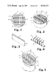
- FIG. 1 is an in-plan view of a contact catalyst structure according to the present invention positioned above a perforated sieve tray.
- FIG. 2 shows a perspective view of a cut-away distillation column reactor having a perforated sieve tray with a contact catalyst structure positioned thereon.
- FIG. 3 is a perspective view of one embodiment of a catalyst container.
- FIG. 4 is a perspective view of one embodiment of a container clip support.
- FIG. 5 shows a perspective view of a distillation column reactor having a sloping perforated sieve tray with a contac catalyst structure positioned thereon.
- FIG. 6 is a partial cut-away view of a distillation column reactor with contact catalyst structures of the present invention positioned therein in perspective.
- FIG. 7 is a partial perspective view of a distillation tray showing clips attached to an overflow weir for holding containers on the tray.
- a particular catalyst system of this type consists of a metal screen formed into a tube of rectangular cross section, filled with particulate solid catalyst and closed at the ends.
- Several such tubes may be supported on a distillation tray in a parallel array so that the liquid flow across the tray is either parallel to the tubes, or at right angles to them. If the flow is parallel, liquid flow is relatively unimpeded; if the flow is across the tubes, liquid is required to flow through the tubes from one side to the other. In the latter case, a sloping or staggered cascade tray is required to provide a gradient for flow. In either case, sieve-tray performations, vapor valves, or other openings are located in the tray deck between the tubes, so that the vapor flow is not restricted by the presence of the tubes of solid particulate material.
- the catalytic material may be any material appropriate for the reaction at hand, that is, it may be an acid catalyst or a basic catalyst or others such as catalytic metals and their oxides or halides suitable for a multitude of catalytic reactions and of course, heterogeneous with the reaction or fluids in the system.
- one reaction is the preparation of formic acid from methanol using iron oxide.
- Catalyst or “catalytic material” is used to include any solid particulate material which is recognized for the reaction under consideration as performing as a catalyst therein.
- the particle size of the catalytic material is from about 1 mm down through powders, as appropriate for the mesh of the container.
- the container will be made of a material having some rigidity such as wire mesh (screen wire) or plastic mesh, although less rigid materials such as cloth may be used.
- the cloth may be cotton, fiber glass, polyester, nylon and the like.
- the screen wire may be aluminum, steel, stainless steel and the like.
- the plastic mesh may be nylon, Teflon or the like.
- the mesh of the container is smaller than the catalyst particles contained therein.
- the wire mesh or plastic mesh are preferred because the rigid containers are more easily attached in the desired spaced array and the more open mesh of these materials allows greater flow of liquids into and through the containers.
- the mesh or threads per inch of the material used to make the container is such that the catalyst is retained therein and will not pass through the openings in the material.
- the catalyst particles are generally in the range of 0.25 to 1 mm, particles of about 0.15 mm size (diameter) or powders may be used and particles up to about 1/4 inch diameter may be employed in the containers.
- the particulate catalytic material may be a powder; however, it is preferably small irregular fragments or chunks, small beds or the like.
- the container has a generally elongated configuration, such as tubes, rectangular pockets and the like.
- the containers are arranged in a substantially parallel configuration which spaces between the containers. This is conveniently obtained by means of clips which may be attached to the distillation tray or attached to a member which may be disposed on or attached to the distillation tray.
- the present contact catalyst structure is particularly suitable for use with the cation exchange resins.
- Such resins include cation exchangers, which contain sulfonic acid groups, and which have been obtained by polymerization or copolymerization of aromatic vinyl compounds followed by sulfonation.
- aromatic vinyl compounds suitable for preparing polymers or copolymers are: styrene, vinyl toluene, vinyl naphthalene, vinyl ethylbenzene, methyl stryrene, vinyl chlorobenzene and vinyl xlyene.
- polymers for example, polymerization alone or in admixture with other monovinyl compounds, or by crosslinking with polyvinyl compounds for example, with divinyl benzene, divinyl toluene, divinylphenylether and others.
- the polymers may be prepared in the presence or absence of solvents or dispersing agents, and varous polymerization initiators may be used, e.g., inorganic or organic peroxides, persulfates, etc.
- the sulfonic acid group may be introduced into these vinyl aromatic polymers by various known methods; for example, by sulfating the polymers with concentrated sulfuric acid or chlorosulfonic acid, or by copolymerizing aromatic compounds which contain sulfonic acid groups (see e.g., U.S. Pat. No. 2,366,007). Further sulfonic acid groups may be introduced into polymers which already contain sulfonic acid groups; for example, by treatment with fuming sulfuric acid, i.e., sulfuric acid which contains sulfur trioxide. The treatment with fuming sulfuric acid is preferably carried out at 0° to 150° C. and the sulfuric acid should contain sufficient sulfur trioxide so that it still contains 10 to 50% free sulfur trioxide after the reaction.
- the resulting products preferably contain an average of 1.3 to 1.8 sulfonic acid groups per aromatic nucleus.
- suitable polymers which contain sulfonic acid groups are copolymers of aromatic monovinyl compounds with aromatic polyvinyl compounds, particularly, divinyl compounds, in which the polyvinyl benezene content is preferably 1 to 20% by weight of the copolymer (see, for example, German Patent Specification No. 908,247).
- the ion exchange resin is preferably used in a granular size of about 0.25 to 1 mm, although particles of 0.15 mm up to about 11 mm may be employed.
- the finer catalysts provide high surface area, but also result in high pressure drops through the reactor.
- the macroreticular form of these catalysts is preferred because of the much larger surface area exposed and the limited swelling which all of these resins undergo in a non-aqueous hydrocarbon medium.
- acid resins are suitable, such as perfluorosulfonic acid resins which are copolymers of sulfonyl fluorovinyl ethyl and fluorocarbon and described in greater detail in DuPont "Innovation", Volume 4, No. 3, Spring 1973 or the modified forms thereof as described in U.S. Pat. Nos. 3,784,399; 3,770,567 and 3,849,243.
- the contact catalyst structures of the present invention are disposed in a distillation column reactor and a concurrent etherification and fractionation carried out therein.
- FIG. 1 shows in-plan a perforated sieve tray 13 positioned horizontally in a distillation column reactor 10 having a downcomer 11 and inlet seal pan 14.
- a plurality of catalyst containers containing catalyst, (not shown) are mounted in support clips 15, said clips being positioned adjacent to downcomer 11, and although not shown in this figure the wier is of height slightly exceeding the height of the arrayed catalyst containers, such that the operation of the column to obtain overflow of liquid in the column, results in the catalyst containers being covered by liquid.
- the inlet seal pan 14 is provided to allow the downcomer (if any) from the next higher tray (not shown) in the column to feed onto the tray at a point separated from the catalyst containers and sieve portion of the tray. The incoming liquid overflows weir 17 into the area of the tray containing the catalyst containers.
- FIG. 2 is a perspective view of a perforated sieve tray 13 and contact catalyst structure (support clips 15 and catalyst containers 16) as shown in FIG. 1, mounted substantially horizontally in column 10.
- a column 20 is shown in schematic elevation with a vertical series of substantially horizontal distillation trays 21 having contact catalyst structure 22 seated above or on each tray.
- the catalyst structures are shown positioned in substantially parallel array on subsequent trays, thereby reducing the likelihood of channeling in the column.
- the catalyst structures are preferably arranged or arrayed in the same alignment, such that the containers are lying in substantially parallel planes and directions. Other means not shown can be disbursed between the trays to improve distribution and inhibit channeling.
- FIG. 3 shows a catalyst container 30 consisting of rigid material such as 100 mesh stainless steel wire having a closure 31.
- the container is filled with a catalytic material (not shown).
- FIG. 4 illustrates one means for positioning the containers in fixed array in the trays.
- the clip structure 37 is a clip support and consists of a base 35 with pairs of rigid or resilient material 36, such as spring stainless steel extending substantially perpendicular therefrom.
- the base 35 is suitably stainless steel also with the upright members 36 being welded thereto. Each pair is spaced apart a distance to grasp the container by the spring action of the pair members.
- two or more (depending on the diameter of the column and the length of the containers) of the clip structures 37 are used on a tray to hold the containers.
- several catalyst structures may be placed on the tray in parallel array forming an arrangement of the same type as shown in FIGS. 1, 2, and 6, for example.
- FIG. 7 shows distillation tray 50 having weir 51 and adjacent downcomer 52. Mounted along weir 51 and extending substantially perpendicularly thereto are pairs of rigid or resilient material (e.g. stainless steel) 53 with each spaced apart to grasp a container 54. This means of supporting the containers may be used in place of the clips as shown in FIGS. 1, 2, 4, or 5 or in combination with the clips.
- rigid or resilient material e.g. stainless steel
- FIGS. 1, 2 and 6 show a positioning of catalyst structures, substantially horizontally such that the flow of liquids relative to the containers is substantially parallel.
- FIG. 5 discloses a positioning of the catalyst structure such that the flow of liquids is at right angles to catalyst containers 46, and thus through the containers.
- the distillation tray 43 is mounted on a slope in the distillation column reactor 40 such that the liquid fallup from an upper downcomer (not shown) on to inlet sealpan 44 over weir 47 and through the containers 46 which are supported on the tray 43 by support clips 45 and over overflow weir 42 into downcomer 41.
- the tray may be also constructed in a cascade arrangement of multiple levels, so that the liquid is induced to flow through the catalyst containers.
- catalytic distillation even though the catalyst structure does not serve as the distillation structure.
- the effect is similar in that the advantages arising from the concurrent reaction and distillation are present.
- the success of catalytic distillation lies in an understanding of the principles associated with distillation. For example, in the process of producing methyl tertiary butyl ether using methanol and a C 4 hydrocarbon stream containing isobutene (also n-butene, butane and small amounts of butadiene, C 3 's and C 5 's) this process is highly advantageous.
- the reaction is occurring concurrently with distillation, the initial reaction product, e.g., methyl tertiary butyl ether is removed from the reaction zone as quickly as it is formed. This removal of the ether minimized decomposition of the ether and chaining to form isobutene polymer.
- the temperature of the reaction is controlled by the boiling point of the C 4 mixture at the system pressure. The heat of the reaction simply creates more boil up, but no increase in temperature.
- the reaction has in increased driving force because the reaction products have been removed and cannot contribute to a reverse reaction (LeChatelier's Principle).
- the temperature in the reactor is determined by the boilng point of the liquid mixture present at any given pressure, or in the case of any mixture of C 4 's and C 5 's with alcohol, the boiling point of the unreacted hydrocarbons.
- the temperature in the lower portions of the column will reflect the constitution of the material in that part of the column, which will be higher than the overhead; that is, at constant pressure a change in the temperature of the system indicates a change in the composition in the column.
- the pressure is changed.
- Temperature control in the reaction zone is thus controlled by the pressure; by increasing the pressure, the temperature in the system is increased, and vice versa.
- the present system has a further advantage, which is the liquid phase contact of the reactives with the catalyst.
- the catalyst structure serves as the distillation structure
- the reactive phase would appear to be the liquid phase, since catalytic contact is greater, also the prior art has generally used bulk liquid phase reactions for etherification, which would tend to support that view.
- catalytic reactions with heterogeneous catalysts are preferaly carried out in liquid phase bcause of he greater contact (i.e., higher molecular concentration of liquid compared to gaseous material per unit volume) with the catalysts.
- the present contact catalyst structure provides the advantages of both liquid phase catalyst contact and concurrent distillation.
- Methanol is fed via line 23.
- the C 4 stream enters through line 24.
- the trays 21 containing the catalyst structure 22 comprise the catalyst bed.
- the column may contain additional trays (not shown) without catalyst to further facilitate the separation of the components of the reaction system.
- the process may be carried out according to commonly assigned U.S. patent application, Ser. No. 349,043, filed Feb. 16, 1982, which is incorporated herein. Briefly, that application discloses the use of two zones for the reactor wherein a lower catalytic distillation zone is operated at a higher pressure and an upper non catalytic distillation zone is operated at lower pressure to reduce methanol in the overhead.
- the methanol and isobutene containing C 4 stream are contacted in the catalyst bed on the trays 21 in liquid phase with the catalyst structures 22 where the methanol preferentially reacts with the isobutene to form MTBE.
- This reaction is exotheric.
- the heat of the reaction is thus utilized to fractionate the reaction mixture.
- Unreacted C 4 and methanol are removed as overhead 25 and a high purity ether product removed as bottom 26.
- Reflux condensers and reboilers are not shown but are conventional and adapted for the specific reaction as those of ordinary skill in the art will deem necessary.
- each tray 21 flows over weir 27 into downcomers 28 onto the next lower tray 21 (if any) onto the inlet seal pan 29 and hence over weir 30 where the liquid phase further contacts the catalyst in the containers.
- the trays are conventional to the extent that peforations, or other means are provided for vapor flow through the column with provision for placement of the catalyst structure thereon. It is also readily apparent that the catalyst structure need not extend over the entire tray, but may be in only a portion of the tray. This is a matter to be decided for each reaction and would consider economic factors, as well as the physical characteristics of the tray, i.e., less catalyst structure would tend to allow the trays to operate more efficiently as distillation trays, and less efficiently as catalyst contact sites. In such an arrangement it can be contemplated longer catalyst beds would be required compared to the same reactor through puts and the like with larger numbers of catalyst structures on each tray.
Abstract
Description
______________________________________
Catalyst         Reaction
______________________________________
Acid cation exchange
                 dimerization, polymerization,
resins           etherification, esterification,
                 isomerization, alkylation
Magnesia, chromia,
                 isomerization
brucite
Molecular sieves dimerization, polymerization,
(synthetic       alkylation, isomerization,
allumino-silicates)
                 selective hydrogenation,
                 dehydrogenation
Cobalt thoria    Fisher-Tropsch process
Aluminum Chloride
                 Friedel-Crafts reaction
Cobalt molybdate hydrofining
______________________________________
Claims (5)
Priority Applications (1)
| Application Number | Priority Date | Filing Date | Title |
|---|---|---|---|
| US06/543,440 US4536373A (en) | 1982-06-21 | 1983-10-19 | Contact structure for use in catalytic distillation |
Applications Claiming Priority (2)
| Application Number | Priority Date | Filing Date | Title |
|---|---|---|---|
| US06/390,395 US4439350A (en) | 1982-06-21 | 1982-06-21 | Contact structure for use in catalytic distillation |
| US06/543,440 US4536373A (en) | 1982-06-21 | 1983-10-19 | Contact structure for use in catalytic distillation |
Related Parent Applications (1)
| Application Number | Title | Priority Date | Filing Date |
|---|---|---|---|
| US06/390,395 Division US4439350A (en) | 1982-06-21 | 1982-06-21 | Contact structure for use in catalytic distillation |
Publications (1)
| Publication Number | Publication Date |
|---|---|
| US4536373A true US4536373A (en) | 1985-08-20 |
Family
ID=27013111
Family Applications (1)
| Application Number | Title | Priority Date | Filing Date |
|---|---|---|---|
| US06/543,440 Expired - Lifetime US4536373A (en) | 1982-06-21 | 1983-10-19 | Contact structure for use in catalytic distillation |
Country Status (1)
| Country | Link |
|---|---|
| US (1) | US4536373A (en) |
Cited By (29)
| Publication number | Priority date | Publication date | Assignee | Title |
|---|---|---|---|---|
| US4762689A (en) * | 1985-11-11 | 1988-08-09 | Didier-Werke Ag | Combination of retaining module and catalyst plates |
| US5057468A (en) * | 1990-05-21 | 1991-10-15 | Chemical Research & Licensing Company | Catalytic distillation structure |
| US5087780A (en) * | 1988-10-31 | 1992-02-11 | Chemical Research & Licensing Company | Hydroisomerization process |
| US5133942A (en) * | 1989-06-07 | 1992-07-28 | Chemical Research & Licensing Company | Distillation column reactor with catalyst replacement apparatus |
| US5149892A (en) * | 1991-10-22 | 1992-09-22 | Ppg Industries, Inc. | Chlorinated benzenes |
| US5198196A (en) * | 1989-06-07 | 1993-03-30 | Chemical Research & Licensing Company | Method for removing and replacing catalyst in a distillation column reactor |
| US5215725A (en) * | 1990-11-09 | 1993-06-01 | Chemical Research & Licensing Company | Aromatic alkylation process |
| EP0703821A1 (en) * | 1993-06-11 | 1996-04-03 | Chemical Research & Licensing Company | Catalytic distillation structure |
| US5510089A (en) * | 1991-07-22 | 1996-04-23 | Chemical Research & Licensing Company | Method for operating a distillation column reactor |
| WO1997026971A1 (en) * | 1996-01-22 | 1997-07-31 | Koch Engineering Company, Inc. | Method and apparatus for concurrent reaction with distillation |
| US5679312A (en) * | 1993-02-17 | 1997-10-21 | China Petro-Chemical Corporation | Multiple stage suspended reactive stripping process and apparatus |
| US5714640A (en) * | 1994-01-21 | 1998-02-03 | Mobil Oil Corporation | Vapor pocket reactor |
| WO1998032510A2 (en) * | 1997-01-22 | 1998-07-30 | Governors Of The University Of Alberta | An apparatus for catalytic distillation |
| US5855741A (en) * | 1990-02-06 | 1999-01-05 | Koch Engineering Company, Inc. | Apparatus for concurrent reaction with distillation |
| US5877363A (en) * | 1996-09-23 | 1999-03-02 | Catalytic Distillation Technologies | Process for concurrent selective hydrogenation of acetylenes and 1,2 butadine in hydrocarbon streams |
| US6000685A (en) * | 1998-06-29 | 1999-12-14 | Catalytic Distillation Technologies | Gas/liquid contact structure |
| US6169218B1 (en) | 1992-02-10 | 2001-01-02 | Catalytic Distillation Technologies | Selective hydrogenation of highly unsaturated compounds in hydrocarbon streams |
| US6251227B1 (en) * | 1991-11-13 | 2001-06-26 | Jacques Raphael Benzaria | Catalytic and adsorptive-processes using containers for solid granular materials |
| US20030012711A1 (en) * | 1999-11-17 | 2003-01-16 | Conoco Inc. | Honeycomb monolith catalyst support for catalytic distillation reactor |
| US6565816B1 (en) | 1997-06-25 | 2003-05-20 | Koch-Glitsch, Inc. | Saddle structure for reactive distillation |
| US6905576B1 (en) | 1998-12-24 | 2005-06-14 | Solarworld Ag | Method and system for producing silane |
| US20060245990A1 (en) * | 2001-09-19 | 2006-11-02 | Catalytic Distillation Technologies | Contact structures |
| US20070095725A1 (en) * | 2005-10-31 | 2007-05-03 | Catalytic Distillation Technologies | Processing of FCC naphtha |
| US20080146856A1 (en) * | 2006-12-19 | 2008-06-19 | Leyshon David W | Propylene production |
| WO2009011603A1 (en) * | 2007-07-16 | 2009-01-22 | Fde Process Systems Limited | Improvements in a method of distillation and/or a distillation column |
| US20090043144A1 (en) * | 2007-08-07 | 2009-02-12 | Leyshon David W | Propylene and isoprene production |
| US20100018010A1 (en) * | 2008-07-24 | 2010-01-28 | Chad Allen Perrott | Clasp |
| US20100018012A1 (en) * | 2008-07-24 | 2010-01-28 | Chad Allen Perrott | Clamp |
| US20100019509A1 (en) * | 2008-07-24 | 2010-01-28 | Chad Allen Perrott | Fastener |
Citations (12)
| Publication number | Priority date | Publication date | Assignee | Title |
|---|---|---|---|---|
| US2403672A (en) * | 1943-11-13 | 1946-07-09 | Phillips Petroleum Co | Separation of olefins |
| US3629478A (en) * | 1969-08-22 | 1971-12-21 | Chevron Res | Separation of linear olefins from tertiary olefins |
| US3634534A (en) * | 1969-08-22 | 1972-01-11 | Chevron Res | Separation of chemicals using fractionation and heterogeneous catalysis |
| US4027476A (en) * | 1973-10-15 | 1977-06-07 | Rocket Research Corporation | Composite catalyst bed and method for making the same |
| US4108218A (en) * | 1976-06-25 | 1978-08-22 | Texaco Inc. | Method of preparing a reaction chamber |
| US4215011A (en) * | 1979-02-21 | 1980-07-29 | Chemical Research And Licensing Company | Catalyst system for separating isobutene from C4 streams |
| US4232177A (en) * | 1979-02-21 | 1980-11-04 | Chemical Research & Licensing Company | Catalytic distillation process |
| US4242530A (en) * | 1978-07-27 | 1980-12-30 | Chemical Research & Licensing Company | Process for separating isobutene from C4 streams |
| US4250052A (en) * | 1978-09-08 | 1981-02-10 | Chemical Research & Licensing Company | Catalyst structure and a process for its preparation |
| US4280926A (en) * | 1978-09-12 | 1981-07-28 | Sakai Chemical Industry Co., Ltd. | Method for producing a catalyst and a carrier therefor |
| US4302356A (en) * | 1978-07-27 | 1981-11-24 | Chemical Research & Licensing Co. | Process for separating isobutene from C4 streams |
| US4307254A (en) * | 1979-02-21 | 1981-12-22 | Chemical Research & Licensing Company | Catalytic distillation process |
-
1983
- 1983-10-19 US US06/543,440 patent/US4536373A/en not_active Expired - Lifetime
Patent Citations (12)
| Publication number | Priority date | Publication date | Assignee | Title |
|---|---|---|---|---|
| US2403672A (en) * | 1943-11-13 | 1946-07-09 | Phillips Petroleum Co | Separation of olefins |
| US3629478A (en) * | 1969-08-22 | 1971-12-21 | Chevron Res | Separation of linear olefins from tertiary olefins |
| US3634534A (en) * | 1969-08-22 | 1972-01-11 | Chevron Res | Separation of chemicals using fractionation and heterogeneous catalysis |
| US4027476A (en) * | 1973-10-15 | 1977-06-07 | Rocket Research Corporation | Composite catalyst bed and method for making the same |
| US4108218A (en) * | 1976-06-25 | 1978-08-22 | Texaco Inc. | Method of preparing a reaction chamber |
| US4242530A (en) * | 1978-07-27 | 1980-12-30 | Chemical Research & Licensing Company | Process for separating isobutene from C4 streams |
| US4302356A (en) * | 1978-07-27 | 1981-11-24 | Chemical Research & Licensing Co. | Process for separating isobutene from C4 streams |
| US4250052A (en) * | 1978-09-08 | 1981-02-10 | Chemical Research & Licensing Company | Catalyst structure and a process for its preparation |
| US4280926A (en) * | 1978-09-12 | 1981-07-28 | Sakai Chemical Industry Co., Ltd. | Method for producing a catalyst and a carrier therefor |
| US4215011A (en) * | 1979-02-21 | 1980-07-29 | Chemical Research And Licensing Company | Catalyst system for separating isobutene from C4 streams |
| US4232177A (en) * | 1979-02-21 | 1980-11-04 | Chemical Research & Licensing Company | Catalytic distillation process |
| US4307254A (en) * | 1979-02-21 | 1981-12-22 | Chemical Research & Licensing Company | Catalytic distillation process |
Cited By (38)
| Publication number | Priority date | Publication date | Assignee | Title |
|---|---|---|---|---|
| US4762689A (en) * | 1985-11-11 | 1988-08-09 | Didier-Werke Ag | Combination of retaining module and catalyst plates |
| US5087780A (en) * | 1988-10-31 | 1992-02-11 | Chemical Research & Licensing Company | Hydroisomerization process |
| US5198196A (en) * | 1989-06-07 | 1993-03-30 | Chemical Research & Licensing Company | Method for removing and replacing catalyst in a distillation column reactor |
| US5133942A (en) * | 1989-06-07 | 1992-07-28 | Chemical Research & Licensing Company | Distillation column reactor with catalyst replacement apparatus |
| US5855741A (en) * | 1990-02-06 | 1999-01-05 | Koch Engineering Company, Inc. | Apparatus for concurrent reaction with distillation |
| US6110326A (en) * | 1990-02-06 | 2000-08-29 | Koch Engineering Company, Inc. | Method for concurrent reaction and distillation of fluid streams |
| AU644859B2 (en) * | 1990-05-21 | 1993-12-23 | Chemical Research & Licensing Corporation | Catalytic distillation structure |
| EP0458472A1 (en) * | 1990-05-21 | 1991-11-27 | Chemical Research & Licensing Company | Catalytic distillation structure |
| US5057468A (en) * | 1990-05-21 | 1991-10-15 | Chemical Research & Licensing Company | Catalytic distillation structure |
| US5215725A (en) * | 1990-11-09 | 1993-06-01 | Chemical Research & Licensing Company | Aromatic alkylation process |
| US5510089A (en) * | 1991-07-22 | 1996-04-23 | Chemical Research & Licensing Company | Method for operating a distillation column reactor |
| US5149892A (en) * | 1991-10-22 | 1992-09-22 | Ppg Industries, Inc. | Chlorinated benzenes |
| US6251227B1 (en) * | 1991-11-13 | 2001-06-26 | Jacques Raphael Benzaria | Catalytic and adsorptive-processes using containers for solid granular materials |
| US6169218B1 (en) | 1992-02-10 | 2001-01-02 | Catalytic Distillation Technologies | Selective hydrogenation of highly unsaturated compounds in hydrocarbon streams |
| US5679312A (en) * | 1993-02-17 | 1997-10-21 | China Petro-Chemical Corporation | Multiple stage suspended reactive stripping process and apparatus |
| EP0703821A1 (en) * | 1993-06-11 | 1996-04-03 | Chemical Research & Licensing Company | Catalytic distillation structure |
| EP0703821A4 (en) * | 1993-06-11 | 1997-03-05 | Chemical Res & Licensin | Catalytic distillation structure |
| US5714640A (en) * | 1994-01-21 | 1998-02-03 | Mobil Oil Corporation | Vapor pocket reactor |
| WO1997026971A1 (en) * | 1996-01-22 | 1997-07-31 | Koch Engineering Company, Inc. | Method and apparatus for concurrent reaction with distillation |
| US5877363A (en) * | 1996-09-23 | 1999-03-02 | Catalytic Distillation Technologies | Process for concurrent selective hydrogenation of acetylenes and 1,2 butadine in hydrocarbon streams |
| WO1998032510A3 (en) * | 1997-01-22 | 1998-11-12 | Univ Alberta | An apparatus for catalytic distillation |
| WO1998032510A2 (en) * | 1997-01-22 | 1998-07-30 | Governors Of The University Of Alberta | An apparatus for catalytic distillation |
| US6045762A (en) * | 1997-01-22 | 2000-04-04 | Governors Of The University Of Alberta | Apparatus for catalytic distillation |
| US6565816B1 (en) | 1997-06-25 | 2003-05-20 | Koch-Glitsch, Inc. | Saddle structure for reactive distillation |
| US6000685A (en) * | 1998-06-29 | 1999-12-14 | Catalytic Distillation Technologies | Gas/liquid contact structure |
| US6905576B1 (en) | 1998-12-24 | 2005-06-14 | Solarworld Ag | Method and system for producing silane |
| US20030012711A1 (en) * | 1999-11-17 | 2003-01-16 | Conoco Inc. | Honeycomb monolith catalyst support for catalytic distillation reactor |
| US7850929B2 (en) * | 2001-09-19 | 2010-12-14 | Catalytic Distillation Technologies | Contact structures |
| US20060245990A1 (en) * | 2001-09-19 | 2006-11-02 | Catalytic Distillation Technologies | Contact structures |
| US20070095725A1 (en) * | 2005-10-31 | 2007-05-03 | Catalytic Distillation Technologies | Processing of FCC naphtha |
| US20080146856A1 (en) * | 2006-12-19 | 2008-06-19 | Leyshon David W | Propylene production |
| WO2009011603A1 (en) * | 2007-07-16 | 2009-01-22 | Fde Process Systems Limited | Improvements in a method of distillation and/or a distillation column |
| US20090043144A1 (en) * | 2007-08-07 | 2009-02-12 | Leyshon David W | Propylene and isoprene production |
| US7816572B2 (en) | 2007-08-07 | 2010-10-19 | Lyondell Chemical Technology, L.P. | Propylene and isoprene production |
| US20100018010A1 (en) * | 2008-07-24 | 2010-01-28 | Chad Allen Perrott | Clasp |
| US20100018012A1 (en) * | 2008-07-24 | 2010-01-28 | Chad Allen Perrott | Clamp |
| US20100019509A1 (en) * | 2008-07-24 | 2010-01-28 | Chad Allen Perrott | Fastener |
| US7946442B2 (en) | 2008-07-24 | 2011-05-24 | Uop Llc | Clasp |
Similar Documents
| Publication | Publication Date | Title |
|---|---|---|
| US4439350A (en) | Contact structure for use in catalytic distillation | |
| US4536373A (en) | Contact structure for use in catalytic distillation | |
| US4307254A (en) | Catalytic distillation process | |
| US4232177A (en) | Catalytic distillation process | |
| US4215011A (en) | Catalyst system for separating isobutene from C4 streams | |
| EP0008860B1 (en) | Catalyst system | |
| US4302356A (en) | Process for separating isobutene from C4 streams | |
| US4242530A (en) | Process for separating isobutene from C4 streams | |
| US4336407A (en) | Catalytic distillation process | |
| US4482775A (en) | Isomerization of C4 alkenes | |
| US5118873A (en) | Process for the preparation of mtbe | |
| JP2918312B2 (en) | Method for producing tertiary alcohol | |
| US4504687A (en) | Method for etherifications | |
| WO1994008927A1 (en) | Process for the preparation of etbe | |
| US4624748A (en) | Catalyst system for use in a distillation column reactor | |
| EP0407038A1 (en) | Method for the preparation of dialkyl ethers | |
| US5176883A (en) | Alkylation of organic aromatic compounds | |
| JPH0338539A (en) | Production of methyl t-butyl ether | |
| US5792428A (en) | Apparatus for conducting exothermic reactions | |
| EP0466954A1 (en) | Catalytic distillation | |
| US5231234A (en) | Two stage production of ether from tertiary alcohol | |
| US4510336A (en) | Transetherification method | |
| EP0390596B1 (en) | Combined etherification and alkylation process | |
| US5204064A (en) | Apparatus for conducting a catalytic distillation process | |
| EP0485078B1 (en) | Process for the production of MTBE |
Legal Events
| Date | Code | Title | Description |
|---|---|---|---|
| AS | Assignment |
Owner name: CHEMICAL RESEARCH AND LICENSNG COMPANY, HOUSTON, T Free format text: ASSIGNMENT OF ASSIGNORS INTEREST.;ASSIGNOR:JONES, EDWARD M. JR;REEL/FRAME:004411/0188 Effective date: 19850603 |
|
| STCF | Information on status: patent grant |
Free format text: PATENTED CASE |
|
| FEPP | Fee payment procedure |
Free format text: PAYOR NUMBER ASSIGNED (ORIGINAL EVENT CODE: ASPN); ENTITY STATUS OF PATENT OWNER: LARGE ENTITY |
|
| FEPP | Fee payment procedure |
Free format text: PAT HLDR NO LONGER CLAIMS SMALL ENT STAT AS SMALL BUSINESS (ORIGINAL EVENT CODE: LSM2); ENTITY STATUS OF PATENT OWNER: LARGE ENTITY |
|
| FPAY | Fee payment |
Year of fee payment: 4 |
|
| FEPP | Fee payment procedure |
Free format text: PAYER NUMBER DE-ASSIGNED (ORIGINAL EVENT CODE: RMPN); ENTITY STATUS OF PATENT OWNER: LARGE ENTITY Free format text: PAYOR NUMBER ASSIGNED (ORIGINAL EVENT CODE: ASPN); ENTITY STATUS OF PATENT OWNER: LARGE ENTITY |
|
| FPAY | Fee payment |
Year of fee payment: 8 |
|
| FPAY | Fee payment |
Year of fee payment: 12 |
|
| AS | Assignment |
Owner name: CATALYTIC DISTILLATION TECHNOLOGIES, TEXAS Free format text: ASSIGNMENT OF ASSIGNORS INTEREST;ASSIGNOR:CHEMICAL RESEARCH & LICENSING COMPANY;REEL/FRAME:008907/0807 Effective date: 19980115 |