US4549928A - Television panel and method of manufacture - Google Patents
Television panel and method of manufacture Download PDFInfo
- Publication number
- US4549928A US4549928A US06/427,515 US42751582A US4549928A US 4549928 A US4549928 A US 4549928A US 42751582 A US42751582 A US 42751582A US 4549928 A US4549928 A US 4549928A
- Authority
- US
- United States
- Prior art keywords
- separate
- panel
- ink
- collector
- target
- Prior art date
- Legal status (The legal status is an assumption and is not a legal conclusion. Google has not performed a legal analysis and makes no representation as to the accuracy of the status listed.)
- Expired - Lifetime
Links
- 238000000034 method Methods 0.000 title claims abstract description 19
- 238000004519 manufacturing process Methods 0.000 title description 5
- 239000000976 ink Substances 0.000 claims abstract description 44
- 239000011159 matrix material Substances 0.000 claims abstract description 20
- 239000002131 composite material Substances 0.000 claims abstract description 10
- 229920001169 thermoplastic Polymers 0.000 claims abstract description 8
- 239000004416 thermosoftening plastic Substances 0.000 claims abstract description 8
- 239000001023 inorganic pigment Substances 0.000 claims abstract description 3
- 239000000203 mixture Substances 0.000 claims description 6
- OAICVXFJPJFONN-UHFFFAOYSA-N Phosphorus Chemical compound [P] OAICVXFJPJFONN-UHFFFAOYSA-N 0.000 claims description 4
- 239000012943 hotmelt Substances 0.000 claims description 4
- 238000000151 deposition Methods 0.000 claims description 3
- 238000005530 etching Methods 0.000 claims 1
- 230000001747 exhibiting effect Effects 0.000 claims 1
- 238000010304 firing Methods 0.000 claims 1
- 238000002844 melting Methods 0.000 claims 1
- 230000008018 melting Effects 0.000 claims 1
- 150000002894 organic compounds Chemical class 0.000 claims 1
- 239000012044 organic layer Substances 0.000 claims 1
- 230000035945 sensitivity Effects 0.000 claims 1
- 238000007639 printing Methods 0.000 abstract description 14
- 238000000576 coating method Methods 0.000 description 14
- 239000011248 coating agent Substances 0.000 description 13
- OKTJSMMVPCPJKN-UHFFFAOYSA-N Carbon Chemical compound [C] OKTJSMMVPCPJKN-UHFFFAOYSA-N 0.000 description 7
- 239000012528 membrane Substances 0.000 description 7
- 229920000642 polymer Polymers 0.000 description 6
- 239000000463 material Substances 0.000 description 5
- 229920001296 polysiloxane Polymers 0.000 description 4
- 239000002002 slurry Substances 0.000 description 4
- XAGFODPZIPBFFR-UHFFFAOYSA-N aluminium Chemical compound [Al] XAGFODPZIPBFFR-UHFFFAOYSA-N 0.000 description 3
- 229910052782 aluminium Inorganic materials 0.000 description 3
- 239000000049 pigment Substances 0.000 description 3
- 239000000565 sealant Substances 0.000 description 3
- 239000007864 aqueous solution Substances 0.000 description 2
- 238000001035 drying Methods 0.000 description 2
- 239000011152 fibreglass Substances 0.000 description 2
- 239000012530 fluid Substances 0.000 description 2
- 229910002804 graphite Inorganic materials 0.000 description 2
- 239000010439 graphite Substances 0.000 description 2
- VHUUQVKOLVNVRT-UHFFFAOYSA-N Ammonium hydroxide Chemical compound [NH4+].[OH-] VHUUQVKOLVNVRT-UHFFFAOYSA-N 0.000 description 1
- QGZKDVFQNNGYKY-UHFFFAOYSA-N ammonia Natural products N QGZKDVFQNNGYKY-UHFFFAOYSA-N 0.000 description 1
- JOSWYUNQBRPBDN-UHFFFAOYSA-P ammonium dichromate Chemical compound [NH4+].[NH4+].[O-][Cr](=O)(=O)O[Cr]([O-])(=O)=O JOSWYUNQBRPBDN-UHFFFAOYSA-P 0.000 description 1
- 229910052799 carbon Inorganic materials 0.000 description 1
- 239000003086 colorant Substances 0.000 description 1
- 239000000470 constituent Substances 0.000 description 1
- 238000007796 conventional method Methods 0.000 description 1
- 230000008021 deposition Effects 0.000 description 1
- 229920001971 elastomer Polymers 0.000 description 1
- 239000000806 elastomer Substances 0.000 description 1
- 238000009472 formulation Methods 0.000 description 1
- 238000007646 gravure printing Methods 0.000 description 1
- 239000011368 organic material Substances 0.000 description 1
- 239000002245 particle Substances 0.000 description 1
- 230000002093 peripheral effect Effects 0.000 description 1
- 238000003825 pressing Methods 0.000 description 1
- 239000000758 substrate Substances 0.000 description 1
Images

Classifications
-
- B—PERFORMING OPERATIONS; TRANSPORTING
- B41—PRINTING; LINING MACHINES; TYPEWRITERS; STAMPS
- B41M—PRINTING, DUPLICATING, MARKING, OR COPYING PROCESSES; COLOUR PRINTING
- B41M3/00—Printing processes to produce particular kinds of printed work, e.g. patterns
- B41M3/003—Printing processes to produce particular kinds of printed work, e.g. patterns on optical devices, e.g. lens elements; for the production of optical devices
-
- H—ELECTRICITY
- H01—ELECTRIC ELEMENTS
- H01J—ELECTRIC DISCHARGE TUBES OR DISCHARGE LAMPS
- H01J9/00—Apparatus or processes specially adapted for the manufacture, installation, removal, maintenance of electric discharge tubes, discharge lamps, or parts thereof; Recovery of material from discharge tubes or lamps
- H01J9/02—Manufacture of electrodes or electrode systems
- H01J9/14—Manufacture of electrodes or electrode systems of non-emitting electrodes
- H01J9/142—Manufacture of electrodes or electrode systems of non-emitting electrodes of shadow-masks for colour television tubes
- H01J9/144—Mask treatment related to the process of dot deposition during manufacture of luminescent screen
-
- H—ELECTRICITY
- H01—ELECTRIC ELEMENTS
- H01J—ELECTRIC DISCHARGE TUBES OR DISCHARGE LAMPS
- H01J9/00—Apparatus or processes specially adapted for the manufacture, installation, removal, maintenance of electric discharge tubes, discharge lamps, or parts thereof; Recovery of material from discharge tubes or lamps
- H01J9/20—Manufacture of screens on or from which an image or pattern is formed, picked up, converted or stored; Applying coatings to the vessel
- H01J9/22—Applying luminescent coatings
- H01J9/227—Applying luminescent coatings with luminescent material discontinuously arranged, e.g. in dots or lines
- H01J9/2277—Applying luminescent coatings with luminescent material discontinuously arranged, e.g. in dots or lines by other processes, e.g. serigraphy, decalcomania
-
- Y—GENERAL TAGGING OF NEW TECHNOLOGICAL DEVELOPMENTS; GENERAL TAGGING OF CROSS-SECTIONAL TECHNOLOGIES SPANNING OVER SEVERAL SECTIONS OF THE IPC; TECHNICAL SUBJECTS COVERED BY FORMER USPC CROSS-REFERENCE ART COLLECTIONS [XRACs] AND DIGESTS
- Y10—TECHNICAL SUBJECTS COVERED BY FORMER USPC
- Y10T—TECHNICAL SUBJECTS COVERED BY FORMER US CLASSIFICATION
- Y10T156/00—Adhesive bonding and miscellaneous chemical manufacture
- Y10T156/17—Surface bonding means and/or assemblymeans with work feeding or handling means
- Y10T156/1702—For plural parts or plural areas of single part
Definitions
- the invention relates to a TV picture tube panel and a method of manufacture. More particularly, the invention discloses a color TV picture tube panel, wherein the target is printed onto an inner face of the panel. Preferably, a collector printing process is utilized.
- the target comprises an array of triads of separate color phosphors and a black matrix or background. Each phosphor and the background is separately deposited onto the inner surface of the panel.
- a first coating containing ammonium dichromate and a photosensitive polymer, is applied onto the panel.
- the coating is then dried. Thereafter, the panel is placed in a device known as a lighthouse.
- the coating is selectively exposed to radiant energy through an aperture mask, and the exposed photosensitive polymer becomes set in a positive pattern corresponding to the location of the apertures in the mask.
- the unexposed portion of the coating is washed away.
- the remaining positive pattern which is known as a dot pattern, may comprise triads of circles, rectangles or lines.
- a second coating of colloidial carbon particles in an aqueous solution such as sold under the trademark "Aquadag," is applied over the inner face of the panel and the dot pattern. After drying, the second coating is washed with aqueous ammonia which dissolves the set polymer under the Aquadag. The set polymer and Aquadag coatings are removed in those areas where they are superjacent, leaving a negative of the pattern of triads. In the remaining areas, the Aquadag coating remains adhered to the panel and serves as the completed black matrix.
- Each of the phosphors (green, red and blue), in the conventional forming process, is suspended in a separate aqueous solution of a photosensitive polymer to form a separate color slurry, and each slurry is separately handled in a series of successive operations.
- a first color slurry is applied over the inner surface of the TV panel.
- the slurry is dried and forms a coating over the background and negative pattern. After drying, the coating is exposed at a selected one of the negative dots of each triad.
- the aperture mask used for forming the black matrix is also used for exposing the coating.
- the photosensitive polymer sets and becomes insolubilized at each of the exposed dots, and the coating is washed to remove the unexposed material.
- the first of the phosphor materials is located in a precise pattern of dots, one for each triad. The sequence is separately repeated for the remaining phosphors, and the target array is thus completed.
- a smooth organic sealant layer is then applied over the target in the conventional forming process, and a conductive layer of aluminum is sputtered over the sealant layer. Finally, the panel is fired, thereby burning out all the organic constituents. The completed panel is mated with the same aperture mask used to expose the black matrix and color phosphors.
- the target onto the inner face of the TV panel is reduced to a single application step.
- the separate color phosphors and black pigments are separately mixed with a hot-melt, heat processable, organic medium to form separate ink compositions.
- hot-melt refers to thermoplastic compositions which reversably soften with heat and also high viscosity pastes which are tacky at room temperature.
- Preferred media are disclosed in U.S. patent application Ser. No. 202,648, filed July 24, 1979.
- the inks are registerably printed onto a collector surface in the target pattern.
- a preferred printing apparatus for applying the ink compositions is set forth in U.S. patent application Ser. No. 332,723, filed Dec. 12, 1981.
- a major advantage of collector printing is that registration may be held to close tolerances and is independant of substrate geometry.
- the registered target pattern is transferred from the collector to the panel by intimate contact. Finishing is accomplished as set forth above.
- the invention is useful for the manufacture of TV tubes having a shadow-mask and in more recently developed TV tubes, which do not require a shadow-mask.
- a TV panel and method of manufacture are disclosed.
- a offset gravure printing process is utilized for registerably printing a target onto a collector.
- the target is thereafter completely transferred to the panel by intimate mechanical contact of the same with the collector.
- FIG. 1 is a schematic representation of a collector printing apparatus for use in the present invention.
- FIGS. 2a, 2b, and 2c are sequential drawings showing printing from a flexible membrane onto a color TV panel.
- FIG. 3 is a schematic plan view of the panel with an exemplary portion of the target illustrated.
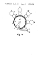
- FIG. 4 is a schematic illustration of an alternate embodiment of the present invention utilizing a cylindrical collector.
- the present invention uses separately formulated inks to print the target of a TV panel.
- the inks comprise a heat-processable, pressure-sensitive, hot melt medium mixed with a pigment.
- the preferred media are disclosed in the copending U.S. patent application Ser. No. 202,648, referred to above.
- the preferred media melt when heated above room temperature.
- the media form cohesive, pressure-sensitive, tacky films when cooled to near room temperature.
- the pigments are conventional materials used in the TV industry, namely: green, red, and blue phosphors for the colors and a black graphite for the background.
- a preferred printing device is a gravure printer as disclosed in the copending U.S. patent application Ser. No. 332,723, referred to above.
- the printing device includes: a collector, separate transfer surfaces, heated gravure surfaces, and separate supplies of melted thermoplastic, pressure-sensitive ink.
- Each heated gravure surface has a different recessed gravure pattern etched therein for receiving a corresponding ink from its separate supply. Because the gravure surface is heated, the inks remain molten while in contact therewith.
- the corresponding transfer surface formed of an elastomeric silicone material, contacts the hot fluid ink in the recessed gravure pattern. The ink splits almost evenly between the two surfaces, leaving an impression of the pattern on the transfer surface.
- the ink carried by the transfer surface immediately cools upon contact therewith, and thereby forms a cohesive, pressure-sensitive, tacky film.
- the transfer surface, carrying the tacky film is intimately contacted with the collector formed of an elastomeric silicone material. The ink transfers completely from the transfer surface to the collector.
- each separate ink pattern is printed on the collector in a specific geometric relation with each of the other ink patterns. Registration is accomplished by alignment of the components.
- the target is established. Once established, the target may be completely transferred to the panel by intimate contact of the collector with said panel.
- the complete and successive transfer of the separate ink from each transfer surface to the collector and then from the collector to the panel occurs for a number of reasons.
- the inks are tacky. They tend to stick to almost anything upon contact
- the respective surfaces are formulated so that the inks have increasing affinity for the transfer surface, the collector and the panel, respectively.
- the inks form cohesive films when cool. Thus when transfer occurs, it is complete because the film holds together. The films neither split nor tear.
- FIG. 1 is a schematic drawing exemplary of a printing device described in U.S. patent application Ser. No. 332,726 filed Dec. 21, 1981 now U.S. Pat. No. 4,440,589.
- the present invention utilizes at least four printing stations I-IV, one for each color phosphor and one for the black matrix.
- Each printing station I-IV includes a heated ink trough 18; a heated gravure roll 12 and a transfer roll 14 mounted in pairs 13 on base plate 11 by means not shown; and a doctor blade 22.
- a turret 19, mounted for rotation about a central axis C, carries collectors 16 in holders 20.
- Each collector 16 includes a flexible silicone membrane 26 secured in a frame 28.
- Each ink trough 18 carries a separate ink formulation for deposition onto a gravure roll 12 (e.g., M-black matrix, R-red, G-green, and B-blue).
- a gravure roll 12 e.g., M-black matrix, R-red, G-green, and B-blue.
- Each gravure roll 12 has a selected pattern etched therein.
- gravure roll 12 has a pattern P-M corresponding to the desired configuration of the black matrix.
- the black ink M carried in heated trough 18 is a melted graphite-filled thermoplastic fluid.
- the ink M, deposited on gravure roll 12 at station I, is doctored in a conventional manner by blade 22.
- Ink M in pattern P-M on gravure roll 12 is carried into intimate contact with transfer roll 14, whereupon the ink M is split between such rolls.
- pattern P-M is reproduced on transfer roll 14.
- the ink M deposited onto cool transfer roll 14 forms a tacky cohesive film 24-M.
- the film 24-M is brought into intimate contact with collector 16. In this instance, the ink M forming film 24-M does not split, but completely transfers from the transfer roll 14 to the collector 16.
- the pattern P-M, generated on gravure roll 12, is thereby formed on collector 16 as film 24-M'.
- the collector 16 is removed from holder 20 after receiving the composite film 24, and is locked in position within a TV panel 30 by means not shown (see FIG. 2a).
- Flexible plunger 32 engages a rear side 34 of membrane 26 and urges the membrane 26 and film 24 carried thereby against an inside surface 38 of panel 30 (see FIG. 2b).
- the film 24 preferentially adheres to the inside surface 38 of panel 30.
- the plunger 32 is withdrawn.
- the membrane 26 relaxes and peels away from the film 24, which becomes target 24' (see FIG. 2c).
- FIG. 3 an illustrative portion of target 24' is shown.
- the target 24' comprises black matrix 40 and triads 41 formed of a green dot 42G, a red dot 42R and a blue dot 42B.
- the black matrix 40 comprises the pattern P-M produced at station I using ink M.
- the dots 42R, 42G and 42B correspond respectively to the patterns P-R, P-G, and P-B printed from the respective inks R, G and B at stations II-IV.
- the target 24' is finished with an organic sealant 46 and sputtered aluminum coating 48.
- the panel 30 is thereafter fired.
- the organic materials are burned off.
- the inorganic pigments forming the black matrix and color phosphors and the aluminum coating remain.
- the collector 16 may be a fiberglass reinforced silicone blanket. Transfer of the film 24 to the panel 30 may be effected by applying pressure with a roll on the opposite side of the blanket.
- the Fiberglass helps to minimize distortion of the blanket during transfer of the Film 24 to Panel 30.
- the collector 16' may be a cylindrical roll 17 covered with an elastomer 19.
- the collector 16' receives the composite film 24 from respective paired cylindrical gravure and transfer rolls 12' and 14' located at circumferential positions or printing stations I'-IV' about the collector 16'.
- a more detailed discussion of such an arrangement is disclosed in U.S. patent application Ser. No. 173,129, filed July 28, 1980 now U.S. Pat. No. 4,445,432.
- the collector 16' has a cut 50 formed therein for allowing collector 16' to print the entire inside surface 38 of the panel 30.
- the cut 50 provides clearance between the peripheral skirt portion 31 of the mask 30 and respective leading and lagging edges 52-54 of cut 50.
- the collector 16' in FIG. 4 may print to another collector, such as the membrane collector 16 illustrated in FIGS. 1-3.
- the membrane collector 16 may then be engaged against a TV panel as set forth above.
- the target 24' produced in accordance with the teachings of the present invention may be used with a shadow-mask as described in U.S. patent application, Ser. No. 427,731, filed this same date.
- the shadow-mask is manufactured to have apertures in registration with the triads of color phosphors on the panel.
- the shadow-mask is interchangeable with various panels of similar manufacture (see Ser. No. 427,514 filed this same date).
Abstract
Description
Claims (9)
Priority Applications (5)
| Application Number | Priority Date | Filing Date | Title |
|---|---|---|---|
| US06/427,515 US4549928A (en) | 1982-09-29 | 1982-09-29 | Television panel and method of manufacture |
| CA000436531A CA1222790A (en) | 1982-09-29 | 1983-09-12 | Television tube with optional shadow mask and method of manufacture |
| DE8383305374T DE3372891D1 (en) | 1982-09-29 | 1983-09-14 | Television tube components and method of manufacture thereof |
| EP83305374A EP0104834B1 (en) | 1982-09-29 | 1983-09-14 | Television tube components and method of manufacture thereof |
| KR1019830004598A KR920001500B1 (en) | 1982-09-29 | 1983-09-29 | Television tube components and method of manufacture thereof |
Applications Claiming Priority (1)
| Application Number | Priority Date | Filing Date | Title |
|---|---|---|---|
| US06/427,515 US4549928A (en) | 1982-09-29 | 1982-09-29 | Television panel and method of manufacture |
Publications (1)
| Publication Number | Publication Date |
|---|---|
| US4549928A true US4549928A (en) | 1985-10-29 |
Family
ID=23695197
Family Applications (1)
| Application Number | Title | Priority Date | Filing Date |
|---|---|---|---|
| US06/427,515 Expired - Lifetime US4549928A (en) | 1982-09-29 | 1982-09-29 | Television panel and method of manufacture |
Country Status (1)
| Country | Link |
|---|---|
| US (1) | US4549928A (en) |
Cited By (14)
| Publication number | Priority date | Publication date | Assignee | Title |
|---|---|---|---|---|
| US4752353A (en) * | 1982-09-29 | 1988-06-21 | Corning Glass Works | Method for transfer printing of TV shadow mask resist |
| US5352634A (en) * | 1992-03-23 | 1994-10-04 | Brody Thomas P | Process for fabricating an active matrix circuit |
| WO1995012494A1 (en) * | 1993-11-03 | 1995-05-11 | Corning Incorporated | Color filter and method of printing |
| US5533447A (en) * | 1993-11-03 | 1996-07-09 | Corning Incorporated | Method and apparatus for printing a color filter ink pattern |
| US5535673A (en) * | 1993-11-03 | 1996-07-16 | Corning Incorporated | Method of printing a color filter |
| US5540147A (en) * | 1994-12-02 | 1996-07-30 | Corning Incorporated | Method for forming a contoured planarizing layer for a color filter |
| US5544582A (en) * | 1993-11-03 | 1996-08-13 | Corning Incorporated | Method for printing a color filter |
| US5624775A (en) * | 1994-02-16 | 1997-04-29 | Corning Incorporated | Apparatus and method for printing a color filter |
| US5678483A (en) * | 1994-02-16 | 1997-10-21 | Corning Incorporated | Method for printing a black border for a color filter |
| US5752442A (en) * | 1993-11-03 | 1998-05-19 | Corning Incorporated | Method for printing a color filter |
| US5972545A (en) * | 1993-11-03 | 1999-10-26 | Corning Incorporated | Method of printing a color filter |
| KR100379099B1 (en) * | 1998-10-13 | 2003-04-08 | 일렉트록스 코포레이션 | Electrostatic printing of functional toner materials for electronic manufacturing applications |
| US20090183671A1 (en) * | 2008-01-18 | 2009-07-23 | Sen-Yeu Yang | Color filter fabrication apparatus |
| US20100068385A1 (en) * | 2008-09-16 | 2010-03-18 | Fernback Katharine C | Sheet goods having a large repeat length and tile with numerous patterns |
Citations (9)
| Publication number | Priority date | Publication date | Assignee | Title |
|---|---|---|---|---|
| US2434019A (en) * | 1942-03-10 | 1948-01-06 | Joseph L Switzer | Color separation with fluorescent materials |
| US2625734A (en) * | 1950-04-28 | 1953-01-20 | Rca Corp | Art of making color-kinescopes, etc. |
| US3752072A (en) * | 1971-04-23 | 1973-08-14 | L Lorber | Process for reproducing a full-color picture in one impression |
| US3758302A (en) * | 1972-02-10 | 1973-09-11 | S Grohe | Single impression multicolor printing |
| US4263085A (en) * | 1978-06-26 | 1981-04-21 | Ellis Jon P | Tape product for forming indicia, and process and apparatus for producing same, and products produced using such tape product |
| US4379818A (en) * | 1981-12-21 | 1983-04-12 | Corning Glass Works | Artwork alignment for decorating machine |
| US4440589A (en) * | 1981-12-21 | 1984-04-03 | Corning Glass Works | Print transfer device for decorating machine |
| US4440590A (en) * | 1977-10-04 | 1984-04-03 | Letraset Corp. | Manufacture of signs |
| US4480540A (en) * | 1981-12-21 | 1984-11-06 | Corning Glass Works | Printing apparatus and method |
-
1982
- 1982-09-29 US US06/427,515 patent/US4549928A/en not_active Expired - Lifetime
Patent Citations (9)
| Publication number | Priority date | Publication date | Assignee | Title |
|---|---|---|---|---|
| US2434019A (en) * | 1942-03-10 | 1948-01-06 | Joseph L Switzer | Color separation with fluorescent materials |
| US2625734A (en) * | 1950-04-28 | 1953-01-20 | Rca Corp | Art of making color-kinescopes, etc. |
| US3752072A (en) * | 1971-04-23 | 1973-08-14 | L Lorber | Process for reproducing a full-color picture in one impression |
| US3758302A (en) * | 1972-02-10 | 1973-09-11 | S Grohe | Single impression multicolor printing |
| US4440590A (en) * | 1977-10-04 | 1984-04-03 | Letraset Corp. | Manufacture of signs |
| US4263085A (en) * | 1978-06-26 | 1981-04-21 | Ellis Jon P | Tape product for forming indicia, and process and apparatus for producing same, and products produced using such tape product |
| US4379818A (en) * | 1981-12-21 | 1983-04-12 | Corning Glass Works | Artwork alignment for decorating machine |
| US4440589A (en) * | 1981-12-21 | 1984-04-03 | Corning Glass Works | Print transfer device for decorating machine |
| US4480540A (en) * | 1981-12-21 | 1984-11-06 | Corning Glass Works | Printing apparatus and method |
Non-Patent Citations (1)
| Title |
|---|
| Garwin, IBM Technical Disclosure Bulletin, vol. 25, No. 5, Oct. 1982, p. 2598. * |
Cited By (19)
| Publication number | Priority date | Publication date | Assignee | Title |
|---|---|---|---|---|
| US4752353A (en) * | 1982-09-29 | 1988-06-21 | Corning Glass Works | Method for transfer printing of TV shadow mask resist |
| US5426074A (en) * | 1992-03-23 | 1995-06-20 | Brody; Thomas P. | Process for fabricating an active matrix circuit |
| US5352634A (en) * | 1992-03-23 | 1994-10-04 | Brody Thomas P | Process for fabricating an active matrix circuit |
| US5887522A (en) * | 1993-11-03 | 1999-03-30 | Corning Incorporated | Method for printing a color filter with radiation curable inks |
| US5701815A (en) * | 1993-11-03 | 1997-12-30 | Corning Incorporated | Method of printing a color filter |
| US5535673A (en) * | 1993-11-03 | 1996-07-16 | Corning Incorporated | Method of printing a color filter |
| US5972545A (en) * | 1993-11-03 | 1999-10-26 | Corning Incorporated | Method of printing a color filter |
| US5544582A (en) * | 1993-11-03 | 1996-08-13 | Corning Incorporated | Method for printing a color filter |
| WO1995012494A1 (en) * | 1993-11-03 | 1995-05-11 | Corning Incorporated | Color filter and method of printing |
| US5752442A (en) * | 1993-11-03 | 1998-05-19 | Corning Incorporated | Method for printing a color filter |
| US5533447A (en) * | 1993-11-03 | 1996-07-09 | Corning Incorporated | Method and apparatus for printing a color filter ink pattern |
| US5678483A (en) * | 1994-02-16 | 1997-10-21 | Corning Incorporated | Method for printing a black border for a color filter |
| US5624775A (en) * | 1994-02-16 | 1997-04-29 | Corning Incorporated | Apparatus and method for printing a color filter |
| US5540147A (en) * | 1994-12-02 | 1996-07-30 | Corning Incorporated | Method for forming a contoured planarizing layer for a color filter |
| KR100379099B1 (en) * | 1998-10-13 | 2003-04-08 | 일렉트록스 코포레이션 | Electrostatic printing of functional toner materials for electronic manufacturing applications |
| US20090183671A1 (en) * | 2008-01-18 | 2009-07-23 | Sen-Yeu Yang | Color filter fabrication apparatus |
| US20100068385A1 (en) * | 2008-09-16 | 2010-03-18 | Fernback Katharine C | Sheet goods having a large repeat length and tile with numerous patterns |
| US8496779B2 (en) * | 2008-09-16 | 2013-07-30 | Armstrong World Industries, Inc. | Sheet goods having a large repeat length and tile with numerous patterns |
| US9062464B2 (en) | 2008-09-16 | 2015-06-23 | Awi Licensing Company | Sheet goods having a large repeat length and tile with numerous patterns |
Similar Documents
| Publication | Publication Date | Title |
|---|---|---|
| US4549928A (en) | Television panel and method of manufacture | |
| US5701815A (en) | Method of printing a color filter | |
| US5887522A (en) | Method for printing a color filter with radiation curable inks | |
| US5544582A (en) | Method for printing a color filter | |
| US5533447A (en) | Method and apparatus for printing a color filter ink pattern | |
| US5678483A (en) | Method for printing a black border for a color filter | |
| US5624775A (en) | Apparatus and method for printing a color filter | |
| US5752442A (en) | Method for printing a color filter | |
| US4557798A (en) | Television tube with optional shadow mask and method of manufacture | |
| JPH0664992B2 (en) | Method for manufacturing fluorescent screen of display device | |
| EP0104834B1 (en) | Television tube components and method of manufacture thereof | |
| US4752353A (en) | Method for transfer printing of TV shadow mask resist | |
| EP0098506A3 (en) | Process and apparatus for forming permanent images using carrier supported inks containing sublimable dyes | |
| US2797172A (en) | Method of forming patterns of luminescent materials for color kinescopes | |
| JPS60225802A (en) | Production of color filter for liquid crystal | |
| JPH0664993B2 (en) | Method for forming fluorescent film of cathode ray tube | |
| JPH06118222A (en) | Formation of color filter pattern | |
| JPH04342923A (en) | Fluorescent screen forming method for fluorescent character display tube | |
| JPH0361574A (en) | Method for printing fine pattern | |
| EP0440343B1 (en) | Improvements in or relating to colour filters for liquid crystal cells | |
| JP2000238402A (en) | Printing base material, printed matter and method for highly definite printing | |
| JPH0550089B2 (en) | ||
| JPH0396385A (en) | Printing method | |
| JPH09113717A (en) | Production of color sheet and production of color display surface | |
| JPH04213402A (en) | Color filter and production thereof |
Legal Events
| Date | Code | Title | Description |
|---|---|---|---|
| AS | Assignment |
Owner name: CORNING GLASS WORKS CORNING NEW YORK A CORP OF NE Free format text: ASSIGNMENT OF ASSIGNORS INTEREST.;ASSIGNORS:BLANDING, WENDELL S.;JOHNSON, RONALD E.;VAN DE WOESTINE, ROBERT V.;REEL/FRAME:004422/0603 Effective date: 19820927 |
|
| STCF | Information on status: patent grant |
Free format text: PATENTED CASE |
|
| FPAY | Fee payment |
Year of fee payment: 4 |
|
| FPAY | Fee payment |
Year of fee payment: 8 |
|
| FEPP | Fee payment procedure |
Free format text: PAYOR NUMBER ASSIGNED (ORIGINAL EVENT CODE: ASPN); ENTITY STATUS OF PATENT OWNER: LARGE ENTITY |
|
| FPAY | Fee payment |
Year of fee payment: 12 |