US4550098A - Methods for the removal of gaseous impurities from mixed gas streams - Google Patents

Methods for the removal of gaseous impurities from mixed gas streams Download PDF

Info

Publication number
US4550098A
US4550098A US06/441,383 US44138382A US4550098A US 4550098 A US4550098 A US 4550098A US 44138382 A US44138382 A US 44138382A US 4550098 A US4550098 A US 4550098A
Authority
US
United States
Prior art keywords
oxygen
solid
potassium
hydrogen sulfide
reactive solid
Prior art date
Legal status (The legal status is an assumption and is not a legal conclusion. Google has not performed a legal analysis and makes no representation as to the accuracy of the status listed.)
Expired - Fee Related
Application number
US06/441,383
Inventor
Theodore A. Gens
Current Assignee (The listed assignees may be inaccurate. Google has not performed a legal analysis and makes no representation or warranty as to the accuracy of the list.)
Linde LLC
Original Assignee
BOC Group Inc
Priority date (The priority date is an assumption and is not a legal conclusion. Google has not performed a legal analysis and makes no representation as to the accuracy of the date listed.)
Filing date
Publication date
Application filed by BOC Group Inc filed Critical BOC Group Inc
Priority to US06/441,383 priority Critical patent/US4550098A/en
Assigned to CONTOUR SAWS, INC. reassignment CONTOUR SAWS, INC. ASSIGNMENT OF ASSIGNORS INTEREST. Assignors: GENS, THEODORE A.
Assigned to BOC GROUP THE reassignment BOC GROUP THE ASSIGNMENT OF ASSIGNORS INTEREST. Assignors: CONTOUR SAWS, INC.
Application granted granted Critical
Publication of US4550098A publication Critical patent/US4550098A/en
Anticipated expiration legal-status Critical
Expired - Fee Related legal-status Critical Current

Links

Images

Classifications

    • CCHEMISTRY; METALLURGY
    • C01INORGANIC CHEMISTRY
    • C01GCOMPOUNDS CONTAINING METALS NOT COVERED BY SUBCLASSES C01D OR C01F
    • C01G49/00Compounds of iron
    • C01G49/0018Mixed oxides or hydroxides
    • C01G49/0027Mixed oxides or hydroxides containing one alkali metal
    • BPERFORMING OPERATIONS; TRANSPORTING
    • B01PHYSICAL OR CHEMICAL PROCESSES OR APPARATUS IN GENERAL
    • B01JCHEMICAL OR PHYSICAL PROCESSES, e.g. CATALYSIS OR COLLOID CHEMISTRY; THEIR RELEVANT APPARATUS
    • B01J23/00Catalysts comprising metals or metal oxides or hydroxides, not provided for in group B01J21/00
    • B01J23/16Catalysts comprising metals or metal oxides or hydroxides, not provided for in group B01J21/00 of arsenic, antimony, bismuth, vanadium, niobium, tantalum, polonium, chromium, molybdenum, tungsten, manganese, technetium or rhenium
    • B01J23/32Manganese, technetium or rhenium
    • B01J23/34Manganese
    • BPERFORMING OPERATIONS; TRANSPORTING
    • B01PHYSICAL OR CHEMICAL PROCESSES OR APPARATUS IN GENERAL
    • B01JCHEMICAL OR PHYSICAL PROCESSES, e.g. CATALYSIS OR COLLOID CHEMISTRY; THEIR RELEVANT APPARATUS
    • B01J23/00Catalysts comprising metals or metal oxides or hydroxides, not provided for in group B01J21/00
    • B01J23/70Catalysts comprising metals or metal oxides or hydroxides, not provided for in group B01J21/00 of the iron group metals or copper
    • B01J23/76Catalysts comprising metals or metal oxides or hydroxides, not provided for in group B01J21/00 of the iron group metals or copper combined with metals, oxides or hydroxides provided for in groups B01J23/02 - B01J23/36
    • B01J23/78Catalysts comprising metals or metal oxides or hydroxides, not provided for in group B01J21/00 of the iron group metals or copper combined with metals, oxides or hydroxides provided for in groups B01J23/02 - B01J23/36 with alkali- or alkaline earth metals
    • BPERFORMING OPERATIONS; TRANSPORTING
    • B01PHYSICAL OR CHEMICAL PROCESSES OR APPARATUS IN GENERAL
    • B01JCHEMICAL OR PHYSICAL PROCESSES, e.g. CATALYSIS OR COLLOID CHEMISTRY; THEIR RELEVANT APPARATUS
    • B01J38/00Regeneration or reactivation of catalysts, in general
    • B01J38/04Gas or vapour treating; Treating by using liquids vaporisable upon contacting spent catalyst
    • B01J38/12Treating with free oxygen-containing gas
    • CCHEMISTRY; METALLURGY
    • C01INORGANIC CHEMISTRY
    • C01BNON-METALLIC ELEMENTS; COMPOUNDS THEREOF; METALLOIDS OR COMPOUNDS THEREOF NOT COVERED BY SUBCLASS C01C
    • C01B17/00Sulfur; Compounds thereof
    • C01B17/02Preparation of sulfur; Purification
    • C01B17/04Preparation of sulfur; Purification from gaseous sulfur compounds including gaseous sulfides
    • C01B17/0404Preparation of sulfur; Purification from gaseous sulfur compounds including gaseous sulfides by processes comprising a dry catalytic conversion of hydrogen sulfide-containing gases, e.g. the Claus process
    • C01B17/0426Preparation of sulfur; Purification from gaseous sulfur compounds including gaseous sulfides by processes comprising a dry catalytic conversion of hydrogen sulfide-containing gases, e.g. the Claus process characterised by the catalytic conversion
    • C01B17/0434Catalyst compositions
    • CCHEMISTRY; METALLURGY
    • C01INORGANIC CHEMISTRY
    • C01BNON-METALLIC ELEMENTS; COMPOUNDS THEREOF; METALLOIDS OR COMPOUNDS THEREOF NOT COVERED BY SUBCLASS C01C
    • C01B17/00Sulfur; Compounds thereof
    • C01B17/02Preparation of sulfur; Purification
    • C01B17/04Preparation of sulfur; Purification from gaseous sulfur compounds including gaseous sulfides
    • C01B17/0404Preparation of sulfur; Purification from gaseous sulfur compounds including gaseous sulfides by processes comprising a dry catalytic conversion of hydrogen sulfide-containing gases, e.g. the Claus process
    • C01B17/046Preparation of sulfur; Purification from gaseous sulfur compounds including gaseous sulfides by processes comprising a dry catalytic conversion of hydrogen sulfide-containing gases, e.g. the Claus process without intermediate formation of sulfur dioxide
    • C01B17/0465Catalyst compositions
    • CCHEMISTRY; METALLURGY
    • C01INORGANIC CHEMISTRY
    • C01GCOMPOUNDS CONTAINING METALS NOT COVERED BY SUBCLASSES C01D OR C01F
    • C01G3/00Compounds of copper
    • CCHEMISTRY; METALLURGY
    • C01INORGANIC CHEMISTRY
    • C01GCOMPOUNDS CONTAINING METALS NOT COVERED BY SUBCLASSES C01D OR C01F
    • C01G49/00Compounds of iron
    • C01G49/0018Mixed oxides or hydroxides
    • C01G49/0036Mixed oxides or hydroxides containing one alkaline earth metal, magnesium or lead
    • CCHEMISTRY; METALLURGY
    • C01INORGANIC CHEMISTRY
    • C01PINDEXING SCHEME RELATING TO STRUCTURAL AND PHYSICAL ASPECTS OF SOLID INORGANIC COMPOUNDS
    • C01P2006/00Physical properties of inorganic compounds
    • C01P2006/11Powder tap density
    • YGENERAL TAGGING OF NEW TECHNOLOGICAL DEVELOPMENTS; GENERAL TAGGING OF CROSS-SECTIONAL TECHNOLOGIES SPANNING OVER SEVERAL SECTIONS OF THE IPC; TECHNICAL SUBJECTS COVERED BY FORMER USPC CROSS-REFERENCE ART COLLECTIONS [XRACs] AND DIGESTS
    • Y02TECHNOLOGIES OR APPLICATIONS FOR MITIGATION OR ADAPTATION AGAINST CLIMATE CHANGE
    • Y02PCLIMATE CHANGE MITIGATION TECHNOLOGIES IN THE PRODUCTION OR PROCESSING OF GOODS
    • Y02P20/00Technologies relating to chemical industry
    • Y02P20/50Improvements relating to the production of bulk chemicals
    • Y02P20/584Recycling of catalysts

Definitions

  • the present invention relates to the use of oxidizing reactive solids for the oxidation of hydrogen sulfide gas and the removal of hydrogen sulfide and other gasses such as carbon dioxide from gas streams containing one or more of the following: hydrogen sulfide, oxygen, carbon dioxide, carbon monoxide, sulfur, hydrogen, water vapor, methane and other hydrocarbon gasses.
  • S (v) As noted in Gamson, et al., Chem. Eng. Prog. 49, 203 (1953), the term “Sulfur (v)”, hereinafter referred to as simply “S (v)”, signifies complex equilibria existing between the elemental forms of sulfur in the vapor state.
  • Reaction (1) is actually a summation of two reactions.
  • one-third of the hydrogen sulfide is oxidized to sulfur dioxide in an uncatalyzed gas-phase combustion:
  • the bed must be maintained at a sufficiently high temperature in order to prevent condensation of sulfur because difficulties, such as catalyst poisioning, are encountered in the Claus process at low temperature.
  • difficulties such as catalyst poisioning, are encountered in the Claus process at low temperature.
  • the reaction becomes thermodynamically more favorable at a lower temperature, it is desirable to carry out Reaction (3) at as low a temperature as is feasible.
  • the patent to Thompson discloses a method of oxidizing hydrogen sulfide to sulfur in the presence of oxygen over a bauxite catalyst in the temperature range from about 225° C. to about 275° C.
  • the Thompson catalyst contained about 60% alumina as well as small percentages of ferric oxide, titanium dioxide, and silica.
  • the preferred low temperatures of the Thompson disclosure would seem to suggest that Reaction (3) is controlling.
  • the catalyst at the reported temperatures displays a tendency to collect sulfur vapors which poison the catalyst.
  • Hass U.S. Pat. No. 4,171,347 discloses a method for the conversion of hydrogen sulfide directly to sulfur in the presence of oxygen and a vanadium oxide catalyst on a non-alkaline support at temperatures from about 120° C. to about 230° C.
  • the vanadium oxide catalyst appears to convert a portion of the hydrogen sulfide to sulfur dioxide.
  • the sulfur dioxide product seems to react with unreacted hydrogen sulfide, for example by Reaction (3), on the same catalyst bed, to form sulfur.
  • the patent issued to Scott discloses a cyclic process for desulfurizing hot reducing gas by contacting the gas with a desulfurizing agent, regenerating the spent desulfurizing agent, and then reusing the regenerated desulfurizing agent.
  • a bed of sintered porous pellets comprising the reaction product of manganese oxide and aluminum oxide as the desulfurizing agent is used. Regeneration of the desulfurizing agent is performed by contacting the bed of pellets with an oxidizing gaseous atmosphere.
  • the Scott process appears to result in the formation of only SO 2 , in contrast with the present invention in which little or no SO 2 is formed depending on the mode of operation.
  • Scott the temperature of the bed is maintained between about 500° C. and about 1300° C. in both the desulfurization and regeneration step.
  • reaction product to describe the porous pellets, this term apparently is not meant to indicate a chemical reaction between manganese oxide and aluminum oxide; rather, the term appears intended to describe the product produced by intimately mixing manganese oxide with aluminum oxide, forming the mixture into a pellet, and sintering, by heating the pellet.
  • ferric sulfide In the "iron-sponge" process, as discussed by Goar, Oil and Gas J. 84, 86 (1971), hydrogen sulfide is reacted with ferric oxide to form ferric sulfide. Although the bed of ferric sulfide appears to be able to be reconverted by air oxidation to ferric oxide, the bed eventually becomes saturated with sulfur solids and must be replaced.
  • the iron-sponge process is usually limited to treating gasses containing low concentrations of hydrogen sulfide, due to the economics of bed replacement. Furthermore, the sulfur removed by this process is usually lost because the "spent" bed of iron oxide is usually discarded.
  • Zinc oxide appears to be frequently used to remove hydrogen sulfide from mixed gas streams containing low concentrations of hydrogen sulfide.
  • Ammonia Part II, A. V. Slack and G. R. James, Marcel Dekker, Inc., New York, 1974, p. 338. This application resembles that of the iron-sponge process; the zinc sulfide product cannot be readily regenerated and is usually discarded after a single application.
  • the present invention relates to the use of an oxidizing reactive solid which may be used to oxidize gasses such as hydrogen sulfide and to remove hydrogen sulfide and carbon dioxide from gas streams containing one or more of the following: hydrogen sulfide, oxygen, carbon dioxide, carbon monoxide, sulfur, hydrogen, water vapor, methane and other hydrocarbon gasses.
  • gasses such as hydrogen sulfide and to remove hydrogen sulfide and carbon dioxide from gas streams containing one or more of the following: hydrogen sulfide, oxygen, carbon dioxide, carbon monoxide, sulfur, hydrogen, water vapor, methane and other hydrocarbon gasses.
  • the present invention involves the use of oxidizing reactive solids which oxidize hydrogen sulfide contained in mixed gas streams with the products being primarily sulfur and water.
  • the solids may also be used to remove carbon dioxide from mixed gas streams.
  • the oxidizing reactive solid is generally referred to as "D-M-O", wherein D is chosen from the alkali metals and alkaline earth metals comprising potassium, sodium, lithium, calcium and magnesium, M is chosen from the group comprising manganese, copper, iron, and groups VB, VIB, VIIB, VIII, and IB of the Periodic Table, Lange's Handbook of Chemistry, Twelfth Edition,; and O represents oxygen.
  • the oxidizing reactive solids used in the present invention containing active oxygen appear to react by a mechanism different from that of transition metal oxides which do not contain active oxygen.
  • the latter oxides react with hydrogen sulfide to form compounds of sulfur rather than elemental sulfur.
  • the oxidizing reactive solids of the present invention yield elemental sulfur to the extent of their active oxygen content. If such solids are contacted with gaseous hydrogen sulfide after the active oxygen content is depleted, compounds of sulfur rather than elemental sulfur will be formed.
  • a useful and advantageous characteristic of the oxidizing reactive solids used in the present invention herein is that they react readily with oxygen, thereby replenishing the active oxygen content.
  • the present invention may be either used isothermally in a catalytic mode or in a cyclic two-step mode.
  • gas streams containing hydrogen sulfide, carbon dioxide, carbon monoxide, and the like is passed over a bed containing the oxidizing reactive solid in the presence of an approximate stoichiometric amount of oxygen necessary for the conversion of hydrogen sulfide to sulfur.
  • the temperature of the bed is maintained between about 300° C. and about 700° C.
  • the lower temperature limit is constrained by the minimum temperature at which the sulfur vapors remain in the gas phase. If sulfur vapors condense on the reactive solid or in the reaction zone it is likely that increased amounts of sulfur oxides will be formed.
  • About 80% conversion of hydrogen sulfide to sulfur can be achieved throughout the identified temperature range with minimal formation of sulfur dioxide.
  • the method of the present invention can also be practiced in a two-step cyclic manner.
  • a gas stream containing hydrogen sulfide, carbon monoxide, carbon dioxide, and other gasses is passed over a bed containing the oxidizing reactive solid.
  • the solid reacts directly with the hydrogen sulfide in the gas stream to form elemental sulfur.
  • the oxidizing reactive solid is regenerated and the active oxygen replaced by flowing air or O 2 at atmospheric or higher pressure over the reactive solid at a temperature and for a period of time sufficient to regenerate the reactive solid.
  • This two-step process can be performed repeatedly, with the bed being regenerated and reacted numerous times without apparent loss of bed reactivity.
  • the D-M-O compounds display the ability to reversibly remove carbon dioxide. This property causes a partial removal of carbon dioxide from a stream of mixed gasses, when applied in a two-step cyclic process as described above.
  • Another object of the present invention is to provide a method which may be economically employed in the purification of gas streams, and more specifically in the removal of hydrogen sulfide and carbon dioxide from said gas streams.
  • FIG. 1 is a schematic illustration of the apparatus used in investigating the methods of the present invention.
  • FIG. 2 is an illustration of the rate of reaction of pure H 2 S with the K-Mn-O Compound at two different initial H 2 S pressures.
  • FIG. 3 is a graphical illustration of a typical temperature cycle showing the various features of the cycle.
  • FIG. 4 is an illustration of the extent of H 2 S conversion by the K-Mn-O compound operated in the two-step cyclic mode.
  • FIG. 5 is an illustration of the catalytic and reactive nature of the K-Mn-O compound.
  • FIG. 6 is an illustration of the extent to which the K-Mn-O compound converts hydrogen sulfide at various oxygen-hydrogen sulfide volume ratios, and at various temperatures, and the extent to which sulfur dioxide is formed.
  • FIG. 7 is an illustration of the temperature dependence of the H 2 S removal and SO 2 formation from a mixture containing 3% H 2 S by the K-Mn-O compound operated in the catalytic mode.
  • FIG. 8 is an illustration of H 2 S conversion and SO 2 formation from a mixture containing 5% H 2 S at various temperatures by the K-Mn-O compound operated in the catalytic mode.
  • FIG. 9 is an illustration of the H 2 S conversion and SO 2 formation versus space velocity by the K-Mn-O compound operated in the catalytic mode.
  • FIG. 10 is an illustration of H 2 S removal and SO 2 formation versus applied pressure of H 2 S by the K-Mn-O compound operated in the catalytic mode.
  • FIG. 11 is an illustration of the removal of pure CO 2 at various pressures by the K-Mn-O compound.
  • FIG. 12 is an illustration of the conversion of hydrogen sulfide by the K-Fe-O compound as a function of exposure time.
  • FIG. 13 is an illustration of the extent of hydrogen sulfide conversion to sulfur dioxide as a function of oxygen pressure and bed oxidation regeneration temperature of the K-Cu-O compound.
  • the present invention discloses the use of D-M-O oxidizing reactive solids which are useful for the removal of gaseous impurities, such as, for example, hydrogen sulfide, and carbon dioxide, typical of those found in the gaseous by-product of coal combustion.
  • gaseous impurities such as, for example, hydrogen sulfide, and carbon dioxide
  • the precursor of the solid in which the M component thereof, such as for example Mn, possesses a high positive valence, is heated to elevated temperatures under an inert atmosphere. In such situation, the M component is reduced to a lower positive valence.
  • An alternative procedure comprises reacting a nitrate of the M component in a strongly alkaline solution, thus oxidizing the M component of the D-M-O to a higher positive valence. Either of such procedures effectively produces the oxidizing reactive solid.
  • D-M-O solids prepared in either of the foregoing methods have a low density. These low-density solids tend to develop a resistance to the flow of gas after use. In order to alleviate this situation, it is preferred that the reactive solid be formed into pellets and that the pelletized form be used in practicing the method of the present invention.
  • the D-M-O solid may be prepared intimately mixed with a small percentage of alumina and thereafter formed into pellets. Such pellets display superior physical strength and lower alkalinity when compared to those prepared without alumina.
  • the method of present invention relating to the use of the D-M-O solid generally may be described as a method for removing the hydrogen sulfide from gas streams containing H 2 S, including those gasses formed during coal combustion. This method converts the hydrogen sulfide to sulfur, an oxidation which stops at elemental sulfur; that is, no sulfur oxides are formed.
  • the D-M-O reactive solid is easily reoxidized, such that it may be regenerated in a continuous, cyclic process.
  • the generalized chemical reactions which occur when using the D-M-O solid in the method of the present invention may be depicted as follows.
  • the D-M-O reactive solid is reduced and hydrogen sulfide is oxidized to form sulfur vapors as follows:
  • the D-M-O reactive solid is then regenerated by contacting the reduced D-M-O solid with oxygen:
  • Reaction (6) is the net reaction of Reactions (4) and (5).
  • a feed gas for example, as obtained from tanks 10 and 12 which may contain, respectively, H 2 , CO, and CO 2 in tank 10 and H 2 S in tank 12
  • the feed gas may also comprise a mixture of hydrogen sulfide, oxygen, nitrogen, or inert gas such as helium or argon.
  • the ratio of hydrogen sulfide to oxygen is adjusted to approximately that amount necessary to satisfy the stoichiometry of Reaction 1.
  • the mixture is then passed into a reactor 16 which is heated to temperatures between about 300° C. to about 700° C.
  • the space velocity of the gas flowing into the reactor may vary between about 100 to about 10000 hr -1 .
  • the gasses contact a bed (not shown) which comprises one of the D-M-O reactive solids, preferably in pelletized form, of the present invention.
  • the D-M-O reactive solid described more fully hereinafter, rapidly converts the mixture of hydrogen sulfide and oxygen to sulfur, with minimal formation of sulfur dioxide.
  • the effluent containing sulfur vapors passes out of the reactor 16 and sulfur is condensed in sulfur trap 18.
  • the effluent containing the remaining gasses is then collected in gas collector 22 for analysis by gas chromatograph 24. Excess gas may then be released through vent 28. Gasses susceptible to condensation under these conditions, such as water vapor are removed in condensate collector 20.
  • the feed gas consists of hydrogen sulfide in a carrier gas such as helium or argon, or in a mixed gas containing one or more of the following: carbon dioxide, nitrogen, hydrogen, steam and carbon monoxide.
  • the feed gas is flowed to the gas manifold 14 where it is mixed and then transferred into the reactor 16.
  • the reactor 16 is flushed with an inert gas for sufficient time so as to clear the reactor of all sulfur vapors formed during the first step which are vaporized and trapped in the sulfur trap 18.
  • the reactive solid of the present invention is then reactivated by flowing oxygen or by air from tank 26 into the reactor 16 at temperatures between about 280° C. and 600° C.
  • the K-Mn-O compound is oxidized and regenerated by flowing air containing O 2 , or by pure O 2 over the bed containing this compound:
  • This reaction sequence is indicative of the catalytic reaction with H 2 S in the presence of oxygen [O] of the reactive solid to form elemental sulfur and water.
  • the K-Mn-O reactive solid is prepared as follows: One gram-mole (158 g) of KMnO 4 is placed in a large boat centered in a tube in a horizontal tube furnace. A slow stream of argon is passed through the tube. After about 1/2 hour the temperature, measured inside the tube, is 600° C. At that point the tube is cooled to room temperature under argon atmosphere. A voluminous product (bulk volume 180 cc) is obtained, weighing 131.8 g. By assigning all the weight loss to oxygen, the composition of the product is calculated as KMnO 2 .4.
  • the K-Mn-O compound prepared as described herein is a loose powder with a bulk density as low as about 0.6 g per cc, and has the tendency to sinter and develop a noticed resistance to the flow of gas during extended use.
  • This powder form is modified to increase its density and to inhibit sintering.
  • the powder product (3 g) is loaded into a one-inch diameter cylindrical die and pressed (about 1,000 lbs. to about 2,000 lbs. of applied pressure) into discs less than 0.1 inch thick.
  • the density of the pressed material approaches about 3 g per cc.
  • the discs are embrittled by baking in air for 1/2 hour at 150° C., and broken into irregularly shaped pieces.
  • the bulk density of a bed of these pellets in the reactor 16 shown in FIG. 1 is about 0.9 g per cc.
  • K-Mn-O compound which contains alumina is as follows: One mole of KMnO 4 (158 g.) is dissolved in 1.5 liters of warm water. A solution of aluminum nitrate (0.03 moles in 0.1 liter of warm water) is added to the first solution. The combined solution is dried to a solid cake and heated to 600° C. for 1/2 hour under argon atmosphere. The alumina content is calculated at about 2% by weight. This product is crushed to a fine powder and pressed into 3/16" ⁇ 1" discs. The discs are embrittled by baking in air for 1/2 hour at 150° C., and broken into small pieces. The K-Mn-O compound is prepared in this manner to improve its resistance to crumbling and sintering and to decrease its alkalinity.
  • the reactor as shown in FIG. 1 is heated to 300° C., flushed with argon at 1 atm. and pressurized to 3.7 atm. with H 2 S. As shown in Curve A of FIG. 2, H 2 S pressure decreases rapidly showing that H 2 S is removed from the gas stream. Sulfur and water vapor are observed in the effluent.
  • the bed is then contacted with air at about 300° C. for a period of time necessary to reoxidize the K-Mn-O compound. Reoxidation is indicated by a rapid increase of about 20° C. observed in the bed temperature.
  • the bed is again contacted with H 2 S at an initial pressure of 4.3 atmospheres. Again the H 2 S pressure decreases rapidly as shown in Curve B of FIG. 2, further establishing the removal of H 2 S from the gas stream.
  • a uniform green compound of about 1 mm. thick is formed on the surface of the compressed K-Mn-O pellets during this reaction, indicative of divalent manganese, sulfur material. It appears that if the K-Mn-O compound is exposed to H 2 S in excess of its active oxygen content, the K-Mn-O compound is reduced, and forms a green manganese-sulfur material.
  • the method of the present invention in which the K-Mn-O compound is used in a two-step cyclic mode to remove dilute H 2 S from mixed gas streams, is illustrated with reference to FIG. 3.
  • the cycle depicted in FIG. 3 consists of a relatively low temperature (from about 280° to about 300° C.) H 2 S removal portion (FIG. 3, a-b), and a relatively high temperature bed reoxidation-regeneration portion (FIG. 3, c-d), in the range 500° to 600° C.
  • Argon is flushed through the system before and after the H 2 S-containing gas is contacted with the bed, in order to prevent mixing of the hydrogen sulfide gas or the product sulfur vapors with the air stream used in bed reoxidation.
  • the air flow may be continued throughout the heating and cooling portions of the cycle, or it may be introduced only briefly near the peak temperature (FIG. 3, p).
  • the rate of oxidation becomes rapid only above about 500° C., therefore, a critical variable is the peak oxidation temperature.
  • the entire effluent, points a-c, FIG. 3, is collected in gas collector 22 and analyzed by gas chromatograph 24 (FIG. 1).
  • the collection method provides for accurate measurement of the gas volumes, as well as a means of thoroughly mixing the gases to provide a uniform sample for analysis.
  • the effluent gas from the bed oxidation step, (FIG. 3, c-d) contains no sulfur or sulfur compounds as it exits the reactor.
  • the H 2 S removed from a mixed gas stream containing about of 24 vol. % CO 2 , about 73 vol. % N 2 , and about 3 vol. % H 2 S by the K-Mn-O compound operated in accordance with the cycle of FIG. 3, are shown in FIG. 4 as a function of the number of cycles. Steam was added to the extent of about 10 vol.% of the total.
  • the high activity of the K-Mn-O pellets, freshly prepared by the method of Example 1, toward H 2 S removal is reflected by the conversion of about 90 to about 100% of the hydrogen sulfide to sulfur in the first 40 cycles in FIG. 4 (no SO 2 is found throughout the run). As the run progresses, cycles 40-80, less H 2 S (about 50% of that introduced) is removed.
  • the K-Mn-O reactive compound, prepared as described in Example I acts as both a reagent as well as a catalyst in the conversion of hydrogen sulfide to sulfur. This activity is shown in FIG. 5 and described as follows.
  • a bed of K-Mn-O compound (65 g., 0.5 g-moles) placed in reactor 16 is subjected to a 50 cycle test.
  • Each cycle consists of heating the K-Mn-O solid to 610° C. in O 2 at 50 psig. and then cooling the K-Mn-O solid to 300° C. with the O 2 pressure reduced to 1 atm. It is believed that this oxidation treatment increases the K-Mn-O "active" oxygen content.
  • H 2 S (3.4%), O 2 (1%) and He (95.6%) are mixed and contacted with the reactive oxidizing solid at 300° C., and the effluent is analyzed by gas chromatography. No O 2 is found in the effluent.
  • the K-Mn-O compound (40 g) is contacted with 3% H 2 S in an inert helium carrier containing O 2 in O 2 /H 2 S vol. ratios ranging from about 0.35 to 0.65, at 300° C. and a flow rate of 160 cc/min.
  • the effluent is analyzed by gas chromatography. No O 2 is found in the effluent.
  • the amount of H 2 S found in the effluent decreases from about 1.2% to about 0.35%. In other words, the amount of H 2 S removed from the gas stream increased from about 1.8% to about 2.65%.
  • the amount of SO 2 found in the effluent increases from about 0.1% to about 0.6%.
  • raising the temperature causes an increase in the amount of H 2 S converted. No change in H 2 S conversion or SO 2 formation can be detected over a range of flow rates between 65 and 650 cm/min.
  • the O 2 /H 2 S ratio of 0.50 is chosen as the point of comparison between a series of runs at temperatures between 300° and 600° C. At each temperature, flow rates are varied from as low as 65 cc/min. to as high as about 650 cc/min. and no change in the extent of H 2 S conversion or of SO 2 formation is observed. As shown in FIG. 7, about 80% of the H 2 S is converted at 300° C. The amount of H 2 S converted is slightly increased and the amount of SO 2 formed is slightly decreased by raising the reaction temperature from about 300° C. to about 600° C. The SO 2 concentration is, in all cases, very close to one half the concentration of unconverted H 2 S.
  • the K-Mn-O is contacted with 5% H 2 S in a helium carrier and mixed with O 2 at an O 2 /H 2 S ratio of 0.5 at temperatures between about 400° C. and about 550° C. and a space velocity of about 4000 to about 4200 hr -1 .
  • the effluent gas is analyzed by gas chromatography.
  • H 2 S conversion efficiencies increase from about 40% to in excess of 60%.
  • SO 2 concentration in the effluent is approximately one-half the concentration of the unconverted H 2 S.
  • the space velocity of the influent gas (5% H 2 S, helium carrier, O 2 /H 2 S ratio of 0.5) is increased from about 4000 hr -1 up to 10,000 hr -1 between about 500° C. and about 550° C.
  • the H 2 S conversion decreases from about 60% to about 50% over this range of space velocities.
  • the SO 2 concentration is measurably less than one-half the unconverted H 2 S concentration, and O 2 is found in the effluent.
  • the sum of O 2 and SO 2 in all cases, closely approximates one-half the unconverted H 2 S. Therefore, the decrease in H 2 S conversion at higher flow rates appears to be the result of O 2 bypassing the bed of K-Mn-O pellets.
  • the ability of the K-Mn-O reactive solid to remove CO 2 from gas streams containing pure CO 2 is demonstrated as follows. Pellets of the K-Mn-O compound, prepared as described in Example I (61 g, 0.46 g-mole) are loaded into the reactor 16 shown in FIG. 1 and subjected to the following cycle: At 280° C., pressurized carbon dioxide is introduced for two minutes. The pellet bed is then heated to about 500° C. with air flowing at 1 atm. Upon cooling to about 280° C., the cycle is repeated. The CO 2 content of the effluent air is analyzed by scrubbing with standardized sodium hydroxide solution.
  • the amount of CO 2 removed increases with CO 2 pressure up to about 2 atm. and does not increase further with increased CO 2 pressure.
  • the capacity of the bed is about 0.03 g-moles CO 2 per g-mole of K-Mn-O compound at pressures above about 2 atm. At 1 atm. of applied CO 2 pressure, about 0.017 moles of CO 2 are removed per mole of K-Mn-O compound. No change in this capacity is observed if this cycle is repeated for 79 cycles.
  • the K-Mn-O reactive solid containing alumina as prepared in Example II removes carbon dioxide from mixed gas streams containing carbon dioxide and nitrogen as follows.
  • the reactor 16, shown in FIG. 1, is loaded with 59 g of the pelletized K-Mn-O compound containing alumina and subjected to the following cycle.
  • the reactor is flushed with argon and the K-Mn-O compound is contacted with 25% CO 2 in N 2 at 50 psig and a space velocity of about 1000 hr -1 at about 290° C.
  • the reactor is flushed with argon at 50 psig.
  • the reactor was then heated to 585° C. with flowing air at 50 psig. Air flow is continued as the reactor cools to about 300° C., and the cycle is repeated.
  • K-Fe-O compound a reactive compound containing potassium, iron and oxygen
  • the K-Fe-O reactive solid may be regenerated by flowing oxygen or air over the reduced K-Fe-O solids, as shown in the following reaction:
  • [O] designates the active oxygen provided by the K-Fe-O compound.
  • Preparation of the reactive solid containing potassium, iron, and oxygen proceeds as follows: ferric nitrate hydrate, Fe(NO 3 ) 3 .9H 2 O (172 g, 0.43 gram-moles), is added with stirring to 300 grams of melted KOH. The resultant mixture is heated to slightly above 360° C. The green melt is cooled, broken up, and stirred into 500 ml of cold 50% potassium hydroxide solution. An insoluble brown precipitate is recovered by filtration. The precipitate is reslurried once in cold 1M KOH and refiltered. The filter cake is dried at 100° C. in a nitrogen atmosphere. The recovered dry product weighs 100 grams. The dry product is pelletized by the method of Example I.
  • the method of the present invention in which the K-Fe-O compound, prepared as described in Example X, is used in a two-step cyclic mode, is illustrated in this example.
  • Pellets weighing 37 g, are placed in reactor 16 of FIG. 1 and subjected to six cycles in which they are heated to about 620° C. in flowing He, then oxidized 1 hour at about 650° C. at about 80 psig of oxygen and cooled to room temperature under 1 atm of oxygen.
  • About 40 cc (measured at standard temperature and pressure) of oxygen is evolved during heating to about 650° C. with the major fraction evolved above 400° C.
  • the K-Fe-O compound is oxidized for about 15 hours under 80 psig of oxygen, the total O 2 evolution increases to about 60 cc.
  • the bed of K-Fe-O pellets is subjected to four cycles in which it is contacted with a stream of 1.1% H 2 S diluted with a helium carrier followed by oxidation and regeneration.
  • the results of the fifth such cycle is shown in FIG. 12.
  • the K-Fe-O was first reoxidized in 1 atm O 2 at 288° C. for 20 minutes. A 14° C. temperature rise in the bed occurs during the first minute of reoxidation. Reoxidation is completed over the next 15 hours at 500° C. under 1 atm O 2 , and the reactor is cooled to about 290° C.
  • a stream of 1.1% H 2 S in He is contacted with the bed at a space velocity of 1200 hr -1 .
  • the K-Fe-O prepared as described in Example X reacts as a catalyst in the conversion of H 2 S to sulfur in the presence of O 2 .
  • the K-Fe-O bed of pellets (37 g) is subjected at 290° C. to a mixed gas stream containing from about 2.4 to about 2.6 vol. % H 2 S, and 1.9 vol. % O 2 in a helium carrier at a space velocity of 1200 hr -1 .
  • the run is continued until steady state is reached as judged by the composition of the product gasses.
  • the effluent gas is analyzed by gas chromatography. Additional runs are made in a similar manner and are summarized in Table 1.
  • the results in Table 1 indicate, from the large values of sulfur relative to SO 2 , that reaction (1) is the major reaction.
  • the O 2 /H 2 S volume ratio decreases, the amount of SO 2 formed and the amount of H 2 S reacted both decrease.
  • K-Cu-O compound a reactive solid containing potassium, copper and oxygen
  • the K-Cu-O reactive solid is made as follows. Copper nitrate hydrate (150 g. 0.645 moles) is dissolved in 200 ml. of water. A solution of 280 grams of potassium hydroxide in 280 ml. of water is added with stirring. Chopped ice is placed in the solution to prevent dehydration of the gelatinous copper hydroxide product. The supernatant liquid is decanted and the gelatinous product is filtered and air dried. The moist gel is pressed into pellets about 0.2" thick and 1" diameter at about 2000 psig. The pellets are dried at 150° C. for one hour and then broken into small pieces. The pellets are baked at 500° C. for one hour in a carbon dioxide atmosphere to decompose residual nitrate and to convert free potassium hydroxide to carbonate. The recovered product weighs 65 grams and has a bulk volume of 70 cc.
  • a bed of K-Cu-O compound (35 grams), prepared as described in Example XIII, is subjected to an 850 cc/min. flow of 3% H 2 S in He for 1 min. at 283° C., then heated to a temperature of between 360° C. and about 500° C. for oxidation and regeneration in the presence of pressurized O 2 in a repetitive cycle similar to that depicted in FIG. 3.
  • the pressurized O 2 is introduced for a 3 minute period which encompasses the peak oxidation temperature.
  • H 2 S is completely converted to a mixture of sulfur or SO 2 .
  • the amount of H 2 S converted to either sulfur or SO 2 depends upon the oxidation temperature and applied oxygen pressure. When the oxidation temperature is about 360° C., and 5 psig. O 2 is applied, only SO 2 , and no sulfur, is found in the effluent stream. When the regeneration temperature is increased to 500° C. with application of 22 psig. O 2 , only 2% of the H 2 S is converted to SO 2 and 98% is converted to sulfur. Higher temperatures above about 500° C. cannot be used in the regeneration of the K-Cu-O reactive compound because the pelletized bed tends to develop resistance to gas flow.
  • the K-Cu-O compound resembles the K-Mn-O and K-Fe-O compounds previously discussed, and its ability to convert H 2 S to sulfur depends upon the extent that it contains active oxygen obtained during the regeneration step. It differs from the K-Fe-O and K-Mn-O compounds in that it continues to react rapidly with H 2 S after its active oxygen content is depleted, in this case forming SO 2 , and not sulfur, as the product.
  • thermodynamics of the one-step formation of sulfur from hydrogen sulfide according to Reaction (1) are very favorable, and therefore quantitative conversion of H 2 S by this reaction, involving the alkaline metal oxide, might be predicted.
  • Reaction (1) is carried out on large industrial scale in the Claus process. In the Claus process, Reaction (1) is a combination of Reactions (2) and (3), set forth previously. The thermodynamics of Reaction (3) are less favorable than those of either Reaction (2) or Reaction (1). Because of this, the less favorable thermodynamics of Reaction (3) control the efficiencies of the Claus process.
  • conversion of H 2 S to sulfur through the use of the D-M-O compound does not involve intermediate Reactions (2) and (3) and therefore is not affected by the less-favorable thermodynamics of Reaction (3).
  • the quantitative conversion of H 2 S within the limits of detection, as observed in Example IV could not be accomplished under the same pressure and temperature conditions in the Claus process.
  • the Claus process also makes use of a solid catalyst, the mechanistic path must differ from that operative on the D-M-O compound in the catalysis of Reaction (1). This difference in mechanistic path might be expected, considering that the reactivity of the D-M-O compound toward hydrogen sulfide depends upon its capability for reaction with oxygen, a capability not present in the Claus process catalyst.

Abstract

Methods are disclosed for the purification of mixed gas streams containing hydrogen sulfide, carbon dioxide, carbon monoxide, sulfur, hydrogen, and methane and other hydrocarbon gases, and mixtures thereof, by the use of an oxidizing reactive solid. In one method, the oxidizing reactive solid is, in a first step, contacted with the mixed gas stream which may contain, among other gases, hydrogen sulfide and carbon dioxide. The reactive solid removes the hydrogen sulfide in the form of elemental sulfur with no detectable formation of sulfur oxide. The reactive solid also partially removes the carbon dioxide from the mixed gas stream. In the second step of the first method, the oxidizing reactive solid is regenerated by flowing air. In a second method of the present invention, mixed gas streams, containing hydrogen sulfide and oxygen in an approximate stoichiometric amount, are contacted with the solid, and hydrogen sulfide is converted directly to sulfur with minimal formation of compounds of sulfur. The oxidizing reactive solid has the general formula D-M-O, wherein D is chosen from the alkali metals or alkaline earth metals comprising sodium, potassium, lithium, calcium or magnesium; M represents a transition metal selected from the group comprising manganese, copper, and iron, and groups IB, VB, VIB, VIIB or VIII from the Periodic Table; and O designates oxygen.

Description

BACKGROUND OF THE INVENTION
1. Field of the Invention
The present invention relates to the use of oxidizing reactive solids for the oxidation of hydrogen sulfide gas and the removal of hydrogen sulfide and other gasses such as carbon dioxide from gas streams containing one or more of the following: hydrogen sulfide, oxygen, carbon dioxide, carbon monoxide, sulfur, hydrogen, water vapor, methane and other hydrocarbon gasses.
2. Description of the Prior Art
Removal of oxidizable impurities such as hydrogen sulfide alone or in the presence of other gasses in the absence or in the presence of high temperature oxidation catalyst has been the subject of extensive research because of the desirability of purifying such mixed gas streams for environmental and other reasons.
As discussed by Gamson and Elkins [Chem. Eng. Prog. 49, 203-15 (1953)], a widely used commercial process for removal of hydrogen sulfide from gas streams is the Claus process. The original Claus process has evolved through several modifications and improvements, but the basic chemical reactions remain unchanged. The overall result of the Claus process is the conversion of hydrogen sulfide to sulfur:
H.sub.2 S+1/2O.sub.2 →H.sub.2 O+Sulfur(v)           (1)
As noted in Gamson, et al., Chem. Eng. Prog. 49, 203 (1953), the term "Sulfur (v)", hereinafter referred to as simply "S (v)", signifies complex equilibria existing between the elemental forms of sulfur in the vapor state.
In practice Reaction (1) is actually a summation of two reactions. In the first reaction, one-third of the hydrogen sulfide is oxidized to sulfur dioxide in an uncatalyzed gas-phase combustion:
1/3H.sub.2 S+1/2O.sub.2 →1/3H.sub.2 O+1/3SO.sub.2   ( 2)
The products of Reaction (2), along with the remaining two-thirds of the hydrogen sulfide, are reacted over a bed of bauxite or alumina catalyst at about 200° C. to 400° C.:
2/3H.sub.2 S+1/3SO.sub.2 →2/3H.sub.2 O+S(v)         (3)
The bed must be maintained at a sufficiently high temperature in order to prevent condensation of sulfur because difficulties, such as catalyst poisioning, are encountered in the Claus process at low temperature. On the other hand, because the reaction becomes thermodynamically more favorable at a lower temperature, it is desirable to carry out Reaction (3) at as low a temperature as is feasible.
Attempts have been made to carry out direct oxidation of hydrogen sulfide to sulfur by Reaction (1), thereby avoiding the thermodynamic limitations imposed by Reaction (3). An example of this process is disclosed by Baehr, et. al. (U.S. Pat. No. 2,200,529). That patent purports to disclose a converson of a large fraction of hydrogen sulfide directly to sulfur in a free flame in the presence of the stoichiometric amount of oxygen.
Gamson (U.S. Pat. No. 2,594,149) noted that Reaction (1) becomes the principal reaction at very high temperatures. That patent discloses a process for converting hydrogen sulfide directly to sulfur in yields of about 75% at temperatures above about 1300° C., followed by a rapid cooling of the product gasses to minimize formation of sulfur dioxide by reaction of residual oxygen and sulfur product. Gamson also discloses that the oxidation of hydrogen sulfide does not appear to proceed at a practical rate at temperatures below about 500° C. in the absence of catalysts. The patent to Gamson does not disclose a catalytic, low temperature conversion of the type disclosed in the present invention.
An article by Grekel, Oil and Gas Journal Vol. 57, 76-79 (1959), discloses a method for the direct oxidation of hydrogen sulfide to sulfur in the presence of bauxite at temperatures between about 200° C. and about 800° C. Grekel states that, at low space velocities, lower temperatures are preferred, inferring that Reaction (3) is involved. Grekel further implies that at higher space velocities, Reaction (3) becomes less important.
The patent to Thompson (U.S. Pat. No. 1,922,872) discloses a method of oxidizing hydrogen sulfide to sulfur in the presence of oxygen over a bauxite catalyst in the temperature range from about 225° C. to about 275° C. The Thompson catalyst contained about 60% alumina as well as small percentages of ferric oxide, titanium dioxide, and silica. The preferred low temperatures of the Thompson disclosure would seem to suggest that Reaction (3) is controlling. However, the catalyst at the reported temperatures displays a tendency to collect sulfur vapors which poison the catalyst.
Hass (U.S. Pat. No. 4,171,347) discloses a method for the conversion of hydrogen sulfide directly to sulfur in the presence of oxygen and a vanadium oxide catalyst on a non-alkaline support at temperatures from about 120° C. to about 230° C. The vanadium oxide catalyst appears to convert a portion of the hydrogen sulfide to sulfur dioxide. The sulfur dioxide product seems to react with unreacted hydrogen sulfide, for example by Reaction (3), on the same catalyst bed, to form sulfur.
The patent issued to Scott (U.S. Pat. No. 4,164,544) discloses a cyclic process for desulfurizing hot reducing gas by contacting the gas with a desulfurizing agent, regenerating the spent desulfurizing agent, and then reusing the regenerated desulfurizing agent. As disclosed in Scott, a bed of sintered porous pellets comprising the reaction product of manganese oxide and aluminum oxide as the desulfurizing agent is used. Regeneration of the desulfurizing agent is performed by contacting the bed of pellets with an oxidizing gaseous atmosphere. The Scott process appears to result in the formation of only SO2, in contrast with the present invention in which little or no SO2 is formed depending on the mode of operation. In Scott, the temperature of the bed is maintained between about 500° C. and about 1300° C. in both the desulfurization and regeneration step. Although Scott uses the term "reaction product" to describe the porous pellets, this term apparently is not meant to indicate a chemical reaction between manganese oxide and aluminum oxide; rather, the term appears intended to describe the product produced by intimately mixing manganese oxide with aluminum oxide, forming the mixture into a pellet, and sintering, by heating the pellet.
In the "iron-sponge" process, as discussed by Goar, Oil and Gas J. 84, 86 (1971), hydrogen sulfide is reacted with ferric oxide to form ferric sulfide. Although the bed of ferric sulfide appears to be able to be reconverted by air oxidation to ferric oxide, the bed eventually becomes saturated with sulfur solids and must be replaced. The iron-sponge process is usually limited to treating gasses containing low concentrations of hydrogen sulfide, due to the economics of bed replacement. Furthermore, the sulfur removed by this process is usually lost because the "spent" bed of iron oxide is usually discarded.
Zinc oxide appears to be frequently used to remove hydrogen sulfide from mixed gas streams containing low concentrations of hydrogen sulfide. ("Ammonia" Part II, A. V. Slack and G. R. James, Marcel Dekker, Inc., New York, 1974, p. 338). This application resembles that of the iron-sponge process; the zinc sulfide product cannot be readily regenerated and is usually discarded after a single application.
The patent to Weiss (U.S. Pat. No. 1,971,168) discloses the preparation of oxidation catalysts represented by the general formula M(HMnO3)2 and M(MnO3) wherein the symbol M represents one of various possible metals capable of forming the catalyst in association with manganese. These metals, termed acid manganites, were shown to be useful in the oxidation of carbon monoxide to carbon dioxides. The Weiss patent does not disclose removal of any impurity other than carbon monoxide from a mixed gas stream.
The U.S. patent issued to Haacke (U.S. Pat. No. 3,914,389) discloses a compound having the empirical formula LaCu0.5 Mn0.5 O3 as an oxidation catalyst to convert carbon monoxide to carbon dioxide in automobile exhaust systems.
The patent issued to Remeika et al. (U.S. Pat. No. 4,001,371) discloses a catalyst of the formula La0.8 K0.2 MnO3 to catalyze the conversion of NOx pollutants to materials N2 O, N2, and oxygen. This catalyst is also said to be effective for promoting reactions such as the oxidation of carbon monoxide to carbon dioxide. Each of the catalysts disclosed in the Remeika patent requires the presence of at least one rare earth element, i.e., La, Pr, and Nd, as a component.
None of the above descriptions or disclosures disclose the methods of the present invention in which a reactive solid is used for removing impurities such as hydrogen sulfide and carbon dioxide from gas mixtures.
SUMMARY OF THE INVENTION
The present invention relates to the use of an oxidizing reactive solid which may be used to oxidize gasses such as hydrogen sulfide and to remove hydrogen sulfide and carbon dioxide from gas streams containing one or more of the following: hydrogen sulfide, oxygen, carbon dioxide, carbon monoxide, sulfur, hydrogen, water vapor, methane and other hydrocarbon gasses.
As discussed more fully hereinafter, the present invention involves the use of oxidizing reactive solids which oxidize hydrogen sulfide contained in mixed gas streams with the products being primarily sulfur and water. The solids may also be used to remove carbon dioxide from mixed gas streams.
For the purposes of this disclosure, the oxidizing reactive solid is generally referred to as "D-M-O", wherein D is chosen from the alkali metals and alkaline earth metals comprising potassium, sodium, lithium, calcium and magnesium, M is chosen from the group comprising manganese, copper, iron, and groups VB, VIB, VIIB, VIII, and IB of the Periodic Table, Lange's Handbook of Chemistry, Twelfth Edition,; and O represents oxygen.
In the present invention, it has been discovered that a portion of the oxygen in the D-M-O reactive solid reacts readily with gaseous hydrogen sulfide to yield as products only sulfur and water. This oxygen, hereinafter referred to as "active oxygen", may be readily introduced into the D-M-O reactive solid.
The oxidizing reactive solids used in the present invention containing active oxygen appear to react by a mechanism different from that of transition metal oxides which do not contain active oxygen. The latter oxides react with hydrogen sulfide to form compounds of sulfur rather than elemental sulfur. The oxidizing reactive solids of the present invention yield elemental sulfur to the extent of their active oxygen content. If such solids are contacted with gaseous hydrogen sulfide after the active oxygen content is depleted, compounds of sulfur rather than elemental sulfur will be formed.
A useful and advantageous characteristic of the oxidizing reactive solids used in the present invention herein is that they react readily with oxygen, thereby replenishing the active oxygen content.
The present invention may be either used isothermally in a catalytic mode or in a cyclic two-step mode. In the catalytic mode, gas streams containing hydrogen sulfide, carbon dioxide, carbon monoxide, and the like is passed over a bed containing the oxidizing reactive solid in the presence of an approximate stoichiometric amount of oxygen necessary for the conversion of hydrogen sulfide to sulfur. The temperature of the bed is maintained between about 300° C. and about 700° C. The lower temperature limit is constrained by the minimum temperature at which the sulfur vapors remain in the gas phase. If sulfur vapors condense on the reactive solid or in the reaction zone it is likely that increased amounts of sulfur oxides will be formed. About 80% conversion of hydrogen sulfide to sulfur can be achieved throughout the identified temperature range with minimal formation of sulfur dioxide.
As noted, the method of the present invention can also be practiced in a two-step cyclic manner. In the first step, a gas stream containing hydrogen sulfide, carbon monoxide, carbon dioxide, and other gasses is passed over a bed containing the oxidizing reactive solid. In this step, the solid reacts directly with the hydrogen sulfide in the gas stream to form elemental sulfur. In the second step, the oxidizing reactive solid is regenerated and the active oxygen replaced by flowing air or O2 at atmospheric or higher pressure over the reactive solid at a temperature and for a period of time sufficient to regenerate the reactive solid. This two-step process can be performed repeatedly, with the bed being regenerated and reacted numerous times without apparent loss of bed reactivity.
The D-M-O compounds display the ability to reversibly remove carbon dioxide. This property causes a partial removal of carbon dioxide from a stream of mixed gasses, when applied in a two-step cyclic process as described above.
It is thus an object of this invention to facilitate the direct oxidation of hydrogen sulfide to sulfur through the use of an approximate stoichiometric amount of oxygen and in the presence of the oxidizing reactive solid according to the following reaction:
H.sub.2 S+1/2O.sub.2 →H.sub.2 O+S(v)
It is a further object of this invention to facilitate the above reaction either by catalytic or direct chemical reaction.
It is yet a further object of this invention to remove CO2, H2 S, and S gasses from gas streams.
It is a further object of this invention to remove hydrogen sulfide from mixed gas streams using a process in which the bed of the oxidizing reactive solid is reacted by contact with the gas stream, followed by regeneration of the oxidizing reactive solid; a process which may be performed numerous times without significant loss of reactivity of the reactive solid.
It is a further object of this invention to use the reactive solid in a method for the removal of carbon dioxide from mixed gas streams.
Another object of the present invention is to provide a method which may be economically employed in the purification of gas streams, and more specifically in the removal of hydrogen sulfide and carbon dioxide from said gas streams.
These and other objects and advantages of the present invention will become apparent with reference to the drawings and the detailed description of the invention which follow hereinafter.
BRIEF DESCRIPTION OF THE DRAWINGS
FIG. 1 is a schematic illustration of the apparatus used in investigating the methods of the present invention.
FIG. 2 is an illustration of the rate of reaction of pure H2 S with the K-Mn-O Compound at two different initial H2 S pressures.
FIG. 3 is a graphical illustration of a typical temperature cycle showing the various features of the cycle.
FIG. 4 is an illustration of the extent of H2 S conversion by the K-Mn-O compound operated in the two-step cyclic mode.
FIG. 5 is an illustration of the catalytic and reactive nature of the K-Mn-O compound.
FIG. 6 is an illustration of the extent to which the K-Mn-O compound converts hydrogen sulfide at various oxygen-hydrogen sulfide volume ratios, and at various temperatures, and the extent to which sulfur dioxide is formed.
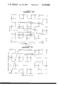
FIG. 7 is an illustration of the temperature dependence of the H2 S removal and SO2 formation from a mixture containing 3% H2 S by the K-Mn-O compound operated in the catalytic mode.
FIG. 8 is an illustration of H2 S conversion and SO2 formation from a mixture containing 5% H2 S at various temperatures by the K-Mn-O compound operated in the catalytic mode.
FIG. 9 is an illustration of the H2 S conversion and SO2 formation versus space velocity by the K-Mn-O compound operated in the catalytic mode.
FIG. 10 is an illustration of H2 S removal and SO2 formation versus applied pressure of H2 S by the K-Mn-O compound operated in the catalytic mode.
FIG. 11 is an illustration of the removal of pure CO2 at various pressures by the K-Mn-O compound.
FIG. 12 is an illustration of the conversion of hydrogen sulfide by the K-Fe-O compound as a function of exposure time.
FIG. 13 is an illustration of the extent of hydrogen sulfide conversion to sulfur dioxide as a function of oxygen pressure and bed oxidation regeneration temperature of the K-Cu-O compound.
DETAILED DESCRIPTION
The present invention discloses the use of D-M-O oxidizing reactive solids which are useful for the removal of gaseous impurities, such as, for example, hydrogen sulfide, and carbon dioxide, typical of those found in the gaseous by-product of coal combustion.
In forming the D-M-O solid, the precursor of the solid, in which the M component thereof, such as for example Mn, possesses a high positive valence, is heated to elevated temperatures under an inert atmosphere. In such situation, the M component is reduced to a lower positive valence. An alternative procedure comprises reacting a nitrate of the M component in a strongly alkaline solution, thus oxidizing the M component of the D-M-O to a higher positive valence. Either of such procedures effectively produces the oxidizing reactive solid.
D-M-O solids prepared in either of the foregoing methods have a low density. These low-density solids tend to develop a resistance to the flow of gas after use. In order to alleviate this situation, it is preferred that the reactive solid be formed into pellets and that the pelletized form be used in practicing the method of the present invention.
Alternatively, as described hereinafter, the D-M-O solid may be prepared intimately mixed with a small percentage of alumina and thereafter formed into pellets. Such pellets display superior physical strength and lower alkalinity when compared to those prepared without alumina.
The method of present invention relating to the use of the D-M-O solid generally may be described as a method for removing the hydrogen sulfide from gas streams containing H2 S, including those gasses formed during coal combustion. This method converts the hydrogen sulfide to sulfur, an oxidation which stops at elemental sulfur; that is, no sulfur oxides are formed.
The D-M-O reactive solid is easily reoxidized, such that it may be regenerated in a continuous, cyclic process.
The generalized chemical reactions which occur when using the D-M-O solid in the method of the present invention may be depicted as follows. The D-M-O reactive solid is reduced and hydrogen sulfide is oxidized to form sulfur vapors as follows:
D-M-O.sub.x+y +YH.sub.2 S→D-M-O.sub.x +YH.sub.2 O+YS(v) (4)
The D-M-O reactive solid is then regenerated by contacting the reduced D-M-O solid with oxygen:
D-M-O.sub.x +Y/2O.sub.2 →D-M-O.sub.x+y              (5)
The oxygen, when incorporated in the reactive solid, is active in the desired reaction:
[O]+H.sub.2 S→H.sub.2 O+S(v)                        (6)
where [O] designates the active oxygen fixed in the reactive solid by Reaction (5). Thus, Reaction (6) is the net reaction of Reactions (4) and (5).
The two methods of practicing the present invention may be best understood with reference to FIG. 1. In the catalytic mode, a feed gas (for example, as obtained from tanks 10 and 12 which may contain, respectively, H2, CO, and CO2 in tank 10 and H2 S in tank 12) is mixed in a gas manifold 14. The feed gas may also comprise a mixture of hydrogen sulfide, oxygen, nitrogen, or inert gas such as helium or argon. The ratio of hydrogen sulfide to oxygen is adjusted to approximately that amount necessary to satisfy the stoichiometry of Reaction 1. The mixture is then passed into a reactor 16 which is heated to temperatures between about 300° C. to about 700° C. The space velocity of the gas flowing into the reactor may vary between about 100 to about 10000 hr-1. In the reactor 16, the gasses contact a bed (not shown) which comprises one of the D-M-O reactive solids, preferably in pelletized form, of the present invention. The D-M-O reactive solid, described more fully hereinafter, rapidly converts the mixture of hydrogen sulfide and oxygen to sulfur, with minimal formation of sulfur dioxide. The effluent containing sulfur vapors passes out of the reactor 16 and sulfur is condensed in sulfur trap 18. The effluent containing the remaining gasses is then collected in gas collector 22 for analysis by gas chromatograph 24. Excess gas may then be released through vent 28. Gasses susceptible to condensation under these conditions, such as water vapor are removed in condensate collector 20.
In the two-step process of the present invention, the feed gas consists of hydrogen sulfide in a carrier gas such as helium or argon, or in a mixed gas containing one or more of the following: carbon dioxide, nitrogen, hydrogen, steam and carbon monoxide. The feed gas is flowed to the gas manifold 14 where it is mixed and then transferred into the reactor 16. After the hydrogen sulfide has reacted with the reactive D-M-O solid, the reactor 16 is flushed with an inert gas for sufficient time so as to clear the reactor of all sulfur vapors formed during the first step which are vaporized and trapped in the sulfur trap 18. The reactive solid of the present invention is then reactivated by flowing oxygen or by air from tank 26 into the reactor 16 at temperatures between about 280° C. and 600° C.
In order to more fully understand the present invention, a series of examples will be given. However, in order to appreciate these examples, and the advantageous properties displayed by the D-M-O solid in the method of the present invention, it is first necessary to summarize the chemical reaction mechanisms thought to occur when the D-M-O solid is used. In order to do so, particular reference to the reactive solid containing potassium, manganese and oxygen (hereinafter "K-Mn-O") will be made. It should be appreciated that the following mechanisms are believed, based on experimental data, to occur. Thus, they are presented not by way of limitation.
In the reaction of the K-Mn-O compound with H2 S, the K-Mn-O compound is reduced and hydrogen sulfide is oxidized to elemental Sulfur as follows:
KMnO.sub.x+y +YH.sub.2 S→KMnO.sub.x +YH.sub.2 O+YS  (7)
The K-Mn-O compound is oxidized and regenerated by flowing air containing O2, or by pure O2 over the bed containing this compound:
KMnO.sub.x +Y/2O.sub.2 →KMnO.sub.x+y                (8)
With the net reaction:
YH.sub.2 S+Y[O]→YH.sub.2 O+YS(v)                    (9)
This reaction sequence is indicative of the catalytic reaction with H2 S in the presence of oxygen [O] of the reactive solid to form elemental sulfur and water.
The preparation of the reactive solid containing potassium, manganese and oxygen and the use of the solid so produced in the method of the invention are described in the following examples.
EXAMPLE I
The K-Mn-O reactive solid is prepared as follows: One gram-mole (158 g) of KMnO4 is placed in a large boat centered in a tube in a horizontal tube furnace. A slow stream of argon is passed through the tube. After about 1/2 hour the temperature, measured inside the tube, is 600° C. At that point the tube is cooled to room temperature under argon atmosphere. A voluminous product (bulk volume 180 cc) is obtained, weighing 131.8 g. By assigning all the weight loss to oxygen, the composition of the product is calculated as KMnO2.4.
The K-Mn-O compound prepared as described herein is a loose powder with a bulk density as low as about 0.6 g per cc, and has the tendency to sinter and develop a noticed resistance to the flow of gas during extended use.
This powder form is modified to increase its density and to inhibit sintering. The powder product (3 g) is loaded into a one-inch diameter cylindrical die and pressed (about 1,000 lbs. to about 2,000 lbs. of applied pressure) into discs less than 0.1 inch thick. The density of the pressed material approaches about 3 g per cc. The discs are embrittled by baking in air for 1/2 hour at 150° C., and broken into irregularly shaped pieces. The bulk density of a bed of these pellets in the reactor 16 shown in FIG. 1 is about 0.9 g per cc.
EXAMPLE II
An alternative preparation of the K-Mn-O compound which contains alumina is as follows: One mole of KMnO4 (158 g.) is dissolved in 1.5 liters of warm water. A solution of aluminum nitrate (0.03 moles in 0.1 liter of warm water) is added to the first solution. The combined solution is dried to a solid cake and heated to 600° C. for 1/2 hour under argon atmosphere. The alumina content is calculated at about 2% by weight. This product is crushed to a fine powder and pressed into 3/16"×1" discs. The discs are embrittled by baking in air for 1/2 hour at 150° C., and broken into small pieces. The K-Mn-O compound is prepared in this manner to improve its resistance to crumbling and sintering and to decrease its alkalinity.
EXAMPLE III
In order to establish the oxidizing ability of the K-Mn-O compound to H2 S, the following test is performed. The K-Mn-O compound prepared as described in Example I and reacted with carbon dioxide for about 80 cycles as described in Example VIII is loaded into the reactor 16 of FIG. 1.
The reactor as shown in FIG. 1 is heated to 300° C., flushed with argon at 1 atm. and pressurized to 3.7 atm. with H2 S. As shown in Curve A of FIG. 2, H2 S pressure decreases rapidly showing that H2 S is removed from the gas stream. Sulfur and water vapor are observed in the effluent.
The bed is then contacted with air at about 300° C. for a period of time necessary to reoxidize the K-Mn-O compound. Reoxidation is indicated by a rapid increase of about 20° C. observed in the bed temperature.
After reoxidation, the bed is again contacted with H2 S at an initial pressure of 4.3 atmospheres. Again the H2 S pressure decreases rapidly as shown in Curve B of FIG. 2, further establishing the removal of H2 S from the gas stream. A uniform green compound of about 1 mm. thick is formed on the surface of the compressed K-Mn-O pellets during this reaction, indicative of divalent manganese, sulfur material. It appears that if the K-Mn-O compound is exposed to H2 S in excess of its active oxygen content, the K-Mn-O compound is reduced, and forms a green manganese-sulfur material.
EXAMPLE IV
The method of the present invention, in which the K-Mn-O compound is used in a two-step cyclic mode to remove dilute H2 S from mixed gas streams, is illustrated with reference to FIG. 3. The cycle depicted in FIG. 3 consists of a relatively low temperature (from about 280° to about 300° C.) H2 S removal portion (FIG. 3, a-b), and a relatively high temperature bed reoxidation-regeneration portion (FIG. 3, c-d), in the range 500° to 600° C. Argon is flushed through the system before and after the H2 S-containing gas is contacted with the bed, in order to prevent mixing of the hydrogen sulfide gas or the product sulfur vapors with the air stream used in bed reoxidation. The air flow may be continued throughout the heating and cooling portions of the cycle, or it may be introduced only briefly near the peak temperature (FIG. 3, p). The rate of oxidation becomes rapid only above about 500° C., therefore, a critical variable is the peak oxidation temperature.
The entire effluent, points a-c, FIG. 3, is collected in gas collector 22 and analyzed by gas chromatograph 24 (FIG. 1). The collection method provides for accurate measurement of the gas volumes, as well as a means of thoroughly mixing the gases to provide a uniform sample for analysis. The effluent gas from the bed oxidation step, (FIG. 3, c-d) contains no sulfur or sulfur compounds as it exits the reactor.
The H2 S removed from a mixed gas stream containing about of 24 vol. % CO2, about 73 vol. % N2, and about 3 vol. % H2 S by the K-Mn-O compound operated in accordance with the cycle of FIG. 3, are shown in FIG. 4 as a function of the number of cycles. Steam was added to the extent of about 10 vol.% of the total. The high activity of the K-Mn-O pellets, freshly prepared by the method of Example 1, toward H2 S removal is reflected by the conversion of about 90 to about 100% of the hydrogen sulfide to sulfur in the first 40 cycles in FIG. 4 (no SO2 is found throughout the run). As the run progresses, cycles 40-80, less H2 S (about 50% of that introduced) is removed. This reflects a loss of ability of the bed to reoxidize readily at the peak oxidation temperature of 545° C. The same performance is seen when the influent gas is replaced in cycle 82 with a mixed gas containing about 24% CO2, 10% CO, 63% H2 and about 3% H2 S. Within the limits of the ability to detect H2 S in the effluent, H2 S is quantitatively removed by increasing the peak oxidation temperature by 40° C. to 585° C. in cycles 120-185, FIG. 4.
During the first 120 cycles about 20% to about 40% of the CO2 was removed. However, as the cycling continued, the amounts of CO2 removed decreased continuously, until at the end of the run (cycle 185), the amount removed was less than about 5% of the CO2 influent.
Similarly, some oxidation of CO to CO2 occurred shortly after the influent stream was changed (at cycle 82) to the stream containing CO. Again, by the end of the run (cycle 185), the amount oxidation of CO had decreased to less than 5% of the influent CO.
EXAMPLE V
The K-Mn-O reactive compound, prepared as described in Example I acts as both a reagent as well as a catalyst in the conversion of hydrogen sulfide to sulfur. This activity is shown in FIG. 5 and described as follows.
A bed of K-Mn-O compound (65 g., 0.5 g-moles) placed in reactor 16 is subjected to a 50 cycle test. Each cycle consists of heating the K-Mn-O solid to 610° C. in O2 at 50 psig. and then cooling the K-Mn-O solid to 300° C. with the O2 pressure reduced to 1 atm. It is believed that this oxidation treatment increases the K-Mn-O "active" oxygen content. H2 S (3.4%), O2 (1%) and He (95.6%) are mixed and contacted with the reactive oxidizing solid at 300° C., and the effluent is analyzed by gas chromatography. No O2 is found in the effluent.
As shown in curve C of FIG. 5, in the first five minutes of the test all H2 S is removed (as established by effluent analysis), but as the run progresses H2 S in the effluent is observed in increasing amounts. At 150 minutes, the H2 S in the effluent has leveled off at about 1.5 vol. %. This leveling off is indicative of a nearly steady-state reaction, wherein the K-Mn-O compound is reacting predominantly as a catalyst. At steady state, about 1.9 vol. % of the H2 S is being converted by the K-Mn-O catalyzed reaction of H2 S and O2. Thus, as shown in FIG. 5, the conversion of H2 S occurs through reaction with "active" oxygen (Area A, FIG. 5) and through catalytic reaction (Area B, FIG. 5).
The SO2 in the effluent varied throughout the run between 0.09 and 0.17 vol. %, with the average being approximately 0.12 vol. %. This value supports the conclusion that influent O2 reacts with the K-Mn-O compound more rapidly than it reacts with the sulfur produced by the H2 S conversion. This bed reaction with oxygen would thus appear to regenerate the K-Mn-O reactive solid by reincorporating the active oxygen for further conversion of the hydrogen sulfide to sulfur. This partitioning of the reaction of gaseous oxygen between the K-Mn-O compound and sulfur is typical for the ratio of O2 /H2 S in the feed of about 0.3, as will be illustrated further in Example VI.
EXAMPLE VI
The variation in the extent of hydrogen sulfide conversion and of sulfur dioxide formation catalyzed by the K-Mn-O compound is demonstrated as follows.
The K-Mn-O compound (40 g), is contacted with 3% H2 S in an inert helium carrier containing O2 in O2 /H2 S vol. ratios ranging from about 0.35 to 0.65, at 300° C. and a flow rate of 160 cc/min. The effluent is analyzed by gas chromatography. No O2 is found in the effluent. As seen in FIG. 6, as the O2 /H2 S ratio increases over the range, the amount of H2 S found in the effluent decreases from about 1.2% to about 0.35%. In other words, the amount of H2 S removed from the gas stream increased from about 1.8% to about 2.65%. In addition, as the O2 /H2 S ratio increases over the identified range, the amount of SO2 found in the effluent increases from about 0.1% to about 0.6%. As also seen in FIG. 6, raising the temperature causes an increase in the amount of H2 S converted. No change in H2 S conversion or SO2 formation can be detected over a range of flow rates between 65 and 650 cm/min.
The O2 /H2 S ratio of 0.50 is chosen as the point of comparison between a series of runs at temperatures between 300° and 600° C. At each temperature, flow rates are varied from as low as 65 cc/min. to as high as about 650 cc/min. and no change in the extent of H2 S conversion or of SO2 formation is observed. As shown in FIG. 7, about 80% of the H2 S is converted at 300° C. The amount of H2 S converted is slightly increased and the amount of SO2 formed is slightly decreased by raising the reaction temperature from about 300° C. to about 600° C. The SO2 concentration is, in all cases, very close to one half the concentration of unconverted H2 S.
This temperature dependence shows that the Claus Reaction, Reaction 3, cannot be involved to any major extent, because the thermodynamics of Reaction 3, while quite favorable at 300° C., becomes quite unfavorable as the temperature is raised to about 600° C. The results are better explained as a favorable partitioning of the reaction of the influent O2, with the O2 reacting more rapidly with the bed of K-Mn-O pellets than it reacts with the product sulfur vapor. The O2 which reacts with the K-Mn-O pellets forms active bed oxygen which subsequently enters into Reaction 1.
EXAMPLE VII
The K-Mn-O is contacted with 5% H2 S in a helium carrier and mixed with O2 at an O2 /H2 S ratio of 0.5 at temperatures between about 400° C. and about 550° C. and a space velocity of about 4000 to about 4200 hr-1. The effluent gas is analyzed by gas chromatography.
As shown in FIG. 8, about 2.5% of the H2 S is converted at 400° C. and about 3.25% of the H2 S is converted at about 550° C. Thus, over this temperature range, H2 S conversion efficiencies increase from about 40% to in excess of 60%. Throughout the temperature range, SO2 concentration in the effluent is approximately one-half the concentration of the unconverted H2 S.
As shown in FIG. 9, if the space velocity of the influent gas (5% H2 S, helium carrier, O2 /H2 S ratio of 0.5) is increased from about 4000 hr-1 up to 10,000 hr-1 between about 500° C. and about 550° C., only a small decrease in H2 S conversion occurs. At 500° C., the H2 S conversion decreases from about 60% to about 50% over this range of space velocities. Above about 5000 hr-1, the SO2 concentration is measurably less than one-half the unconverted H2 S concentration, and O2 is found in the effluent. The sum of O2 and SO2, in all cases, closely approximates one-half the unconverted H2 S. Therefore, the decrease in H2 S conversion at higher flow rates appears to be the result of O2 bypassing the bed of K-Mn-O pellets.
Similar tests, but with the system pressure varied between 4 and 20 psig., are run at 400° C. and 500° C. and at a space velocity of about 4000 hr-1. As shown in FIG. 10, increasing the pressure of the influent H2 S and O2 mixture slightly increases the amount of hydrogen sulfide converted and slightly decreases the amount of sulfur dioxide formed.
EXAMPLE VIII
The ability of the K-Mn-O reactive solid to remove CO2 from gas streams containing pure CO2 is demonstrated as follows. Pellets of the K-Mn-O compound, prepared as described in Example I (61 g, 0.46 g-mole) are loaded into the reactor 16 shown in FIG. 1 and subjected to the following cycle: At 280° C., pressurized carbon dioxide is introduced for two minutes. The pellet bed is then heated to about 500° C. with air flowing at 1 atm. Upon cooling to about 280° C., the cycle is repeated. The CO2 content of the effluent air is analyzed by scrubbing with standardized sodium hydroxide solution.
As seen in FIG. 11, the amount of CO2 removed increases with CO2 pressure up to about 2 atm. and does not increase further with increased CO2 pressure. The capacity of the bed is about 0.03 g-moles CO2 per g-mole of K-Mn-O compound at pressures above about 2 atm. At 1 atm. of applied CO2 pressure, about 0.017 moles of CO2 are removed per mole of K-Mn-O compound. No change in this capacity is observed if this cycle is repeated for 79 cycles.
EXAMPLE IX
The K-Mn-O reactive solid containing alumina as prepared in Example II removes carbon dioxide from mixed gas streams containing carbon dioxide and nitrogen as follows. The reactor 16, shown in FIG. 1, is loaded with 59 g of the pelletized K-Mn-O compound containing alumina and subjected to the following cycle. The reactor is flushed with argon and the K-Mn-O compound is contacted with 25% CO2 in N2 at 50 psig and a space velocity of about 1000 hr-1 at about 290° C. The reactor is flushed with argon at 50 psig. The reactor was then heated to 585° C. with flowing air at 50 psig. Air flow is continued as the reactor cools to about 300° C., and the cycle is repeated.
The effluents from the 25% CO2, N2 stream and the subsequent argon flush are collected, the volumes of the two gas samples are measured separately, the two samples are thoroughly mixed. The resulting mixed gas is analyzed for CO2 by gas chromatography. From the analytical results, the amounts of CO2 in the influent and effluent are calculated.
In the first cycle 59 g of the K-Mn-O compound containing alumina removes about 130 cc of CO2 (measured at standard temperature and pressure). This removal decreases rapidly to less than about 20 cc of CO2 by the 18th cycle. At this point steam is added throughout the cycle for 5 cycles with no measurable effect. Cycling is continued for 15 more cycles, with no steam added, with the CO2 removal at less than 10 cc.
Further tests are made with varying amounts of steam added to the H2 S stream only, and the optimum CO2 removal from the 25% CO2, N2 stream, at about 140 cc of CO2 occurrs when the volume of steam introduced is about twice the volume of 25% CO2 -N2.
In addition to the K-Mn-O compound described above, a reactive compound containing potassium, iron and oxygen (hereinafter the "K-Fe-O compound"), described more fully hereinafter, undergoes reactions analogous to those of the K-Mn-O compound. Based upon experimental results, it is believed that the K-Fe-O compound is reduced and hydrogen sulfide is oxidized to elemental sulfur and water according to the following reaction:
KFeO.sub.x+y +Y H.sub.2 S→KFeO.sub.x +Y H.sub.2 O+Y S(v) (10)
The K-Fe-O reactive solid may be regenerated by flowing oxygen or air over the reduced K-Fe-O solids, as shown in the following reaction:
KFeO.sub.x +Y/2O.sub.2 →KFeO.sub.x+y                (11)
Thus, the net of reactions (10) and (11) is:
Y H.sub.2 S+Y[O]→Y H.sub.2 O+Y S(v)                 (12)
wherein [O] designates the active oxygen provided by the K-Fe-O compound.
EXAMPLE X
Preparation of the reactive solid containing potassium, iron, and oxygen proceeds as follows: ferric nitrate hydrate, Fe(NO3)3.9H2 O (172 g, 0.43 gram-moles), is added with stirring to 300 grams of melted KOH. The resultant mixture is heated to slightly above 360° C. The green melt is cooled, broken up, and stirred into 500 ml of cold 50% potassium hydroxide solution. An insoluble brown precipitate is recovered by filtration. The precipitate is reslurried once in cold 1M KOH and refiltered. The filter cake is dried at 100° C. in a nitrogen atmosphere. The recovered dry product weighs 100 grams. The dry product is pelletized by the method of Example I.
EXAMPLE XI
The method of the present invention, in which the K-Fe-O compound, prepared as described in Example X, is used in a two-step cyclic mode, is illustrated in this example. Pellets, weighing 37 g, are placed in reactor 16 of FIG. 1 and subjected to six cycles in which they are heated to about 620° C. in flowing He, then oxidized 1 hour at about 650° C. at about 80 psig of oxygen and cooled to room temperature under 1 atm of oxygen. About 40 cc (measured at standard temperature and pressure) of oxygen is evolved during heating to about 650° C. with the major fraction evolved above 400° C. When the K-Fe-O compound is oxidized for about 15 hours under 80 psig of oxygen, the total O2 evolution increases to about 60 cc.
The bed of K-Fe-O pellets is subjected to four cycles in which it is contacted with a stream of 1.1% H2 S diluted with a helium carrier followed by oxidation and regeneration. The results of the fifth such cycle is shown in FIG. 12. The K-Fe-O was first reoxidized in 1 atm O2 at 288° C. for 20 minutes. A 14° C. temperature rise in the bed occurs during the first minute of reoxidation. Reoxidation is completed over the next 15 hours at 500° C. under 1 atm O2, and the reactor is cooled to about 290° C. A stream of 1.1% H2 S in He is contacted with the bed at a space velocity of 1200 hr-1. No H2 S is found in the effluent for the first 2 minutes; however, at the end of the 45 minute run the effluent contains nearly 0.5 vol. % H2 S. In other words, at the beginning of the run, all H2 S in the gas stream was converted to S. After 45 minutes, about 0.6 vol % H2 S was converted to S. The total amount of H2 S converted is about 220 cc (measured at standard temperatures and pressure.) After the run, reoxidation under 1 atm O2 at 288° C. produces a 10° C. temperature rise. A small amount of SO2, constant at 0.03 vol. %, is observed throughout the run, indicating that the strongly oxidized bed evolves a small amount of O2 into the mixed gas stream, which O2 enters into a gas phase oxidation of the sulfur product. Alternatively, SO2 may result from the oxidation of a bed sulfide which may be formed under these conditions.
EXAMPLE XII
The K-Fe-O prepared as described in Example X reacts as a catalyst in the conversion of H2 S to sulfur in the presence of O2. The K-Fe-O bed of pellets (37 g) is subjected at 290° C. to a mixed gas stream containing from about 2.4 to about 2.6 vol. % H2 S, and 1.9 vol. % O2 in a helium carrier at a space velocity of 1200 hr-1. The run is continued until steady state is reached as judged by the composition of the product gasses. The effluent gas is analyzed by gas chromatography. Additional runs are made in a similar manner and are summarized in Table 1. The results in Table 1 indicate, from the large values of sulfur relative to SO2, that reaction (1) is the major reaction. In addition, as the O2 /H2 S volume ratio decreases, the amount of SO2 formed and the amount of H2 S reacted both decrease.
              TABLE 1                                                     
______________________________________                                    
INFLUENT                                                                  
O.sub.2 /H.sub.2 S                                                        
           PRODUCT COMPOSITION, VOL. %                                    
VOL. RATIO H.sub.2 S                                                      
                    SO.sub.2  O.sub.2                                     
                                     S(v)*                                
______________________________________                                    
0.77       0.12     0.70      0.05   1.6                                  
0.73       0.13     0.66      0.09   1.8                                  
0.64       0.30     0.51      0.03   1.8                                  
0.57       0.48     0.28      0.09   1.8                                  
______________________________________                                    
 *S(v) is calculated by subtracting effluent vol % H.sub.2 S and effluent 
 vol % SO.sub.2 from influent vol % H.sub.2 S.                            
The foregoing Table 1 clearly establishes that the K-Fe-O compound possesses catalytic activity for the conversion of H2 S to sulfur.
In addition to the K-Mn-O and K-Fe-O compounds, a reactive solid containing potassium, copper and oxygen (hereinafter the "K-Cu-O compound") was investigated. It is believed that that compound undergoes reactions analogous to those of the K-Mn-O and K-Fe-O compounds. Based on experimental results, it is also believed that the K-Cu-O compound is reduced and hydrogen sulfide is oxidized to form elemental sulfur and water as shown in the following reaction:
KCuO.sub.x+y +Y H.sub.2 S→KCuO.sub.x +Y H.sub.2 O+Y S (13)
The K-Cu-O reactive solid is regenerated by flowing air or oxygen across the solid, as shown in Reaction (14):
KCuO.sub.x +Y/2O.sub.2 →KCuO.sub.x+y                (14)
Thus, the net of Reactions (13) and (14) is the following:
Y H.sub.2 S+Y[O]→Y H.sub.2 O+Y S                    (15)
where [O] designates the active oxygen fixed in the K-Cu-O reactive solid.
The preparation of the K-Cu-O reactive solid and the use of the solid so produced are described in the following examples.
EXAMPLE XIII
The K-Cu-O reactive solid is made as follows. Copper nitrate hydrate (150 g. 0.645 moles) is dissolved in 200 ml. of water. A solution of 280 grams of potassium hydroxide in 280 ml. of water is added with stirring. Chopped ice is placed in the solution to prevent dehydration of the gelatinous copper hydroxide product. The supernatant liquid is decanted and the gelatinous product is filtered and air dried. The moist gel is pressed into pellets about 0.2" thick and 1" diameter at about 2000 psig. The pellets are dried at 150° C. for one hour and then broken into small pieces. The pellets are baked at 500° C. for one hour in a carbon dioxide atmosphere to decompose residual nitrate and to convert free potassium hydroxide to carbonate. The recovered product weighs 65 grams and has a bulk volume of 70 cc.
EXAMPLE XIV
A bed of K-Cu-O compound (35 grams), prepared as described in Example XIII, is subjected to an 850 cc/min. flow of 3% H2 S in He for 1 min. at 283° C., then heated to a temperature of between 360° C. and about 500° C. for oxidation and regeneration in the presence of pressurized O2 in a repetitive cycle similar to that depicted in FIG. 3. The pressurized O2 is introduced for a 3 minute period which encompasses the peak oxidation temperature.
As shown in FIG. 13, in all runs all the H2 S is completely converted to a mixture of sulfur or SO2. The amount of H2 S converted to either sulfur or SO2 depends upon the oxidation temperature and applied oxygen pressure. When the oxidation temperature is about 360° C., and 5 psig. O2 is applied, only SO2, and no sulfur, is found in the effluent stream. When the regeneration temperature is increased to 500° C. with application of 22 psig. O2, only 2% of the H2 S is converted to SO2 and 98% is converted to sulfur. Higher temperatures above about 500° C. cannot be used in the regeneration of the K-Cu-O reactive compound because the pelletized bed tends to develop resistance to gas flow.
The K-Cu-O compound resembles the K-Mn-O and K-Fe-O compounds previously discussed, and its ability to convert H2 S to sulfur depends upon the extent that it contains active oxygen obtained during the regeneration step. It differs from the K-Fe-O and K-Mn-O compounds in that it continues to react rapidly with H2 S after its active oxygen content is depleted, in this case forming SO2, and not sulfur, as the product.
The thermodynamics of the one-step formation of sulfur from hydrogen sulfide according to Reaction (1) are very favorable, and therefore quantitative conversion of H2 S by this reaction, involving the alkaline metal oxide, might be predicted. Reaction (1) is carried out on large industrial scale in the Claus process. In the Claus process, Reaction (1) is a combination of Reactions (2) and (3), set forth previously. The thermodynamics of Reaction (3) are less favorable than those of either Reaction (2) or Reaction (1). Because of this, the less favorable thermodynamics of Reaction (3) control the efficiencies of the Claus process.
In the present invention, conversion of H2 S to sulfur through the use of the D-M-O compound does not involve intermediate Reactions (2) and (3) and therefore is not affected by the less-favorable thermodynamics of Reaction (3). For example, the quantitative conversion of H2 S within the limits of detection, as observed in Example IV, could not be accomplished under the same pressure and temperature conditions in the Claus process. Although the Claus process also makes use of a solid catalyst, the mechanistic path must differ from that operative on the D-M-O compound in the catalysis of Reaction (1). This difference in mechanistic path might be expected, considering that the reactivity of the D-M-O compound toward hydrogen sulfide depends upon its capability for reaction with oxygen, a capability not present in the Claus process catalyst.
The high activity of the D-M-O compound as a catalyst for the conversion of H2 S and O2 directly to sulfur opens possibilities for practical application, not only in coal conversion, but also in related technology currently in use on large scale. For example, if the O2 /H2 S ratio in the influent gas stream is 0.5, the product stream will contain SO2 and unreacted H2 S in the ratio of 0.5. This is the ratio needed for the Claus process (Reactions (2) and (3)). Thus, a Claus catalytic chamber placed downstream of a process based on the method of the present invention should result in a near complete conversion of unreacted gas (a small fraction of the total load) to sulfur.
Thus, while the method of the present invention has been described with respect to certain processes for using the oxidizing reactive solid, and examples have been given of the use of specific oxidizing reactive solids, the invention is not deemed to be limited thereby. As one skilled in the art will appreciate, modifications and changes may be made while still falling within the scope and spirit of the present invention. Accordingly, all such modifications and changes are deemed to fall within the present invention.

Claims (20)

I claim:
1. A process for recovering sulfur by converting hydrogen sulfide in a gas stream by direct oxidation of such hydrogen sulfide to elemental sulfur vapor, said gas stream comprising hydrogen, water vapor, hydrogen sulfide, carbon monoxide, carbon dioxide, sulfur vapor, methane, and other hydrocarbon gases, and mixtures thereof comprising the steps of;
(a) Contacting, at temperatures from about 300° C. to about 700° C., said gas stream with a reactive solid of the general formula D-M-O, wherein D is chosen from the alkali metals or alkaline earth metals consisting of sodium, potassium, lithium, calcium, or magnesium and M represents a transition metal selected from the group consisting of manganese, copper, and iron, and groups IB, VB, VIB, VIIB or VIII of the Periodic Table; and O designates oxygen;
(b) Condensing said elemental sulfur vapor to thereby recover the same; and
(c) Regenerating said reactive solid by flowing an air stream over the solid which results from step (a) at about atmopsheric pressure for such a time and at such a temperature sufficient to regenerate said reactive solid.
2. A method for the preparation of the D-M-O reactive solid containing alumina wherein D is potassium, M is manganese and O is oxygen, comprising the steps of:
(a) dissolving potassium permanganate in water,
(b) adding, to the potassium permanganate solution resulting from step (a), about 0.01 to about 0.20 mole of aluminum nitrate per mole of potassium permanganate in said solution,
(c) drying the solution resulting from step (b) to a solid,
(d) heating the resultant solid to temperatures between about 600° C. to about 900° C. under an inert atmosphere for about one-half hour,
(e) cooling the solid resulting from step (d) to about room temperature, and
(f) pressing the solid into cylindrical disks.
3. A method for the preparation of the D-M-O reactive solid containing alumina wherein D is potassium, M is iron, and O is oxygen, comprising the steps of:
(a) adding ferric nitrate to melted potassium hydroxide in the ratio of one mole of ferric nitrate to about 8 to about 12 moles of melted potassium hydroxide,
(b) adding, to the slurry resulting from step (a), about 0.01 to about 0.20 mole of aluminum nitrate per mole of ferric nitrate in said slurry,
(c) heating the mixture resulting from step (b) to about 360° C.,
(d) cooling the mixture resulting from step (c) to about room temperature,
(e) adding the mixture resulting from step (d) into an excess of cold 50% potassium hydroxide solution,
(f) filtering the insoluble brown precipitate product,
(g) washing the filtrate resulting from step (f) in about 1 molar potassium hydroxide solution while maintaining said solution at about 0° C. to about 10° C.,
(h) refiltering the brown precipitate,
(i) drying the solid resulting from step (h), and
(j) pressing the solid into cylindrical disks.
4. A method for the preparation of the D-M-O reactive solid containing alumina wherein D is potassium, M is copper, and O is oxygen, comprising the steps of:
(a) dissolving copper nitrate in water,
(b) adding, to the copper nitrate solution resulting from step (a), about 0.01 to about 0.20 mole of aluminum nitrate per mole of copper nitrate in said solution,
(c) adding 50% potassium hydroxide solution to the solution resulting from step (b) while stirring and chilling,
(d) removing the supernatant liquid from the solution resulting from step (c),
(e) drying the solid resulting from step (d), and
(f) pressing the solid resulting from step (e) into cylindrical disks.
5. A method for recovering sulfur by converting hydrogen sulfide in a gas stream by direct oxidation of the hydrogen sulfide to elemental sulfur vapor comprising the steps of mixing said gas stream with gaseous oxygen present in an approximate stoichiometric amount for the direct conversion of hydrogen sulfide to elemental sulfur vapor; contacting said mixed gas stream at a temperature above about 300° C. with a reactive solid of the general formula D-M-O wherein D is chosen from the alkali metals and alkaline earth metals; M represents a transition metal selected from the group consisting of manganese, copper, iron and groups VB, VIB, VIIB, VIII and IB of the Periodic Table; and O represents oxygen, to convert said hydrogen sulfide to elemental sulfur vapor by direct oxidation; and condensing said elemental sulfur vapor to thereby recover the same.
6. The method defined in claim 5 wherein said mixed gas stream is contacted with said reactive solid at a temperature below about 700° C.
7. The method defined in claim 5 wherein D is potassium, M is manganese and O is oxygen.
8. The method defined in claim 5 wherein D is potassium, M is iron and O is oxygen.
9. The method defined in claim 5 wherein D is potassium, M is copper and O is oxygen.
10. A method for recovering sulfur by converting hydrogen sulfide in a gas stream by direct oxidation of such hydrogen sulfide to elemental sulfur vapor comprising the steps of:
(a) contacting said gas stream at a temperature above about 300° C. with a reactive solid of the general formula D-M-O wherein D is chosen from the alkali metals or alkaline earth metals and M represents a transition metal selected from the group consisting of manganese, copper and iron, and groups IB, VB, VIB, VIIB, VIII of the Periodic Table; and O designates oxygen to convert said hydrogen sulfide to elemental sulfur vapor by direct oxidation;
(b) condensing said elemental sulfur vapor; and
(c) reoxidizing said reactive solid upon completion of step (a) by flowing an oxygen containing gas stream over the reactive solid at about atmospheric pressure for such a time and at such a temperature whereby oxygen in said gas stream reacts with said reactive solid to reoxidize the same.
11. A method as claimed in claims 5 or 10 wherein D is potassium, M is manganese, and O is oxygen, with said reactive solid prepared by heating potassium permanganate to temperatures between about 500° C. and about 900° C. in the presence of an inert gas.
12. A method as claimed in claim 5 or 10 wherein D is potassium, M is manganese and O is oxygen, with said reactive solid prepared by (a) dissolving potassium permanganate in water, (b) adding about 0.01 to about 0.20 mole of aluminum nitrate per mole of potassium permanganate to the potassium permanganate solution, (c) drying the solution to a solid, and (d) heating the resultant solid to temperatures between about 600° C. to about 900° C. under an inert atmosphere.
13. A method as claimed in claim 5 or 10 wherein D is potassium, M is iron, and O is oxygen, with said reactive solid prepared by (a) adding ferric nitrate hydrate to an excess of potassium hydroxide, (b) heating the mixture to about 360° C., (c) cooling the mixture, (d) adding the cooled mixture into an excess of concentrated, cold potassium hydroxide solution, (e) filtering the product, an insoluble brown precipitate, (f) washing the filtrate in cold dilute potassium hydroxide, (g) refiltering the brown precipitate, and (h) drying the solid.
14. A method as claimed in claim 5 or 10 wherein D is potassium, M is copper, and O is oxygen, with said reactive solid prepared by (a) dissolving copper nitrate hydrate in water, (b) adding concentrated potassium hydroxide solution with stirring and chilling, (c) decanting the supernatant liquid, (d) filtering the product, and (e) drying the solid.
15. The method defined in claim 5 wherein said gas stream is contacted with said reactive solid at a temperature below about 700° C.
16. The method defined in claim 5 wherein D is potassium, M is manganese and O is oxygen.
17. The method defined in claim 5 wherein said oxygen containing gas stream is air.
18. The method defined in claim 5 wherein said oxygen containing gas stream is oxygen.
19. The method defined in claim 10 wherein D is potassium, M is iron and O is oxygen.
20. The method defined in claim 10 wherein D is potassium, M is copper and O is oxygen.
US06/441,383 1982-11-12 1982-11-12 Methods for the removal of gaseous impurities from mixed gas streams Expired - Fee Related US4550098A (en)

Priority Applications (1)

Application Number Priority Date Filing Date Title
US06/441,383 US4550098A (en) 1982-11-12 1982-11-12 Methods for the removal of gaseous impurities from mixed gas streams

Applications Claiming Priority (1)

Application Number Priority Date Filing Date Title
US06/441,383 US4550098A (en) 1982-11-12 1982-11-12 Methods for the removal of gaseous impurities from mixed gas streams

Publications (1)

Publication Number Publication Date
US4550098A true US4550098A (en) 1985-10-29

Family

ID=23752665

Family Applications (1)

Application Number Title Priority Date Filing Date
US06/441,383 Expired - Fee Related US4550098A (en) 1982-11-12 1982-11-12 Methods for the removal of gaseous impurities from mixed gas streams

Country Status (1)

Country Link
US (1) US4550098A (en)

Cited By (19)

* Cited by examiner, † Cited by third party
Publication number Priority date Publication date Assignee Title
US4814159A (en) * 1983-01-31 1989-03-21 Societe Nationale Elf Aquitaine (Production) Catalytic process for the production of sulphur from a gas containing H.sub. S
EP0524035A1 (en) * 1991-06-17 1993-01-20 Institut De Catalyse Du Departement Siberien De L'academie Des Sciences De Russie Catalyst and process for sulfur compounds containing gases
US5212131A (en) * 1991-02-20 1993-05-18 Innovative Research Enterprises Low pressure drop filter
US5320992A (en) * 1989-08-30 1994-06-14 Irwin Fox Disposable oxide carrier for scavenging hydrogen sulfide
WO1996036561A1 (en) * 1995-05-17 1996-11-21 Parsons Process Group Inc. Catalysts and process for selective oxidation
US5786296A (en) * 1994-11-09 1998-07-28 American Scientific Materials Technologies L.P. Thin-walled, monolithic iron oxide structures made from steels
US5792438A (en) * 1996-08-20 1998-08-11 The Sulfatreat Company Process and composition for increasing the reactivity of sulfur scavenging iron oxides
US5814293A (en) * 1993-09-17 1998-09-29 Gastec N.V. Catalyst for the selective oxidation of sulfur compounds to elemental sulfur, process for preparing such catalyst and process for the selective oxidation of sulfur compounds to elemental sulfur
US5858912A (en) * 1997-04-02 1999-01-12 The Sulfatreat Company Non-aqueous liquids for moistening an oxide-bearing carrier in sulfur sweetening
US6461562B1 (en) 1999-02-17 2002-10-08 American Scientific Materials Technologies, Lp Methods of making sintered metal oxide articles
US20020182135A1 (en) * 1998-08-04 2002-12-05 M-I L.L.C. Process and composition for increasing the reactivity of sulfur scavenging oxides
US6579507B2 (en) 2000-08-01 2003-06-17 Enviroscrub Technologies Corporation System and process for removal of pollutants from a gas stream
US7041270B2 (en) 2001-12-21 2006-05-09 Enviroscrub Technologies Corporation Pretreatment and regeneration of oxides of manganese
US7232782B2 (en) 2002-03-06 2007-06-19 Enviroscrub Technologies Corp. Regeneration, pretreatment and precipitation of oxides of manganese
KR100780904B1 (en) 2007-07-11 2007-11-30 환경플라즈마(주) Apparatus and method for desulfurization of gas streams utilizing catalyst regeneration
US7419637B2 (en) 2003-01-28 2008-09-02 Enviroscrub Technologies Corporation Oxides of manganese processed in continuous flow reactors
US7488464B2 (en) 2003-07-31 2009-02-10 Enviroscrub Technologies Corporation Metal oxide processing methods and systems
CN109126847A (en) * 2018-08-04 2019-01-04 山东迅达化工集团有限公司 The preparation method of the compound catalyst for recovering sulfur of iron oxide titanium dioxide
CN112933830A (en) * 2021-01-30 2021-06-11 成都易态科技有限公司 Heat exchange dust removal structure, heat exchange dust removal device and high-temperature dust-containing gas treatment method

Citations (26)

* Cited by examiner, † Cited by third party
Publication number Priority date Publication date Assignee Title
US1912877A (en) * 1930-07-01 1933-06-06 Du Pont Gas purification
US1922872A (en) * 1927-12-22 1933-08-15 Gen Chemical Corp Method of removing hydrogen sulphide from natural gas
US1971168A (en) * 1930-09-03 1934-08-21 Davis Emergency Equipment Comp Oxidizing catalyst and process of making it
US2200529A (en) * 1936-06-14 1940-05-14 Ig Farbenindustrie Ag Production of sulphur
US2273297A (en) * 1936-12-24 1942-02-17 Albert C Travis Sulphur absorbent and method of regenerating
US2594149A (en) * 1948-03-05 1952-04-22 Great Lakes Carbon Corp Sulfur recovery
US2747968A (en) * 1951-05-07 1956-05-29 Pigache Pierre Gustave Adolphe Dry process for the recovery of sulfur from gases
US2992884A (en) * 1959-10-07 1961-07-18 Bienstock Daniel Process for the removal of sulfur oxides from gases
US3199946A (en) * 1963-07-23 1965-08-10 Honolulu Gas Company Removal of hydrogen sulfide from hydrocarbon fuel gases
US3374270A (en) * 1964-06-04 1968-03-19 Huels Chemische Werke Ag Process and catalyst for catalytic dehydrogenation of cyclododecanol
GB1219281A (en) * 1967-01-13 1971-01-13 Gas Council Improvements relating to catalysts
US3579293A (en) * 1969-10-10 1971-05-18 Us Interior Removal of hydrogen sulfide from gaseous mixtures
JPS4922391A (en) * 1972-04-25 1974-02-27
US3914389A (en) * 1974-03-22 1975-10-21 American Cyanamid Co Lanthanum oxidation catalyst and method for utilizing the same
US4001371A (en) * 1973-07-02 1977-01-04 Bell Telephone Laboratories, Incorporated Catalytic process
JPS5339965A (en) * 1976-09-24 1978-04-12 Hideo Soejima Method of removing acidic gases from combusting gas
US4088736A (en) * 1974-12-27 1978-05-09 Institut Francais Du Petrole Process for purifying a gas containing hydrogen sulfide and contact masses usable therefor
US4164545A (en) * 1978-10-03 1979-08-14 Phillips Petroleum Company Use of manganese dioxide absorbent in treating waste gases
US4171347A (en) * 1975-08-18 1979-10-16 Union Oil Company Of California Catalytic incineration of hydrogen sulfide from gas streams
JPS54152661A (en) * 1978-05-24 1979-12-01 Taisei Corp Air pollutant removing method
JPS5573328A (en) * 1978-11-28 1980-06-03 Nippon Steel Corp Removal of hydrogen sulfide by utilizing slag
US4233175A (en) * 1974-11-06 1980-11-11 Unibra Reagent for treating flue gases and method of preparation
US4252778A (en) * 1978-12-21 1981-02-24 The United States Of America As Represented By The United States Department Of Energy Fuel gas desulfurization
SU874135A1 (en) * 1979-12-21 1981-10-23 Институт Химии Нефти И Природных Солей Ан Казсср Method of cleaning gase from sulphur-containing compounds
US4299719A (en) * 1978-10-23 1981-11-10 Mitsubishi Chemical Ind., Ltd. Deoxidizer
US4370161A (en) * 1980-05-29 1983-01-25 United States Steel Corporation Ore reduction using calcium oxide desulfurization

Patent Citations (26)

* Cited by examiner, † Cited by third party
Publication number Priority date Publication date Assignee Title
US1922872A (en) * 1927-12-22 1933-08-15 Gen Chemical Corp Method of removing hydrogen sulphide from natural gas
US1912877A (en) * 1930-07-01 1933-06-06 Du Pont Gas purification
US1971168A (en) * 1930-09-03 1934-08-21 Davis Emergency Equipment Comp Oxidizing catalyst and process of making it
US2200529A (en) * 1936-06-14 1940-05-14 Ig Farbenindustrie Ag Production of sulphur
US2273297A (en) * 1936-12-24 1942-02-17 Albert C Travis Sulphur absorbent and method of regenerating
US2594149A (en) * 1948-03-05 1952-04-22 Great Lakes Carbon Corp Sulfur recovery
US2747968A (en) * 1951-05-07 1956-05-29 Pigache Pierre Gustave Adolphe Dry process for the recovery of sulfur from gases
US2992884A (en) * 1959-10-07 1961-07-18 Bienstock Daniel Process for the removal of sulfur oxides from gases
US3199946A (en) * 1963-07-23 1965-08-10 Honolulu Gas Company Removal of hydrogen sulfide from hydrocarbon fuel gases
US3374270A (en) * 1964-06-04 1968-03-19 Huels Chemische Werke Ag Process and catalyst for catalytic dehydrogenation of cyclododecanol
GB1219281A (en) * 1967-01-13 1971-01-13 Gas Council Improvements relating to catalysts
US3579293A (en) * 1969-10-10 1971-05-18 Us Interior Removal of hydrogen sulfide from gaseous mixtures
JPS4922391A (en) * 1972-04-25 1974-02-27
US4001371A (en) * 1973-07-02 1977-01-04 Bell Telephone Laboratories, Incorporated Catalytic process
US3914389A (en) * 1974-03-22 1975-10-21 American Cyanamid Co Lanthanum oxidation catalyst and method for utilizing the same
US4233175A (en) * 1974-11-06 1980-11-11 Unibra Reagent for treating flue gases and method of preparation
US4088736A (en) * 1974-12-27 1978-05-09 Institut Francais Du Petrole Process for purifying a gas containing hydrogen sulfide and contact masses usable therefor
US4171347A (en) * 1975-08-18 1979-10-16 Union Oil Company Of California Catalytic incineration of hydrogen sulfide from gas streams
JPS5339965A (en) * 1976-09-24 1978-04-12 Hideo Soejima Method of removing acidic gases from combusting gas
JPS54152661A (en) * 1978-05-24 1979-12-01 Taisei Corp Air pollutant removing method
US4164545A (en) * 1978-10-03 1979-08-14 Phillips Petroleum Company Use of manganese dioxide absorbent in treating waste gases
US4299719A (en) * 1978-10-23 1981-11-10 Mitsubishi Chemical Ind., Ltd. Deoxidizer
JPS5573328A (en) * 1978-11-28 1980-06-03 Nippon Steel Corp Removal of hydrogen sulfide by utilizing slag
US4252778A (en) * 1978-12-21 1981-02-24 The United States Of America As Represented By The United States Department Of Energy Fuel gas desulfurization
SU874135A1 (en) * 1979-12-21 1981-10-23 Институт Химии Нефти И Природных Солей Ан Казсср Method of cleaning gase from sulphur-containing compounds
US4370161A (en) * 1980-05-29 1983-01-25 United States Steel Corporation Ore reduction using calcium oxide desulfurization

Non-Patent Citations (14)

* Cited by examiner, † Cited by third party
Title
Brendel and Klemm, Weitere Versuche zur Darstellung von Kaliumcobaltat(V), Zeitschrift fur anorganische und allgemeine Chemie, 320, 59 (1963). *
Chowdhury and Datta, Recovery of Elementary Sulphur from Gases Containing Sulphuretted Hydrogen, Ind. Chem. Soc., 20, 253 (1943). *
Gamson and Elkins, Sulfur from Hydrogen Sulfide, Chem. Eng. Prog., 49, 203 15 (1953). *
Gamson and Elkins, Sulfur from Hydrogen Sulfide, Chem. Eng. Prog., 49, 203-15 (1953).
Goar, Today s Gas Treating Processes 2, Oil and Gas Journal, 84, 86 (1971). *
Goar, Today's Gas-Treating Processes-2, Oil and Gas Journal, 84, 86 (1971).
Grekel, H 2 S to S . . . by Direct Oxidation, Oil and Gas Journal, 57, 76 79 (1959). *
Grekel, H2 S to S . . . by Direct Oxidation, Oil and Gas Journal, 57, 76-79 (1959).
Herbstein, Ron and Weissman, The Thermal Decomposition of Potassium Permanganate and Related Substances, J. Chem. Soc. (A), 1821 (1971). *
Scholder and Protzer, Uber Alkalimanganate(III) bis(V), Zeitschrift fur anorganische und allgemeine Chemie, 369, 313 (1969). *
Scholder, Schwochow and Schwarz, Uber Alkalichromate(V), Zeitschrift fur anorganische und allgemeine Chemie, 363, 10 (1968). *
Slack and James, Ammonia, Part II, p. 338 (1974). *
Thorne and Roberts, Inorganic Chemistry, Interscience Publishers, Inc., New York, (2949) (pp. 482 485) (1949). *
Thorne and Roberts, Inorganic Chemistry, Interscience Publishers, Inc., New York, (2949) (pp. 482-485) (1949).

Cited By (31)

* Cited by examiner, † Cited by third party
Publication number Priority date Publication date Assignee Title
US4814159A (en) * 1983-01-31 1989-03-21 Societe Nationale Elf Aquitaine (Production) Catalytic process for the production of sulphur from a gas containing H.sub. S
US5320992A (en) * 1989-08-30 1994-06-14 Irwin Fox Disposable oxide carrier for scavenging hydrogen sulfide
US5212131A (en) * 1991-02-20 1993-05-18 Innovative Research Enterprises Low pressure drop filter
EP0524035A1 (en) * 1991-06-17 1993-01-20 Institut De Catalyse Du Departement Siberien De L'academie Des Sciences De Russie Catalyst and process for sulfur compounds containing gases
US5369076A (en) * 1991-06-17 1994-11-29 Institut De Catalyse Du Department Siberien De L'academie Des Sciences De Russie And Vniigaz (Institut De Recherches De Gas Naturels) Vanadium catalysts and desulfurization of sulfur compound-containing gases therewith
US5512258A (en) * 1991-06-17 1996-04-30 Institut De Catalyse Du Departement Siberien De L'academie Des Sciences De Russie And Vniigaz Vanadium catalysts and desulfurization of sulfur compound-containing gases therewith
US5604173A (en) * 1991-06-17 1997-02-18 Institut De Catalyse Du Department Siberien De L'academie Des Sciences De Russie Desulfurization of sulfur compound-containing gases with vanadium catalysts
US5814293A (en) * 1993-09-17 1998-09-29 Gastec N.V. Catalyst for the selective oxidation of sulfur compounds to elemental sulfur, process for preparing such catalyst and process for the selective oxidation of sulfur compounds to elemental sulfur
US5814164A (en) * 1994-11-09 1998-09-29 American Scientific Materials Technologies L.P. Thin-walled, monolithic iron oxide structures made from steels, and methods for manufacturing such structures
US5786296A (en) * 1994-11-09 1998-07-28 American Scientific Materials Technologies L.P. Thin-walled, monolithic iron oxide structures made from steels
WO1996036561A1 (en) * 1995-05-17 1996-11-21 Parsons Process Group Inc. Catalysts and process for selective oxidation
US5603913A (en) * 1995-05-17 1997-02-18 Azerbaidzhanskaya Gosudarstvennaya Neftianaya Academiya Catalysts and process for selective oxidation of hydrogen sulfide to elemental sulfur
US6251348B1 (en) 1996-08-20 2001-06-26 The Sulfatreat Company Process for increasing the reactivity of sulfur compound scavenging agents
US5792438A (en) * 1996-08-20 1998-08-11 The Sulfatreat Company Process and composition for increasing the reactivity of sulfur scavenging iron oxides
US6992043B2 (en) 1996-08-20 2006-01-31 M-I, L.L.C. Composition for scavenging sulfur compounds from fluids
US20040151646A1 (en) * 1996-08-20 2004-08-05 Scranton Delbert C. Process and composition for increasing the reactivity of sulfur scavenging oxides
US5858912A (en) * 1997-04-02 1999-01-12 The Sulfatreat Company Non-aqueous liquids for moistening an oxide-bearing carrier in sulfur sweetening
US6887445B2 (en) 1998-08-04 2005-05-03 M-I L.L.C. Process for sulfur scavenging
US20020182135A1 (en) * 1998-08-04 2002-12-05 M-I L.L.C. Process and composition for increasing the reactivity of sulfur scavenging oxides
US6461562B1 (en) 1999-02-17 2002-10-08 American Scientific Materials Technologies, Lp Methods of making sintered metal oxide articles
US6579507B2 (en) 2000-08-01 2003-06-17 Enviroscrub Technologies Corporation System and process for removal of pollutants from a gas stream
US6610263B2 (en) 2000-08-01 2003-08-26 Enviroscrub Technologies Corporation System and process for removal of pollutants from a gas stream
US7033548B2 (en) 2000-08-01 2006-04-25 Enviroscrub Technologies Corporation System and process for removal of pollutants from a gas stream
US7396514B2 (en) 2000-08-01 2008-07-08 Enviroscrub Technologies Corporation Electronic controls for pollutant removal
US7041270B2 (en) 2001-12-21 2006-05-09 Enviroscrub Technologies Corporation Pretreatment and regeneration of oxides of manganese
US7232782B2 (en) 2002-03-06 2007-06-19 Enviroscrub Technologies Corp. Regeneration, pretreatment and precipitation of oxides of manganese
US7419637B2 (en) 2003-01-28 2008-09-02 Enviroscrub Technologies Corporation Oxides of manganese processed in continuous flow reactors
US7488464B2 (en) 2003-07-31 2009-02-10 Enviroscrub Technologies Corporation Metal oxide processing methods and systems
KR100780904B1 (en) 2007-07-11 2007-11-30 환경플라즈마(주) Apparatus and method for desulfurization of gas streams utilizing catalyst regeneration
CN109126847A (en) * 2018-08-04 2019-01-04 山东迅达化工集团有限公司 The preparation method of the compound catalyst for recovering sulfur of iron oxide titanium dioxide
CN112933830A (en) * 2021-01-30 2021-06-11 成都易态科技有限公司 Heat exchange dust removal structure, heat exchange dust removal device and high-temperature dust-containing gas treatment method

Similar Documents

Publication Publication Date Title
US4550098A (en) Methods for the removal of gaseous impurities from mixed gas streams
US4478800A (en) Process for removal of sulfur compounds from gases
US5384301A (en) Catalyst for elemental sulfur recovery process
US4210628A (en) Removal of nitrogen oxides
US4640908A (en) Catalyst for the oxidation of hydrogen sulfide and process for the preparation of the catalyst
EP0100512A2 (en) Reaction mass, method for the manufacture thereof and use thereof
JPS60147244A (en) Modified copper and zinc-containing catalyst and production of methanol using said catalyst
US4552750A (en) Process for the reaction of carbon monoxide with steam, with formation of carbon dioxide and hydrogen and use of a catalyst for this purpose
US6372193B1 (en) Process for oxidizing the H2S contained at low concentration in a gas directly to sulphur by catalytic means and in the vapour pause
US4321250A (en) Rhodium-containing perovskite-type catalysts
US4141962A (en) Catalysts for treating gases containing sulphur compounds
RU1837957C (en) Catalyst for treatment of sulfur-containing gases
US6238640B1 (en) Conversion method of carbon monoxide and catalyst
US5942201A (en) Process utilizing titanium dioxide as a catalyst for the hydrolysis of carbonyl sulfide
WO2005056164A1 (en) A catalyst useful for h2s removal from gas stream preparation thereof and use thereof
Doumani et al. Recovery of sulfur from sulfur dioxide in waste gases
JPS6120481B2 (en)
US7357905B2 (en) Process for eliminating sulfur-containing compounds by direct oxidation
US3864459A (en) Process for the economical use of refractory reducing gases for the reduction of sulfur dioxide
US4183823A (en) Regeneration process for poisoned claus alumina catalyst
US3888970A (en) Double layer catalyst bed for removing so' 2 'from waste gases
US4910005A (en) Process for the reduction of nitrogen oxides from exhaust gases
US4143120A (en) Method of removing nitric oxide from gases
EP0134593B1 (en) Process for the production of elemental sulphur
JPS61133124A (en) Method of removing gas impurity from mixed gas flow

Legal Events

Date Code Title Description
AS Assignment

Owner name: CONTOUR SAWS, INC. 1217 THACKER ST. DES PLAINES, I

Free format text: ASSIGNMENT OF ASSIGNORS INTEREST.;ASSIGNOR:GENS, THEODORE A.;REEL/FRAME:004069/0234

Effective date: 19821111

AS Assignment

Owner name: BOC GROUP THE, 85 CHESTNUT RIDGE ROAD, MONTVALE, N

Free format text: ASSIGNMENT OF ASSIGNORS INTEREST.;ASSIGNOR:CONTOUR SAWS, INC.;REEL/FRAME:004255/0824

Effective date: 19840418

CC Certificate of correction
FPAY Fee payment

Year of fee payment: 4

REMI Maintenance fee reminder mailed
LAPS Lapse for failure to pay maintenance fees
FP Lapsed due to failure to pay maintenance fee

Effective date: 19931031

STCH Information on status: patent discontinuation

Free format text: PATENT EXPIRED DUE TO NONPAYMENT OF MAINTENANCE FEES UNDER 37 CFR 1.362