US4559577A - Drilling machine - Google Patents
Drilling machine Download PDFInfo
- Publication number
- US4559577A US4559577A US06/482,247 US48224783A US4559577A US 4559577 A US4559577 A US 4559577A US 48224783 A US48224783 A US 48224783A US 4559577 A US4559577 A US 4559577A
- Authority
- US
- United States
- Prior art keywords
- electric drill
- operatively connected
- voltage
- control circuit
- resistor
- Prior art date
- Legal status (The legal status is an assumption and is not a legal conclusion. Google has not performed a legal analysis and makes no representation as to the accuracy of the status listed.)
- Expired - Lifetime
Links
Images


Classifications
-
- B—PERFORMING OPERATIONS; TRANSPORTING
- B25—HAND TOOLS; PORTABLE POWER-DRIVEN TOOLS; MANIPULATORS
- B25H—WORKSHOP EQUIPMENT, e.g. FOR MARKING-OUT WORK; STORAGE MEANS FOR WORKSHOPS
- B25H1/00—Work benches; Portable stands or supports for positioning portable tools or work to be operated on thereby
- B25H1/0021—Stands, supports or guiding devices for positioning portable tools or for securing them to the work
- B25H1/0057—Devices for securing hand tools to the work
- B25H1/0064—Stands attached to the workpiece
- B25H1/0071—Stands attached to the workpiece by magnetic means
-
- H—ELECTRICITY
- H02—GENERATION; CONVERSION OR DISTRIBUTION OF ELECTRIC POWER
- H02H—EMERGENCY PROTECTIVE CIRCUIT ARRANGEMENTS
- H02H7/00—Emergency protective circuit arrangements specially adapted for specific types of electric machines or apparatus or for sectionalised protection of cable or line systems, and effecting automatic switching in the event of an undesired change from normal working conditions
- H02H7/08—Emergency protective circuit arrangements specially adapted for specific types of electric machines or apparatus or for sectionalised protection of cable or line systems, and effecting automatic switching in the event of an undesired change from normal working conditions for dynamo-electric motors
- H02H7/085—Emergency protective circuit arrangements specially adapted for specific types of electric machines or apparatus or for sectionalised protection of cable or line systems, and effecting automatic switching in the event of an undesired change from normal working conditions for dynamo-electric motors against excessive load
-
- Y—GENERAL TAGGING OF NEW TECHNOLOGICAL DEVELOPMENTS; GENERAL TAGGING OF CROSS-SECTIONAL TECHNOLOGIES SPANNING OVER SEVERAL SECTIONS OF THE IPC; TECHNICAL SUBJECTS COVERED BY FORMER USPC CROSS-REFERENCE ART COLLECTIONS [XRACs] AND DIGESTS
- Y10—TECHNICAL SUBJECTS COVERED BY FORMER USPC
- Y10T—TECHNICAL SUBJECTS COVERED BY FORMER US CLASSIFICATION
- Y10T408/00—Cutting by use of rotating axially moving tool
- Y10T408/13—Cutting by use of rotating axially moving tool with randomly-actuated stopping means
- Y10T408/14—Responsive to condition of Tool or tool-drive
-
- Y—GENERAL TAGGING OF NEW TECHNOLOGICAL DEVELOPMENTS; GENERAL TAGGING OF CROSS-SECTIONAL TECHNOLOGIES SPANNING OVER SEVERAL SECTIONS OF THE IPC; TECHNICAL SUBJECTS COVERED BY FORMER USPC CROSS-REFERENCE ART COLLECTIONS [XRACs] AND DIGESTS
- Y10—TECHNICAL SUBJECTS COVERED BY FORMER USPC
- Y10T—TECHNICAL SUBJECTS COVERED BY FORMER US CLASSIFICATION
- Y10T408/00—Cutting by use of rotating axially moving tool
- Y10T408/16—Cutting by use of rotating axially moving tool with control means energized in response to activator stimulated by condition sensor
- Y10T408/165—Cutting by use of rotating axially moving tool with control means energized in response to activator stimulated by condition sensor to control Tool rotation
-
- Y—GENERAL TAGGING OF NEW TECHNOLOGICAL DEVELOPMENTS; GENERAL TAGGING OF CROSS-SECTIONAL TECHNOLOGIES SPANNING OVER SEVERAL SECTIONS OF THE IPC; TECHNICAL SUBJECTS COVERED BY FORMER USPC CROSS-REFERENCE ART COLLECTIONS [XRACs] AND DIGESTS
- Y10—TECHNICAL SUBJECTS COVERED BY FORMER USPC
- Y10T—TECHNICAL SUBJECTS COVERED BY FORMER US CLASSIFICATION
- Y10T408/00—Cutting by use of rotating axially moving tool
- Y10T408/21—Cutting by use of rotating axially moving tool with signal, indicator, illuminator or optical means
Definitions
- a drilling machine including an electric drill with a positioning member for fixing it to a workpiece, such as an electromagnetic base, and a front member, for instance, an annular cutter
- a workpiece such as an electromagnetic base
- a front member for instance, an annular cutter
- breakage of the cutting edge or burning-out of the motor for driving the electric drill may occur.
- the operator has to handle such a drilling machine while paying constant attention so as to prevent a larger load from being applied on the annular cutter.
- difficulties are still encountered in reducing the occurrence of such breakage or burning-out of the motor, since visual identification of loading demands sophisticated skill. In this respect a great deal of room is left for improvement.
- drilling should be shut off immediately upon the completion of the drilling step to prevent breakage of the annular cutter and to save power. A great deal is left to be desired in this regard.
- an object of the present invention is to provide a drilling machine which is easy for even beginners to handle, can be used with no risk of any breakage and burning-out of a drill-driving motor, and contributes to a savings in power.
- sensor means are provided for detecting a load on the drill-driving motor that is variable in response to a change in cutting resistance. Upon detection of a load exceeding a first reference level, the sensor means sends out an alarm to notify the operator of the interruption of drilling. Upon detection of a load exceeding a second reference level, the sensor means sends out another alarm, in response to which the drill-driving motor will automatically be shut off, thereby reducing the load applied to the electric drill and preventing burning-out of the motor.
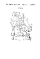
- FIG. 1 is a right side view showing one embodiment of the present invention
- FIG. 2 is a block diagram showing the protection circuit
- FIG. 3 is a view showing in detail the circuit of the present invention.
- FIG. 1 shows the right side of the inventive drilling machine with a built-in control circuit forming part of the present invention, which includes a frame 1, electromagnetic base 2 attached to the lower portion of the frame 1, and an electric drill 3 mounted on the front portion of the frame 1.
- the electric drill 3 is mounted to be vertically movable by manipulation of a manual handle 4, and an annular cutter 5 is attached to the arbor of the drill 3.
- FIG. 2 is a block diagram showing a protection circuit.
- the control circuit for the electric drill 3 includes sensor means for detecting a load impressed on the electric drill 3 as a function of a voltage change and an ON-OFF circuit.
- FIG. 3 is a view showing in detail one embodiment of the circuit according to the present invention.
- An a.c. power source portion includes a starting switch 6 which combines a control switch for the electromagnetic base 2 with a control switch for the electric drill 3.
- a starting and stopping circuit for the electric drill 3 is arranged as follows.
- the starting and stopping circuit for the electric drill 3 includes a full-wave rectification 7 for the full-wave rectification of an a.c. voltage from the power source.
- a smoothing circuit is provided which is connected to the output side of the rectifier 7 and consists of a capacitor 8, resistors 9 and 10 and a capacitor 11, and a first d.c. relay 12 connected to the output side of the smoothing circuit. Upon actuation of the relay 12, an a.c. circuit is closed at the contact of the relay 12 so that the motor 3' for the electric drill 3 is driven.
- An alarm circuit for notifying the operator of an increase in the load applied on the electric drill 3 includes an alarm means having a first a.c. relay R 1 driven through a contact 12' of the first d.c. relay 12 when the contact 12' is closed, and an emergency alarm lamp LP connected in series with a B-type contact 13 of the a.c. relay R 1 and sensor means including a resistor 15 connected in series with the motor 3' for driving the electric drill 3, a transformer 16 and a full-wave rectifier 17.
- the sensor means detects the terminal voltage of the resistor 15, which is divided by resistors 18, 19 and 20, and applied across a capacitor 21 on a second d.c. relay 23 via a first diode 22.
- the first diode 22 When the terminal voltage of the resistor 15 reaches a voltage corresponding to the first reference level that coincides with the lower load predetermined with respect to the electric drill 3, the first diode 22 is put in the ON state, so that the second d.c. relay 23 is driven with its contact 23' being closed, while the second a.c. relay R 2 is driven. The power circuit of the emergency alarm lamp LP is then closed by the A type contact 24 of the relay R 2 to send out a visual warning to the operator.
- the full-wave rectifier 17 is provided on its output side with voltage-dividing resistors 25, 26 and 27, a capacitor 28 and a second diode 29.
- the gate of a silicon-controlled element 31 is provided at one terminal of a capacitor 30 coupled to the output of a group of such control elements, and the cathode of the silicon-controlled element 31 is coupled to the other terminal of the capacitor 30, while the anode thereof is coupled to the junction of the resistors 9 and 10 of the said smoothing circuit.
- a change-over switch 32 is adapted to determine a reference load level which varies depending upon the diameter of the annular cutter used with the drilling machine.
- the reference load level can be varied by fine adjustment of the variable resistors 19 and 19', as many as 10 or more types of annular cutters having varying diameters can be used with the drilling machine according to the present invention.
- change-over switch 32 may be a two-way switch designed to be used for the detection of the cutting resistance of the annular cutter 5, that exceeds the second reference level.
- the emergency alarm lamp LP may be substituted with a suitable aural alarm device such as a buzzer.
- a limit switch 34 is coupled in parallel to the silicon-controlled element 31.
- the limit switch 34 is fixed in place within the frame 1, facing to a slide plate 35 which is supported on the front of the frame 1 in a vertically slidable manner.
- a board 36 is operatively associated with the limit switch 34 and fixed by means of a butterfly nut 37 to the inside of the slide plate 35 in a vertically adjustable manner. The board 36 is held at a given position depending upon the thickness of the workpiece. When the annular cutter 5 passes through the workpiece, the board 36 is operatively associated with the limit switch 34 to short-circuit the circuit for the silicon-controlled element 31.
- a handle 38 for a power switch 6, and a switch 40 for converting from automatic operation to manual operation are provided.
- the a.c. voltage of the a.c. power source is impressed on the full-wave rectifier 7, and the thus full-wave rectified d.c. voltage is impressed on the coil of the first d.c. relay 12 via the smoothing circuit comprising the capacitor 8, the resistor 9 coupled in series to the resistor 10 and the capacitor 11, so that the relay 12 is acutated with its contact 12' being closed, i.e., in the ON state.
- the a.c. voltage is also impressed on the driving motor 3' so as to cause rotation of the drill 3 and, at the same time, impressed on the first a.c. relay R 1 so that its contact 13 is in the OFF state.
- the electric drill 3 In drilling, the electric drill 3 is allowed to descend gradually by clockwise turning of the manual handle 4. If a load applied on the electric drill is below the predetermined reference level, drilling then proceeds with no difficulty. For instance, when the cutting edge of the annular cutter 5 is clogged with shavings, or as drilling proceeds further, a load on the annular cutter 5 is so large that it exceeds the reference level.
- the present invention is designed to detect such a large load to control the operation.
- the manual feed handle 4 is turned counterclockwise to ascend the electric drill 3, thereby taking the load off. If the annular cutter 5 is then found to be clogged with shavings, the drill 3 is shut off by manipulation of the switch 6 for removal of shavings. The load on the electric drill 3 is reduced by a series of operations as mentioned above. Thus, when the voltage on the constant-voltage diode 23 drops below the zener voltage in restarting, the voltage on the relay 23 is reduced to zero with its contact 23' returning to the original state, and the contact 24 of the relay R 2 again opening the power circuit of the emergency alarm lamp LP. The manual feed handle 4 is then turned clockwise to move the electric drill 3 toward the workpiece for drilling with the annular cutter 5.
- the feed of the electric drill 3 is shut off without identification of clogging of the drilling cutter 5 with shavings, no reduction in the load on the drill 3 takes place.
- the signal current boosted at 16 and full-wave rectified at 17 flows through the resistor 25 and the variable resistor 26, and the signal voltage larger than the voltage drawn out of the variable resistor 19 is proportionally distributed and charged in the capacitor 28.
- the anode of the silicon-controlled element 31 is connected between the resistors 9 and 10 forming the smoothing circuit for the full-wave rectifier 17, while the cathode thereof is connected to one side of the capacitor 30.
- the input side of the first d.c. relay 12 is short-circuited with its contact 12' being opened, so that the power circuit is opened to shut the driving motor 3' off.
- the electric drill 3 is ascended by counterclockwise turning of the handle 4, and the power circuit for the electric drill 3 is turned off by manipulation of the starting switch 6 to put the silicon-controlled element 31 in a nonconduction state, followed by removal of shavings. This causes the electric drill 3 to return to the state-before-operation or the initial operation state for removal of the load. Thereafter, drilling is effected under a torque lower than the reference level. Drilling is stopped when the end of the annular cutter 5 protrudes from the underside of the workpiece. To this end, the contact of the limit switch 34 is closed by the board 36 operatively associated with the slide plate 35 which has descended with the electric drill 3.
- the circuit for the silicon-controlled element 31 is short-circuited so that a potential difference across the first d.c. relay 23 is removed.
- the relay contact 12' is then in the OFF state, and the drill-driving motor 3' is automatically shut off in the same manner as in the case that the load on the electric drill 3 exceeds the predetermined value. In this way drilling is finished.
- the electric drill 3 is ascended by counterclockwise turning of the manual handle 4 until the annular cutter disengages from the workpiece. Subsequently, all the contacts of the switch 6 are opened by manipulation of the handle 38, and the electromagnetic base 2 attached to the lower portion of the frame 1 is demagnetized.
- the drilling machine according to the present invention is carried to any desired place at discretion.
- the present invention provides a drilling machine including an electric drill 3 adapted to be fixed at a desired angle with respect to a workpiece and a manual feed handle 4 adapted to move said electric drill toward and away from said workpiece, wherein the control circuit for said electric drill comprises sensor x means for detecting a load applied on said electric drill, alarm means for sending out a signal when a load signal exceeding a first reference level is detected, and switch means 12 for breaking the power circuit for said electric drill when a load signal exceeding a second reference level is detected.
- the alarm means 33 notifies the operator of overloading when such overloading is applied on the electric drill 3 during use. Furthermore, the drilling machine is automatically shut off under such overloading, thus preventing breakage of a cutter or twist drill and burning-out of a drill-driving motor.
- the drilling machine according to the present invention also protects many types of annular cutters or twist drills having different diameters against breakage and burning-out, since the detection of signal voltage can be effected by the variable resistors 19 (19'), 26 (26') and change-over switches 32 (32) in a nonstepwise manner.
Abstract
Description
Claims (5)
Applications Claiming Priority (2)
| Application Number | Priority Date | Filing Date | Title |
|---|---|---|---|
| JP57056305A JPS58177210A (en) | 1982-04-05 | 1982-04-05 | Drill |
| JP57-56305 | 1982-04-05 |
Publications (1)
| Publication Number | Publication Date |
|---|---|
| US4559577A true US4559577A (en) | 1985-12-17 |
Family
ID=13023419
Family Applications (1)
| Application Number | Title | Priority Date | Filing Date |
|---|---|---|---|
| US06/482,247 Expired - Lifetime US4559577A (en) | 1982-04-05 | 1983-04-05 | Drilling machine |
Country Status (3)
| Country | Link |
|---|---|
| US (1) | US4559577A (en) |
| JP (1) | JPS58177210A (en) |
| KR (1) | KR890000121B1 (en) |
Cited By (36)
| Publication number | Priority date | Publication date | Assignee | Title |
|---|---|---|---|---|
| US4656407A (en) * | 1985-06-14 | 1987-04-07 | A.R.A. Manufacturing Company Of Delware, Inc. | Electric motor servo control system and method |
| US4745557A (en) * | 1986-02-13 | 1988-05-17 | Ltv Aerospace & Defense Company | Machine tool control system |
| US4780654A (en) * | 1986-02-21 | 1988-10-25 | Nitto Kohki Co., Ltd. | Control apparatus for drilling machine |
| US4818227A (en) * | 1988-01-21 | 1989-04-04 | Denar Corporation | Sound producing indicators used in combination with pneumatically operated machines |
| US4831364A (en) * | 1986-03-14 | 1989-05-16 | Hitachi Koki Company, Limited | Drilling machine |
| US5007776A (en) * | 1989-06-23 | 1991-04-16 | Nitto Kohki Co., Ltd | Controller for boring apparatus |
| US5087157A (en) * | 1990-01-26 | 1992-02-11 | Nitto Kohki Co., Ltd. | Electromagnetic base drill with intermittent feed |
| US5108204A (en) * | 1989-03-31 | 1992-04-28 | Oki Electric Industry Co., Ltd. | Protective circuit for a printer driver |
| US5307049A (en) * | 1991-04-30 | 1994-04-26 | Oki Electric Industry Co., Ltd. | Alarm control method |
| US5349337A (en) * | 1992-12-15 | 1994-09-20 | Eoa Systems, Inc. | Apparatus and method for controlling peck drilling |
| US6024521A (en) * | 1997-10-23 | 2000-02-15 | Csi Technology, Inc | Electrode dresser monitoring system and method |
| US6092355A (en) * | 1994-07-22 | 2000-07-25 | Mtd Products Inc. | Control system |
| US20050025586A1 (en) * | 2003-08-01 | 2005-02-03 | Toshio Mikiya | Electric drill apparatus |
| US20050178181A1 (en) * | 2004-02-17 | 2005-08-18 | Green Jason E. | Methods and apparatus for controlling flare in roll-forming processes |
| US20060013663A1 (en) * | 2004-07-02 | 2006-01-19 | Juergen Wiehler | Drilling machine |
| US20060233621A1 (en) * | 2005-04-19 | 2006-10-19 | Schell Craig A | Electronic clutch for tool chuck with power take off and dead spindle features |
| CN100411784C (en) * | 2003-08-01 | 2008-08-20 | 日东工器株式会社 | Electric drilling device |
| US20090028653A1 (en) * | 2007-07-27 | 2009-01-29 | Wilbert Edward D | Ac/dc magnetic drill press |
| US20090065225A1 (en) * | 2007-09-07 | 2009-03-12 | Black & Decker Inc. | Switchable anti-lock control |
| US20100028093A1 (en) * | 2007-02-05 | 2010-02-04 | Kenji Otsuka | Drilling apparatus |
| US7717192B2 (en) | 2007-11-21 | 2010-05-18 | Black & Decker Inc. | Multi-mode drill with mode collar |
| US7717191B2 (en) | 2007-11-21 | 2010-05-18 | Black & Decker Inc. | Multi-mode hammer drill with shift lock |
| US20100139350A1 (en) * | 2004-02-17 | 2010-06-10 | Smith Gregory S | Methods and apparatus for controlling flare in roll-forming processes |
| US7735575B2 (en) | 2007-11-21 | 2010-06-15 | Black & Decker Inc. | Hammer drill with hard hammer support structure |
| US7762349B2 (en) | 2007-11-21 | 2010-07-27 | Black & Decker Inc. | Multi-speed drill and transmission with low gear only clutch |
| US7770660B2 (en) | 2007-11-21 | 2010-08-10 | Black & Decker Inc. | Mid-handle drill construction and assembly process |
| US7798245B2 (en) | 2007-11-21 | 2010-09-21 | Black & Decker Inc. | Multi-mode drill with an electronic switching arrangement |
| US7854274B2 (en) | 2007-11-21 | 2010-12-21 | Black & Decker Inc. | Multi-mode drill and transmission sub-assembly including a gear case cover supporting biasing |
| US20110014001A1 (en) * | 2008-03-04 | 2011-01-20 | Makino Milling Machine Co., Ltd. | Machining Method and Machine Tool |
| US20140003876A1 (en) * | 2012-06-28 | 2014-01-02 | Robert Bosch Gmbh | Handheld drill/driver device |
| US20140314506A1 (en) * | 2013-04-19 | 2014-10-23 | Milwaukee Electric Tool Corporation | Accessible temporary magnet control for magnetic drill press |
| US9561568B2 (en) | 2014-04-25 | 2017-02-07 | Black & Decker Inc. | Magnetic drill press with alternate power source |
| US20170057038A1 (en) * | 2015-09-01 | 2017-03-02 | Jpw Industries Inc. | Power tool with digital variable reluctance motor control |
| US10583539B2 (en) | 2012-04-25 | 2020-03-10 | Milwaukee Electric Tool Corporation | Magnetic drill press |
| US11745242B2 (en) | 2018-09-21 | 2023-09-05 | The Bradbury Co., Inc. | Machines to roll-form variable component geometries |
| US11919060B2 (en) | 2021-08-16 | 2024-03-05 | The Bradbury Co., Inc. | Methods and apparatus to control roll-forming processes |
Citations (8)
| Publication number | Priority date | Publication date | Assignee | Title |
|---|---|---|---|---|
| US3248629A (en) * | 1960-03-14 | 1966-04-26 | Dyna Systems Inc | Motor control system and torque indicating means |
| US3259023A (en) * | 1965-01-08 | 1966-07-05 | Applied Machine Res Inc | Metal working machine and machining process |
| US3516327A (en) * | 1968-09-24 | 1970-06-23 | Microwave Dev Lab Inc | Automatic feed and depth controller |
| US3545310A (en) * | 1968-06-14 | 1970-12-08 | Babcock & Wilcox Co | Adaptive machine tool control system |
| US3809985A (en) * | 1973-04-06 | 1974-05-07 | Pro Lect Inc | Solid state a/c motor protector system |
| US3845373A (en) * | 1972-05-22 | 1974-10-29 | K Totsu | Motor-driven screw driver with automatic stopping means |
| GB1520171A (en) * | 1976-02-24 | 1978-08-02 | Stewart & Sons Hacklemakers | Apparatus for detecting faults in drilling machines |
| US4240072A (en) * | 1979-03-19 | 1980-12-16 | Research Products Corporation | Load indicator for an air cleaner |
-
1982
- 1982-04-05 JP JP57056305A patent/JPS58177210A/en active Granted
-
1983
- 1983-03-31 KR KR1019830001315A patent/KR890000121B1/en not_active IP Right Cessation
- 1983-04-05 US US06/482,247 patent/US4559577A/en not_active Expired - Lifetime
Patent Citations (8)
| Publication number | Priority date | Publication date | Assignee | Title |
|---|---|---|---|---|
| US3248629A (en) * | 1960-03-14 | 1966-04-26 | Dyna Systems Inc | Motor control system and torque indicating means |
| US3259023A (en) * | 1965-01-08 | 1966-07-05 | Applied Machine Res Inc | Metal working machine and machining process |
| US3545310A (en) * | 1968-06-14 | 1970-12-08 | Babcock & Wilcox Co | Adaptive machine tool control system |
| US3516327A (en) * | 1968-09-24 | 1970-06-23 | Microwave Dev Lab Inc | Automatic feed and depth controller |
| US3845373A (en) * | 1972-05-22 | 1974-10-29 | K Totsu | Motor-driven screw driver with automatic stopping means |
| US3809985A (en) * | 1973-04-06 | 1974-05-07 | Pro Lect Inc | Solid state a/c motor protector system |
| GB1520171A (en) * | 1976-02-24 | 1978-08-02 | Stewart & Sons Hacklemakers | Apparatus for detecting faults in drilling machines |
| US4240072A (en) * | 1979-03-19 | 1980-12-16 | Research Products Corporation | Load indicator for an air cleaner |
Cited By (57)
| Publication number | Priority date | Publication date | Assignee | Title |
|---|---|---|---|---|
| US4656407A (en) * | 1985-06-14 | 1987-04-07 | A.R.A. Manufacturing Company Of Delware, Inc. | Electric motor servo control system and method |
| US4745557A (en) * | 1986-02-13 | 1988-05-17 | Ltv Aerospace & Defense Company | Machine tool control system |
| US4780654A (en) * | 1986-02-21 | 1988-10-25 | Nitto Kohki Co., Ltd. | Control apparatus for drilling machine |
| US4831364A (en) * | 1986-03-14 | 1989-05-16 | Hitachi Koki Company, Limited | Drilling machine |
| US4818227A (en) * | 1988-01-21 | 1989-04-04 | Denar Corporation | Sound producing indicators used in combination with pneumatically operated machines |
| US5108204A (en) * | 1989-03-31 | 1992-04-28 | Oki Electric Industry Co., Ltd. | Protective circuit for a printer driver |
| US5007776A (en) * | 1989-06-23 | 1991-04-16 | Nitto Kohki Co., Ltd | Controller for boring apparatus |
| US5087157A (en) * | 1990-01-26 | 1992-02-11 | Nitto Kohki Co., Ltd. | Electromagnetic base drill with intermittent feed |
| AU622064B2 (en) * | 1990-01-26 | 1992-03-26 | Nitto Kohki Co., Ltd. | Drill device having electromagnetic base to which swarf is difficult to cling |
| US5307049A (en) * | 1991-04-30 | 1994-04-26 | Oki Electric Industry Co., Ltd. | Alarm control method |
| US5349337A (en) * | 1992-12-15 | 1994-09-20 | Eoa Systems, Inc. | Apparatus and method for controlling peck drilling |
| US6092355A (en) * | 1994-07-22 | 2000-07-25 | Mtd Products Inc. | Control system |
| US6024521A (en) * | 1997-10-23 | 2000-02-15 | Csi Technology, Inc | Electrode dresser monitoring system and method |
| US7121773B2 (en) | 2003-08-01 | 2006-10-17 | Nitto Kohki Co., Ltd. | Electric drill apparatus |
| US20050025586A1 (en) * | 2003-08-01 | 2005-02-03 | Toshio Mikiya | Electric drill apparatus |
| CN100411784C (en) * | 2003-08-01 | 2008-08-20 | 日东工器株式会社 | Electric drilling device |
| US7111481B2 (en) * | 2004-02-17 | 2006-09-26 | The Bradbury Company | Methods and apparatus for controlling flare in roll-forming processes |
| US7591161B2 (en) | 2004-02-17 | 2009-09-22 | The Bradbury Company, Inc. | Methods and apparatus for controlling flare in roll-forming processes |
| US8453485B2 (en) | 2004-02-17 | 2013-06-04 | The Bradbury Company, Inc. | Methods and apparatus for controlling flare in roll-forming processes |
| US20060272376A1 (en) * | 2004-02-17 | 2006-12-07 | The Bradbury Company | Methods and apparatus for controlling flare in roll-forming processes |
| US20100139350A1 (en) * | 2004-02-17 | 2010-06-10 | Smith Gregory S | Methods and apparatus for controlling flare in roll-forming processes |
| US9370813B2 (en) | 2004-02-17 | 2016-06-21 | The Bradbury Company, Inc. | Methods and apparatus for controlling flare in roll-forming processes |
| US20050178181A1 (en) * | 2004-02-17 | 2005-08-18 | Green Jason E. | Methods and apparatus for controlling flare in roll-forming processes |
| AU2005200334B2 (en) * | 2004-02-17 | 2010-08-19 | The Bradbury Company, Inc. | Methods and apparatus for controlling flare in roll-forming processes |
| US7520702B2 (en) * | 2004-07-02 | 2009-04-21 | C. & E. Fein Gmbh | Drilling machine |
| US20060013663A1 (en) * | 2004-07-02 | 2006-01-19 | Juergen Wiehler | Drilling machine |
| US7677844B2 (en) * | 2005-04-19 | 2010-03-16 | Black & Decker Inc. | Electronic clutch for tool chuck with power take off and dead spindle features |
| US20060233621A1 (en) * | 2005-04-19 | 2006-10-19 | Schell Craig A | Electronic clutch for tool chuck with power take off and dead spindle features |
| US20100028093A1 (en) * | 2007-02-05 | 2010-02-04 | Kenji Otsuka | Drilling apparatus |
| US20090028653A1 (en) * | 2007-07-27 | 2009-01-29 | Wilbert Edward D | Ac/dc magnetic drill press |
| US8376667B2 (en) | 2007-07-27 | 2013-02-19 | Milwaukee Electric Tool Corporation | AC/DC magnetic drill press |
| US20090065225A1 (en) * | 2007-09-07 | 2009-03-12 | Black & Decker Inc. | Switchable anti-lock control |
| US7717192B2 (en) | 2007-11-21 | 2010-05-18 | Black & Decker Inc. | Multi-mode drill with mode collar |
| US7770660B2 (en) | 2007-11-21 | 2010-08-10 | Black & Decker Inc. | Mid-handle drill construction and assembly process |
| US7798245B2 (en) | 2007-11-21 | 2010-09-21 | Black & Decker Inc. | Multi-mode drill with an electronic switching arrangement |
| US7854274B2 (en) | 2007-11-21 | 2010-12-21 | Black & Decker Inc. | Multi-mode drill and transmission sub-assembly including a gear case cover supporting biasing |
| US7717191B2 (en) | 2007-11-21 | 2010-05-18 | Black & Decker Inc. | Multi-mode hammer drill with shift lock |
| US7987920B2 (en) | 2007-11-21 | 2011-08-02 | Black & Decker Inc. | Multi-mode drill with mode collar |
| US8109343B2 (en) | 2007-11-21 | 2012-02-07 | Black & Decker Inc. | Multi-mode drill with mode collar |
| US8292001B2 (en) | 2007-11-21 | 2012-10-23 | Black & Decker Inc. | Multi-mode drill with an electronic switching arrangement |
| US7762349B2 (en) | 2007-11-21 | 2010-07-27 | Black & Decker Inc. | Multi-speed drill and transmission with low gear only clutch |
| US7735575B2 (en) | 2007-11-21 | 2010-06-15 | Black & Decker Inc. | Hammer drill with hard hammer support structure |
| US20110014001A1 (en) * | 2008-03-04 | 2011-01-20 | Makino Milling Machine Co., Ltd. | Machining Method and Machine Tool |
| US8668412B2 (en) * | 2008-03-04 | 2014-03-11 | Makino Milling Machine Co., Ltd. | Machining method and machine tool |
| US10583539B2 (en) | 2012-04-25 | 2020-03-10 | Milwaukee Electric Tool Corporation | Magnetic drill press |
| CN103507021A (en) * | 2012-06-28 | 2014-01-15 | 罗伯特·博世有限公司 | Handheld drill screwing device |
| US20140003876A1 (en) * | 2012-06-28 | 2014-01-02 | Robert Bosch Gmbh | Handheld drill/driver device |
| US9366299B2 (en) * | 2012-06-28 | 2016-06-14 | Robert Bosch Gmbh | Handheld drill/driver device |
| US20140314506A1 (en) * | 2013-04-19 | 2014-10-23 | Milwaukee Electric Tool Corporation | Accessible temporary magnet control for magnetic drill press |
| US9849581B2 (en) * | 2013-04-19 | 2017-12-26 | Milwaukee Electric Tool Corporation | Accessible temporary magnet control for magnetic drill press |
| US10118265B2 (en) | 2014-04-25 | 2018-11-06 | Black & Decker, Inc. | Magnetic drill press with alternate power source |
| US10369670B2 (en) | 2014-04-25 | 2019-08-06 | Black & Decker, Inc. | Magnetic drill press with alternate power source |
| US9561568B2 (en) | 2014-04-25 | 2017-02-07 | Black & Decker Inc. | Magnetic drill press with alternate power source |
| US20170057038A1 (en) * | 2015-09-01 | 2017-03-02 | Jpw Industries Inc. | Power tool with digital variable reluctance motor control |
| US10189136B2 (en) * | 2015-09-01 | 2019-01-29 | Jpw Industries Inc. | Power tool with digital variable reluctance motor control |
| US11745242B2 (en) | 2018-09-21 | 2023-09-05 | The Bradbury Co., Inc. | Machines to roll-form variable component geometries |
| US11919060B2 (en) | 2021-08-16 | 2024-03-05 | The Bradbury Co., Inc. | Methods and apparatus to control roll-forming processes |
Also Published As
| Publication number | Publication date |
|---|---|
| JPS58177210A (en) | 1983-10-17 |
| JPS626925B2 (en) | 1987-02-14 |
| KR890000121B1 (en) | 1989-03-08 |
Similar Documents
| Publication | Publication Date | Title |
|---|---|---|
| US4559577A (en) | Drilling machine | |
| KR860000144B1 (en) | Drilling machine having an electromagnetic base | |
| EP2127790B1 (en) | Drilling apparatus | |
| EP1016481B1 (en) | Control device for boring machine | |
| US4873474A (en) | Winch with shut-off load limiter | |
| JPS57144638A (en) | Protective device for automatic tool changing device | |
| US4278371A (en) | Safety interlock for electro-magnetic drill stand | |
| KR20060032214A (en) | Electric drill apparatus | |
| CA2010132A1 (en) | Method of detecting failure to tighten screws against works and device therefor | |
| GB2051362A (en) | Monitoring tool life | |
| EP0349929B1 (en) | Switch with pre-alarm means | |
| US5251522A (en) | Protective apparatus preventing lathe tool from breaking | |
| JP4043420B2 (en) | Electric drilling device with automatic redrive function | |
| JPS63283807A (en) | Boring machine | |
| DE2919782C2 (en) | Device for monitoring the switching status of a battery-operated electromagnet, in particular a lifting magnet of a hoist | |
| JPS6246488Y2 (en) | ||
| JP2000198005A (en) | Automatic feeding control device | |
| GB2124765A (en) | Monitoring sawing operation | |
| US4866358A (en) | Motor control circuit with vibration detector | |
| JPS59124507A (en) | Drilling machine | |
| GB2600572A (en) | Portable machining tool | |
| US4365122A (en) | Machine control device | |
| JPH08223916A (en) | Power supply circuit | |
| KR100402406B1 (en) | An Axis feed Control Device With Safety Consideration | |
| JP2003025122A (en) | Control device for portable electric drill device |
Legal Events
| Date | Code | Title | Description |
|---|---|---|---|
| AS | Assignment |
Owner name: NITTO KOHKI CO., LTD.; 9-4, NAKAIKEGAMI 2-CHOME, O Free format text: ASSIGNMENT OF ASSIGNORS INTEREST.;ASSIGNORS:SHOJI, MICHIHIRO;MIKIYA, TOSHIO;REEL/FRAME:004114/0855 Effective date: 19830330 |
|
| STCF | Information on status: patent grant |
Free format text: PATENTED CASE |
|
| FEPP | Fee payment procedure |
Free format text: PAYOR NUMBER ASSIGNED (ORIGINAL EVENT CODE: ASPN); ENTITY STATUS OF PATENT OWNER: LARGE ENTITY |
|
| FPAY | Fee payment |
Year of fee payment: 4 |
|
| FEPP | Fee payment procedure |
Free format text: PAYER NUMBER DE-ASSIGNED (ORIGINAL EVENT CODE: RMPN); ENTITY STATUS OF PATENT OWNER: LARGE ENTITY Free format text: PAYOR NUMBER ASSIGNED (ORIGINAL EVENT CODE: ASPN); ENTITY STATUS OF PATENT OWNER: LARGE ENTITY |
|
| FEPP | Fee payment procedure |
Free format text: PAYER NUMBER DE-ASSIGNED (ORIGINAL EVENT CODE: RMPN); ENTITY STATUS OF PATENT OWNER: LARGE ENTITY Free format text: PAYOR NUMBER ASSIGNED (ORIGINAL EVENT CODE: ASPN); ENTITY STATUS OF PATENT OWNER: LARGE ENTITY |
|
| FPAY | Fee payment |
Year of fee payment: 8 |
|
| FEPP | Fee payment procedure |
Free format text: PAT HLDR NO LONGER CLAIMS SMALL ENT STAT AS SMALL BUSINESS (ORIGINAL EVENT CODE: LSM2); ENTITY STATUS OF PATENT OWNER: LARGE ENTITY |
|
| FPAY | Fee payment |
Year of fee payment: 12 |