US4563589A - Ultraviolet curing lamp device - Google Patents
Ultraviolet curing lamp device Download PDFInfo
- Publication number
- US4563589A US4563589A US06/569,320 US56932084A US4563589A US 4563589 A US4563589 A US 4563589A US 56932084 A US56932084 A US 56932084A US 4563589 A US4563589 A US 4563589A
- Authority
- US
- United States
- Prior art keywords
- ultraviolet light
- light source
- cold mirror
- housing
- heat absorber
- Prior art date
- Legal status (The legal status is an assumption and is not a legal conclusion. Google has not performed a legal analysis and makes no representation as to the accuracy of the status listed.)
- Expired - Fee Related
Links
Images


Classifications
-
- F—MECHANICAL ENGINEERING; LIGHTING; HEATING; WEAPONS; BLASTING
- F21—LIGHTING
- F21V—FUNCTIONAL FEATURES OR DETAILS OF LIGHTING DEVICES OR SYSTEMS THEREOF; STRUCTURAL COMBINATIONS OF LIGHTING DEVICES WITH OTHER ARTICLES, NOT OTHERWISE PROVIDED FOR
- F21V29/00—Protecting lighting devices from thermal damage; Cooling or heating arrangements specially adapted for lighting devices or systems
- F21V29/50—Cooling arrangements
- F21V29/60—Cooling arrangements characterised by the use of a forced flow of gas, e.g. air
- F21V29/67—Cooling arrangements characterised by the use of a forced flow of gas, e.g. air characterised by the arrangement of fans
- F21V29/677—Cooling arrangements characterised by the use of a forced flow of gas, e.g. air characterised by the arrangement of fans the fans being used for discharging
-
- B—PERFORMING OPERATIONS; TRANSPORTING
- B29—WORKING OF PLASTICS; WORKING OF SUBSTANCES IN A PLASTIC STATE IN GENERAL
- B29C—SHAPING OR JOINING OF PLASTICS; SHAPING OF MATERIAL IN A PLASTIC STATE, NOT OTHERWISE PROVIDED FOR; AFTER-TREATMENT OF THE SHAPED PRODUCTS, e.g. REPAIRING
- B29C35/00—Heating, cooling or curing, e.g. crosslinking or vulcanising; Apparatus therefor
- B29C35/02—Heating or curing, e.g. crosslinking or vulcanizing during moulding, e.g. in a mould
- B29C35/08—Heating or curing, e.g. crosslinking or vulcanizing during moulding, e.g. in a mould by wave energy or particle radiation
-
- B—PERFORMING OPERATIONS; TRANSPORTING
- B29—WORKING OF PLASTICS; WORKING OF SUBSTANCES IN A PLASTIC STATE IN GENERAL
- B29C—SHAPING OR JOINING OF PLASTICS; SHAPING OF MATERIAL IN A PLASTIC STATE, NOT OTHERWISE PROVIDED FOR; AFTER-TREATMENT OF THE SHAPED PRODUCTS, e.g. REPAIRING
- B29C35/00—Heating, cooling or curing, e.g. crosslinking or vulcanising; Apparatus therefor
- B29C35/16—Cooling
-
- B—PERFORMING OPERATIONS; TRANSPORTING
- B41—PRINTING; LINING MACHINES; TYPEWRITERS; STAMPS
- B41F—PRINTING MACHINES OR PRESSES
- B41F23/00—Devices for treating the surfaces of sheets, webs, or other articles in connection with printing
- B41F23/04—Devices for treating the surfaces of sheets, webs, or other articles in connection with printing by heat drying, by cooling, by applying powders
- B41F23/0403—Drying webs
- B41F23/0406—Drying webs by radiation
- B41F23/0409—Ultra-violet dryers
-
- F—MECHANICAL ENGINEERING; LIGHTING; HEATING; WEAPONS; BLASTING
- F21—LIGHTING
- F21V—FUNCTIONAL FEATURES OR DETAILS OF LIGHTING DEVICES OR SYSTEMS THEREOF; STRUCTURAL COMBINATIONS OF LIGHTING DEVICES WITH OTHER ARTICLES, NOT OTHERWISE PROVIDED FOR
- F21V29/00—Protecting lighting devices from thermal damage; Cooling or heating arrangements specially adapted for lighting devices or systems
- F21V29/50—Cooling arrangements
- F21V29/70—Cooling arrangements characterised by passive heat-dissipating elements, e.g. heat-sinks
- F21V29/83—Cooling arrangements characterised by passive heat-dissipating elements, e.g. heat-sinks the elements having apertures, ducts or channels, e.g. heat radiation holes
-
- F—MECHANICAL ENGINEERING; LIGHTING; HEATING; WEAPONS; BLASTING
- F26—DRYING
- F26B—DRYING SOLID MATERIALS OR OBJECTS BY REMOVING LIQUID THEREFROM
- F26B3/00—Drying solid materials or objects by processes involving the application of heat
- F26B3/28—Drying solid materials or objects by processes involving the application of heat by radiation, e.g. from the sun
-
- H—ELECTRICITY
- H05—ELECTRIC TECHNIQUES NOT OTHERWISE PROVIDED FOR
- H05B—ELECTRIC HEATING; ELECTRIC LIGHT SOURCES NOT OTHERWISE PROVIDED FOR; CIRCUIT ARRANGEMENTS FOR ELECTRIC LIGHT SOURCES, IN GENERAL
- H05B3/00—Ohmic-resistance heating
- H05B3/0033—Heating devices using lamps
- H05B3/0038—Heating devices using lamps for industrial applications
- H05B3/0057—Heating devices using lamps for industrial applications for plastic handling and treatment
-
- H—ELECTRICITY
- H05—ELECTRIC TECHNIQUES NOT OTHERWISE PROVIDED FOR
- H05B—ELECTRIC HEATING; ELECTRIC LIGHT SOURCES NOT OTHERWISE PROVIDED FOR; CIRCUIT ARRANGEMENTS FOR ELECTRIC LIGHT SOURCES, IN GENERAL
- H05B3/00—Ohmic-resistance heating
- H05B3/0033—Heating devices using lamps
- H05B3/0038—Heating devices using lamps for industrial applications
- H05B3/0066—Heating devices using lamps for industrial applications for photocopying
-
- B—PERFORMING OPERATIONS; TRANSPORTING
- B29—WORKING OF PLASTICS; WORKING OF SUBSTANCES IN A PLASTIC STATE IN GENERAL
- B29C—SHAPING OR JOINING OF PLASTICS; SHAPING OF MATERIAL IN A PLASTIC STATE, NOT OTHERWISE PROVIDED FOR; AFTER-TREATMENT OF THE SHAPED PRODUCTS, e.g. REPAIRING
- B29C35/00—Heating, cooling or curing, e.g. crosslinking or vulcanising; Apparatus therefor
- B29C35/02—Heating or curing, e.g. crosslinking or vulcanizing during moulding, e.g. in a mould
- B29C35/08—Heating or curing, e.g. crosslinking or vulcanizing during moulding, e.g. in a mould by wave energy or particle radiation
- B29C35/0805—Heating or curing, e.g. crosslinking or vulcanizing during moulding, e.g. in a mould by wave energy or particle radiation using electromagnetic radiation
- B29C2035/0827—Heating or curing, e.g. crosslinking or vulcanizing during moulding, e.g. in a mould by wave energy or particle radiation using electromagnetic radiation using UV radiation
Definitions
- the present invention relates to an "ultraviolet curing lamp device" for the curing of organic compound products and especially photopolymerizable materials. It is particularly directed to such a device which may be operated at temperatures lower than the conventional air cooled devices and, is capable of curing a broader spectrum of products, some of which could not maintain their integrity at higher curing temperatures. Further, it is directed to a device which is air cooled rather than water cooled.
- U.S. Pat. No. 4.309,616 is directed to an apparatus for producing ultraviolet radiation for treatment of humans but operates in the radiation range of 315 nm to 400 nm.
- the patent describes heat absorbing and intercepting means including an auxiliary reflector in front of a radiation source as well as an air cooling means located behind an ultraviolet light source reflector. While this patent is directed to ultraviolet light radiation, it does not have the requisite output for curing photopolymerizable materials and is directed to tanning humans. Thus, the patent fails to teach any of the physical improvements embodied in the present device of the invention.
- U.S. Pat. No. 4,298,806 describes an apparatus for ultraviolet curing and includes air cooling means as well as an ellipsoidal reflector.
- this patent utilizes a long, curved optical wave guide and a thin film filter of titanium dioxide.
- the wave guide is designed to be bent at an angle such that cool ultraviolet light, i.e., radiation, is emitted.
- the present invention eliminates the need for a wave guide and enables much higher powered outputs to be utilized at substantially lowered temperatures.
- U.S. Pat. No. 4,274,028 is directed to an apparatus for generating ultraviolet light of high intensity without heat production but requires a complex anode/cathode arrangement as well as vacuum-producing equipment.
- This patent teaches a device which is very different from that of the present invention. Due to the four different air currents utilized in the device of the present invention, this type of prior art evacuation as well as other prior art techniques such as water cooling, is eliminated.
- U.S. Pat. No. 4,101,424 is directed to an ultraviolet lamp device employing a water jacket and heat exchanger to effect cooling. Again, unlike the present invention, this prior art requires water circulation. It should be noted that the present invention does not include a water circulation system, and, to make a comparison, in general, water circulation systems require plumbing, more expensive hardware, pumping, filtering, de-ionizing, and may create the potential for hazard due to the combination of high voltage or current being utilized in the same device through which water passes. As mentioned, all of these problems are eliminated by the present invention device.
- U.S. Pat. No. 4,055,769 teaches a method and apparatus for curing a coating on a substrate wherein an ultraviolet light source is used in conjunction with a reflector which includes two opposite quarter circular concave sections and two partial parabolic sections.
- a reflector which includes two opposite quarter circular concave sections and two partial parabolic sections.
- hot mirrors such as aluminum which is vaporized with quartz, are used and the very low temperatures at high outputs which are achieved with the present invention cannot be obtained with this prior art device.
- the invention described in this patent is directed to a very narrow band of ultraviolet light and could not successfully be employed with broad band curing such as is used in the present invention.
- U.S. Pat. No. 4,048,490 describes an apparatus for delivering a relatively cold ultraviolet light to a substrate for ultraviolet curing. While this patent teaches the use of dichroic reflective surfaces, it should be noted that these surfaces are flat and do not have focal points and, more importantly, are described in conjunction with a system which requires water cooling to lower the temperature of operation. As mentioned above, the use of water cooling systems creates many undesirable features which the present invention eliminates.
- the present invention is directed to an ultraviolet device used for curing photopolymerizable materials. Its features include a cold mirror of the converging type having at least one focal point and located behind an ultraviolet light source, a heat absorber behind the cold mirror, a back deflector behind the heat absorber, and a blocker tube and an ultraviolet light permeable window located in front of the ultraviolet light source. These features are arranged so as to provide four different channels for cooling, thereby enabling the device to be operated at very low temperatures without the need for evacuation and without the need for water cooling.
- a longitudinal current air channel is located inside of the blocker tube and a second longitudinal channel permits cooling air to pass over the outside of the blocker tube, over the window, with some air movement over the ultraviolet light source and the front of the cold mirror.
- a first cross current of cooling air passes at a right angle to the longitudinal dimension of the ultraviolet light source between the cold mirror and the heat absorber and a second cross current passes between the heat absorber and the back deflector. Adequate air movement is provided so as to enable the device to be operated at greatly reduced temperatures, as measured at the focal point(s) of the cold mirror.
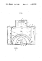
- FIG. 1 is a cut sectional side view of one embodiment of the device of the present invention which shows two cross current air channels;
- FIG. 2 is a cut sectional front view of one embodiment of a device of the present invention which shows two longitudinally current air channels;
- FIG. 3 illustrates schematically the possible ultraviolet light paths in a present invention device from the light source to the product to be cured
- FIG. 4 illustrates the air flow paths for both the longitudinal currents and the cross currents in a device of the present invention.
- present invention device 1 contains within it an ultraviolet light source 3 which is a longitudinal, cylindrical bulb with its longitudinal dimension shown in FIG. 2.
- Cold mirror 5 is a converging mirror (e.g. parabolic or elliptical), shown here as two parabolic half sections each having one focal point onto which light converges.
- Cold mirror 5 is made of quartz and includes a multilayer dichroic filter to selectively reflect a broad band of ultraviolet light.
- Cold mirror 5 is located within device 1 in a longitudinally parallel relationship to ultraviolet light source 3 so as to selectively reflect ultraviolet light out of device 1 and through ultraviolet light permeable window 43, in this case, a quartz plate window.
- Heat absorber 7 is shown within the device 1 and behind cold mirror 5 so as to place cold mirror 5 between it and ultraviolet light source 3. This creates an air space between the back of cold mirror 5 and the front of heat absorber 7. As shown, heat absorber 7 has an arcuated configuration running longitudinally parallel to ultraviolet light source 3. Heat absorber cross current outlet 9 and heat absorber cross current inlets 11 allow cross current air to flow over the back of cold mirror 5 and the front of heat absorber 7.
- Back deflector 13 is also located within device 1 and is specifically located behind heat absorber 7 so as to place heat absorber 7 between cold mirror 5 and back deflector 13 and so as to create a space between heat absorber 7 and back deflector 13.
- Back deflector 13 has an arcuated configuration running longitudinally parallel to ultraviolet light source 3.
- Back deflector cross current inlets 17 and outlet 15 enable cross current air to pass over the back of heat absorber 7 and the front of back deflector 13.
- Blocker tube 19 is located within device 1 between ultraviolet light source 3 and window 43.
- Blocker tube 19 is hollow and thus contains a longitudinal air current channel 21.
- Blocker tube 19 reflects ultraviolet, visible and infrared light which would otherwise pass straight through window 43 from ultraviolet light source 3 and thereby reduces non-ultraviolet light and heat from passing directly through quartz plate window 43.
- Device 1 includes housing base 23 and housing cover 25. Also, a deflector chamber wall 61 (shown in FIG. 1) and support wall 63 (shown in FIG. 2) are contained within housing base 23 and housing cover 25.
- FIG. 2 shows ultraviolet light source 3 connected to socket 65 and support 67, which support is attached to housing cover 25.
- a first longitudinal current air channel 21 within blocker tube 19 permits cooling air to flow through it during operation of ultraviolet light source 3.
- a second longitudinal air channel 39 is connected within device 1 so as to permit cooling air to flow longitudinally over the outside of blocker tube 19, and over quartz plate window 43, with some air movement over ultraviolet light source 3 and the front surface of cold mirror 5.
- inlet 29 provides air for channel 21 and channel 39 via conduit 33.
- air enters at inlet 29, passes down conduit 33 and forms two longitudinal currents of air, one through channel 21 and one through channel 39.
- These two longitudinal currents converge again within outlet conduit 35 and then exit housing cover 35 via outlet 31.
- the longitudinal currents air enters housing duct 45 enclosed by frame 47 and exits duct 45 via outlet 49 into exhaust chimney 51.
- the longitudinal currents may be regulated by optional outlet regulator valve 69 which contols outlet regulator plate 71 to constrict passage through duct 45, as desired.
- a first cross current air channel is, as mentioned, created between cold mirror 5 and heat absorber 7 and a second cross current air channel is created between heat absorber 7 and a back deflector 13.
- Air enters housing cover 25 via cross current inlets 27.
- the air passes over baffles 37 and enters the first cross current air channel via inlets 11, that air passes at a right angle to the longitudinal dimension of ultraviolet light source 3 between cold mirror reflector 5 and heat absorber 7, and exits via outlet 9.
- a portion of the air entering inlets 27 enters the second cross current air channel via inlets 17, passes at a right angle to the longitudinal dimension of ultraviolet light source 3 between heat absorber 7 and back deflector 13, and exits via outlet I5.
- Blocker tube support plate 41 (actually the lower section of support wall 63) is shown with spacing at its base (FIG. 1) as well as spacing around ultraviolet light source 3 (FIG. 2). This enables the above-mentioned second longitudinal current air channel to simultaneously pass longitudinally about blocker tube 19, and over quartz plate window 43 as discussed above.
- support plate 41 could be employed provided that adequate flow of the second longitudinal current could be achieved.
- FIGS. 1 and 2 illustrate air movement means in exhaust chimney 51 which is capable of moving both of the longitudinal currents and both of the cross currents at a cooling rate so as to enable the operation of said ultraviolet light source at greatly reduced temperatures as measured at the cold mirror focal point.
- operation was possible at temperatures no greater than 320° F. when measured adjacent to the outside of quartz plate window 43 (the focal point, in this embodiment).
- chimney inlet 53 FIG. 2 allows exhaust from the cross currents to enter chimney 51 and outlet 49 allows exhaust from the longitudinal currents to enter chimney 51. All of the air currents are exhausted with exhaust fan 57 and exhaust fan shaft 59 which is connected to a power source (not shown) so as to adequately move these air currents through chimney outlet 55 to the at- mosphere.
- Ultraviolet light curable organic compound product shown symbolically as arrow 81 in FIG. 1 moves at a right angle to the longitudinal dimension of ultraviolet light below quartz plate window 43 to effect the desired curing.
- FIG. 3 illustrates the possible paths for ultraviolet light source 3 in the device shown in FIGS. 1 and 2.
- the ultraviolet light may go to the blocker tube, to the cold mirror and through the window directly (albeit, at an angle).
- Ultraviolet light may deflect off the blocker tube to the cold mirror and vice versa, and then through the window.
- Ultraviolet light traveling through any of these paths may ultimately impinge upon the product which is to be cured to effect the desired curing results.
- FIG. 4 merely illustrates schematically the cooling air paths utilized in a device of the present invention.
Abstract
The present invention device is used for curing photopolymerizable products and includes a converging type cold mirror, an ultraviolet light source, a heat absorber behind the cold mirror, a back deflector behind the heat absorber, and a blocker tube and an ultraviolet light permeable window located in front of the ultraviolet light source. The various elements are arranged so as to provide four different air channels (two longitudinal currents and two cross currents) for cooling, enabling the device to be operated at greatly reduced temperatures as compared to prior art air cooled devices.
Description
1. Field of the Invention
The present invention relates to an "ultraviolet curing lamp device" for the curing of organic compound products and especially photopolymerizable materials. It is particularly directed to such a device which may be operated at temperatures lower than the conventional air cooled devices and, is capable of curing a broader spectrum of products, some of which could not maintain their integrity at higher curing temperatures. Further, it is directed to a device which is air cooled rather than water cooled.
2. Prior Art Statement
The use of ultraviolet lamps for curing various organic compound materials is well known. Thus, photopolymerizable inks and plastics are cured upon exposure to ultraviolet radiation.
U.S. Pat. No. 4.309,616 is directed to an apparatus for producing ultraviolet radiation for treatment of humans but operates in the radiation range of 315 nm to 400 nm. The patent describes heat absorbing and intercepting means including an auxiliary reflector in front of a radiation source as well as an air cooling means located behind an ultraviolet light source reflector. While this patent is directed to ultraviolet light radiation, it does not have the requisite output for curing photopolymerizable materials and is directed to tanning humans. Thus, the patent fails to teach any of the physical improvements embodied in the present device of the invention.
U.S. Pat. No. 4,298,806 describes an apparatus for ultraviolet curing and includes air cooling means as well as an ellipsoidal reflector. However, this patent utilizes a long, curved optical wave guide and a thin film filter of titanium dioxide. The wave guide is designed to be bent at an angle such that cool ultraviolet light, i.e., radiation, is emitted. The present invention eliminates the need for a wave guide and enables much higher powered outputs to be utilized at substantially lowered temperatures.
U.S. Pat. No. 4,274,028 is directed to an apparatus for generating ultraviolet light of high intensity without heat production but requires a complex anode/cathode arrangement as well as vacuum-producing equipment. This patent teaches a device which is very different from that of the present invention. Due to the four different air currents utilized in the device of the present invention, this type of prior art evacuation as well as other prior art techniques such as water cooling, is eliminated.
U.S. Pat. No. 4,101,424 is directed to an ultraviolet lamp device employing a water jacket and heat exchanger to effect cooling. Again, unlike the present invention, this prior art requires water circulation. It should be noted that the present invention does not include a water circulation system, and, to make a comparison, in general, water circulation systems require plumbing, more expensive hardware, pumping, filtering, de-ionizing, and may create the potential for hazard due to the combination of high voltage or current being utilized in the same device through which water passes. As mentioned, all of these problems are eliminated by the present invention device.
U.S. Pat. No. 4,055,769 teaches a method and apparatus for curing a coating on a substrate wherein an ultraviolet light source is used in conjunction with a reflector which includes two opposite quarter circular concave sections and two partial parabolic sections. In this patent, hot mirrors such as aluminum which is vaporized with quartz, are used and the very low temperatures at high outputs which are achieved with the present invention cannot be obtained with this prior art device. In fact, the invention described in this patent is directed to a very narrow band of ultraviolet light and could not successfully be employed with broad band curing such as is used in the present invention.
U.S. Pat. No. 4,048,490 describes an apparatus for delivering a relatively cold ultraviolet light to a substrate for ultraviolet curing. While this patent teaches the use of dichroic reflective surfaces, it should be noted that these surfaces are flat and do not have focal points and, more importantly, are described in conjunction with a system which requires water cooling to lower the temperature of operation. As mentioned above, the use of water cooling systems creates many undesirable features which the present invention eliminates.
The present invention is directed to an ultraviolet device used for curing photopolymerizable materials. Its features include a cold mirror of the converging type having at least one focal point and located behind an ultraviolet light source, a heat absorber behind the cold mirror, a back deflector behind the heat absorber, and a blocker tube and an ultraviolet light permeable window located in front of the ultraviolet light source. These features are arranged so as to provide four different channels for cooling, thereby enabling the device to be operated at very low temperatures without the need for evacuation and without the need for water cooling. Specifically, a longitudinal current air channel is located inside of the blocker tube and a second longitudinal channel permits cooling air to pass over the outside of the blocker tube, over the window, with some air movement over the ultraviolet light source and the front of the cold mirror. Additionally, a first cross current of cooling air passes at a right angle to the longitudinal dimension of the ultraviolet light source between the cold mirror and the heat absorber and a second cross current passes between the heat absorber and the back deflector. Adequate air movement is provided so as to enable the device to be operated at greatly reduced temperatures, as measured at the focal point(s) of the cold mirror.
Various other objects, features and attendant advantages of the present invention will be more fully appreciated as the same becomes better understood from the following detailed description in connection with the accompanying drawings, in which like reference characters designate like or corresponding parts through the several views and wherein:
FIG. 1 is a cut sectional side view of one embodiment of the device of the present invention which shows two cross current air channels;
FIG. 2 is a cut sectional front view of one embodiment of a device of the present invention which shows two longitudinally current air channels;
FIG. 3 illustrates schematically the possible ultraviolet light paths in a present invention device from the light source to the product to be cured; and,
FIG. 4 illustrates the air flow paths for both the longitudinal currents and the cross currents in a device of the present invention.
In FIGS. 1 and 2, present invention device 1 contains within it an ultraviolet light source 3 which is a longitudinal, cylindrical bulb with its longitudinal dimension shown in FIG. 2. Cold mirror 5 is a converging mirror (e.g. parabolic or elliptical), shown here as two parabolic half sections each having one focal point onto which light converges. Cold mirror 5 is made of quartz and includes a multilayer dichroic filter to selectively reflect a broad band of ultraviolet light. Cold mirror 5 is located within device 1 in a longitudinally parallel relationship to ultraviolet light source 3 so as to selectively reflect ultraviolet light out of device 1 and through ultraviolet light permeable window 43, in this case, a quartz plate window.
Heat absorber 7 is shown within the device 1 and behind cold mirror 5 so as to place cold mirror 5 between it and ultraviolet light source 3. This creates an air space between the back of cold mirror 5 and the front of heat absorber 7. As shown, heat absorber 7 has an arcuated configuration running longitudinally parallel to ultraviolet light source 3. Heat absorber cross current outlet 9 and heat absorber cross current inlets 11 allow cross current air to flow over the back of cold mirror 5 and the front of heat absorber 7.
Device 1 includes housing base 23 and housing cover 25. Also, a deflector chamber wall 61 (shown in FIG. 1) and support wall 63 (shown in FIG. 2) are contained within housing base 23 and housing cover 25.
FIG. 2 shows ultraviolet light source 3 connected to socket 65 and support 67, which support is attached to housing cover 25.
A first longitudinal current air channel 21 within blocker tube 19 permits cooling air to flow through it during operation of ultraviolet light source 3. A second longitudinal air channel 39 is connected within device 1 so as to permit cooling air to flow longitudinally over the outside of blocker tube 19, and over quartz plate window 43, with some air movement over ultraviolet light source 3 and the front surface of cold mirror 5. As illustrated in FIG. 2, inlet 29 provides air for channel 21 and channel 39 via conduit 33. Thus air enters at inlet 29, passes down conduit 33 and forms two longitudinal currents of air, one through channel 21 and one through channel 39. These two longitudinal currents converge again within outlet conduit 35 and then exit housing cover 35 via outlet 31. From outlet 31, the longitudinal currents air enters housing duct 45 enclosed by frame 47 and exits duct 45 via outlet 49 into exhaust chimney 51. As shown in FIG. 2, the longitudinal currents may be regulated by optional outlet regulator valve 69 which contols outlet regulator plate 71 to constrict passage through duct 45, as desired.
A first cross current air channel is, as mentioned, created between cold mirror 5 and heat absorber 7 and a second cross current air channel is created between heat absorber 7 and a back deflector 13. Air enters housing cover 25 via cross current inlets 27. The air passes over baffles 37 and enters the first cross current air channel via inlets 11, that air passes at a right angle to the longitudinal dimension of ultraviolet light source 3 between cold mirror reflector 5 and heat absorber 7, and exits via outlet 9. In addition, a portion of the air entering inlets 27 enters the second cross current air channel via inlets 17, passes at a right angle to the longitudinal dimension of ultraviolet light source 3 between heat absorber 7 and back deflector 13, and exits via outlet I5.
Blocker tube support plate 41 (actually the lower section of support wall 63) is shown with spacing at its base (FIG. 1) as well as spacing around ultraviolet light source 3 (FIG. 2). This enables the above-mentioned second longitudinal current air channel to simultaneously pass longitudinally about blocker tube 19, and over quartz plate window 43 as discussed above. However, it should be noted that other configurations of support plate 41 could be employed provided that adequate flow of the second longitudinal current could be achieved.
FIGS. 1 and 2 illustrate air movement means in exhaust chimney 51 which is capable of moving both of the longitudinal currents and both of the cross currents at a cooling rate so as to enable the operation of said ultraviolet light source at greatly reduced temperatures as measured at the cold mirror focal point. For example, in this embodiment, operation was possible at temperatures no greater than 320° F. when measured adjacent to the outside of quartz plate window 43 (the focal point, in this embodiment). Specifically, chimney inlet 53 (FIG. 2) allows exhaust from the cross currents to enter chimney 51 and outlet 49 allows exhaust from the longitudinal currents to enter chimney 51. All of the air currents are exhausted with exhaust fan 57 and exhaust fan shaft 59 which is connected to a power source (not shown) so as to adequately move these air currents through chimney outlet 55 to the at- mosphere.
Ultraviolet light curable organic compound product shown symbolically as arrow 81 in FIG. 1 moves at a right angle to the longitudinal dimension of ultraviolet light below quartz plate window 43 to effect the desired curing.
FIG. 3 illustrates the possible paths for ultraviolet light source 3 in the device shown in FIGS. 1 and 2. Thus, the ultraviolet light may go to the blocker tube, to the cold mirror and through the window directly (albeit, at an angle). Ultraviolet light may deflect off the blocker tube to the cold mirror and vice versa, and then through the window. Ultraviolet light traveling through any of these paths may ultimately impinge upon the product which is to be cured to effect the desired curing results.
FIG. 4 merely illustrates schematically the cooling air paths utilized in a device of the present invention.
Obviously, numerous modifications and variations of the present invention are possible in light of the above teachings. It is therefore to be understood that within the scope of the appended claims, the invention may be practiced otherwise than as specifically described herein.
Claims (5)
1. A device for curing ultraviolet light curable organic compound products which comprises:
(a) an ultraviolet light housing which includes an ultraviolet light permeable window;
(b) an ultraviolet light source of a longitudinal cylindrical nature contained within said housing;
(c) a cold mirror of the converging type having at least one focal point and being comprised of quartz with a multi-layer dichroic filter thereon to selectively reflect a broad band of ultraviolet light, and to transmit a high percentage of visible and infrared light, said cold mirror being contained within said housing in a longitudinally parallel relationship to said ultraviolet light source so as to selectively reflect ultraviolet light out of said housing through said window and to transmit visible and infrared light through said cold mirror, said cold mirror having its front surface facing said ultraviolet light source;
(d) an arcuated heat absorber located within said housing and behind said cold mirror so as to place said cold mirror between said heat absorber and said ultraviolet light source and so as to create an air space between the back of said cold mirror and the front of said heat absorber, said heat absorber having arcuated configuration running longitudinally parallel to said ultraviolet light source;
(e) an arcuated back deflector located within said housing and behind said heat absorber so as to place said heat absorber between said cold mirror and said back deflector and so as to create a space between said heat absorber and said back deflector, said back deflector having an arcuated configuration running longitudinally parallel to said ultraviolet light source;
(f) a blocker tube which is located within said housing and between said ultraviolet light source and said window, so as to reflect ultraviolet, visible and infrared light and so as to reduce non-ultraviolet light and heat from passing directly through said window;
(g) a first longitudinal current air channel contained within said housing so as to permit cooling air to flow longitudinally through the inside of said blocker tube;
(h) a second longitudinal current air channel contained within said housing so as to permit cooling air to flow longitudinally over the outside of said blocker tube, over said window and to some extent longitudinally over said ultraviolet light source and said front surface of said cold mirror;
(i) a first cross current air channel contained within said housing so as to permit cooling air to flow between said cold mirror and said heat absorber as a cross current at a right angle to the longitudinal dimension of said ultraviolet light source;
(j) a second cross current air channel contained within said housing so as to permit cooling air to flow between said heat absorber and said back deflector as a cross current at a right angle to the longitudinal dimension of said ultraviolet light source; and,
(k) one or more air movement means capable of moving both of said longitudinal currents and both of said cross currents at a cooling rate so as to enable the operation of said ultraviolet light source at greatly reduced temperatures when measured at the focal point(s) of said cold mirror.
2. The device of claim 1 wherein said cold mirror of the converging type comprises at least one parabolic section.
3. The device of claim 1 wherein said ultraviolet light permeable window is a quartz plate window.
4. The device of claim 2 wherein said ultraviolet light permeable window is a quartz plate window.
5. The device of claim 1 wherein a single air movement means is utilized and comprises an exhaust fan which pulls said air currents through said device.
Priority Applications (1)
| Application Number | Priority Date | Filing Date | Title |
|---|---|---|---|
| US06/569,320 US4563589A (en) | 1984-01-09 | 1984-01-09 | Ultraviolet curing lamp device |
Applications Claiming Priority (1)
| Application Number | Priority Date | Filing Date | Title |
|---|---|---|---|
| US06/569,320 US4563589A (en) | 1984-01-09 | 1984-01-09 | Ultraviolet curing lamp device |
Publications (1)
| Publication Number | Publication Date |
|---|---|
| US4563589A true US4563589A (en) | 1986-01-07 |
Family
ID=24274942
Family Applications (1)
| Application Number | Title | Priority Date | Filing Date |
|---|---|---|---|
| US06/569,320 Expired - Fee Related US4563589A (en) | 1984-01-09 | 1984-01-09 | Ultraviolet curing lamp device |
Country Status (1)
| Country | Link |
|---|---|
| US (1) | US4563589A (en) |
Cited By (76)
| Publication number | Priority date | Publication date | Assignee | Title |
|---|---|---|---|---|
| US4612444A (en) * | 1985-07-31 | 1986-09-16 | Ragusa Vincent J | Apparatus for curing bonding material of artificial nail tips |
| EP0222060A2 (en) * | 1985-07-20 | 1987-05-20 | Ferd. Rüesch AG. | Device for the treatment of material by ultraviolet rays |
| US4798960A (en) * | 1986-07-17 | 1989-01-17 | Ferd. Ruesch Ag | Device for the treatment of substances by UV radiation |
| US4864145A (en) * | 1986-10-31 | 1989-09-05 | Burgio Joseph T Jr | Apparatus and method for curing photosensitive coatings |
| US4987310A (en) * | 1988-08-29 | 1991-01-22 | Heraeus Kulzer Gmbh | Positively ventilated fingernail irradiation device |
| US5111367A (en) * | 1991-10-16 | 1992-05-05 | Churchill David L | Fiber optic lighting device |
| EP0531557A1 (en) * | 1990-04-25 | 1993-03-17 | Tiede Gmbh + Co Rissprüfanlagen | Arrangement for monitoring a lamp, comprising a voltage source for electrical measurement |
| US5241578A (en) * | 1991-12-02 | 1993-08-31 | Arch Development Corporation | Optical grid alignment system for portable radiography and portable radiography apparatus incorporating same |
| US5722761A (en) * | 1993-12-01 | 1998-03-03 | Nordson Corporation | Lamp assembly with filter producing variable proportions of ultraviolet and infrared radiation |
| US5742066A (en) * | 1996-02-08 | 1998-04-21 | Bright Solutions, Inc. | Light source for use in leak detection in heating, ventilating, and air conditioning systems that utilize environmentally-safe materials |
| US5782895A (en) * | 1993-10-18 | 1998-07-21 | Dusa Pharmaceuticals, Inc. | Illuminator for photodynamic therapy |
| US5945680A (en) * | 1995-03-15 | 1999-08-31 | Niels Lang Mathiesen And Knud Andreasen | Method for activating photoinitiators in photosensitive substrates and an apparatus for curing such substrates |
| WO2000061999A1 (en) * | 1999-04-13 | 2000-10-19 | Ist Metz Gmbh | Irradiating device |
| EP1108513A2 (en) * | 1999-08-27 | 2001-06-20 | Werner Hitschfel | Apparatus and process for thermal treatment of substrate material |
| US20020096643A1 (en) * | 1996-02-08 | 2002-07-25 | Bright Solutions, Inc., A Michigan Corporation | Portable light source and system for use in leak detection |
| WO2002100531A1 (en) * | 2001-06-08 | 2002-12-19 | Aetek Uv Systems | Uv curing system for heat sensitive substances |
| US6621087B1 (en) * | 1998-03-11 | 2003-09-16 | Arccure Technologies Gmbh | Cold light UV irradiation device |
| WO2003083393A1 (en) * | 2002-04-03 | 2003-10-09 | Welle Juergen | Uv-radiator |
| US20040070976A1 (en) * | 2002-10-15 | 2004-04-15 | Delaware Capital Formation, Inc. | Curved and reflective surface for redirecting light to bypass a light source |
| US20040070975A1 (en) * | 2002-10-15 | 2004-04-15 | Delaware Capital Formation, Inc. | Shutter apparatus, curing lamp housing incorporating same, and method of shutter replacement |
| US20040070977A1 (en) * | 2002-10-15 | 2004-04-15 | Delaware Capital Formation, Inc. | Curved reflective surface for redirecting light to bypass a light source coupled with a hot mirror |
| US20040069937A1 (en) * | 2002-10-15 | 2004-04-15 | Delaware Capital Formation, Inc. | Light trap and heat transfer apparatus and method |
| US6755518B2 (en) * | 2001-08-30 | 2004-06-29 | L&P Property Management Company | Method and apparatus for ink jet printing on rigid panels |
| US20040165391A1 (en) * | 2003-02-20 | 2004-08-26 | Aetek Uv Systems, Inc. | Method and apparatus for linear lamp irradiance correction |
| US20040178368A1 (en) * | 2001-04-11 | 2004-09-16 | Conwell Kevin Girard | UV curing module for label printer |
| US20040256581A1 (en) * | 2003-06-20 | 2004-12-23 | David Au | Hand-held ultraviolet sterilization lamp |
| US6984830B2 (en) | 2001-06-13 | 2006-01-10 | Burgio Joseph T | Apparatus for limited-heat curing of photosensitive coatings and inks |
| CN1332799C (en) * | 2004-03-18 | 2007-08-22 | 上海交通大学 | Transparent, heat insulated nano multilayer film solidified by ultraviolet radiation |
| EP1878987A2 (en) * | 2006-07-14 | 2008-01-16 | MAN Roland Druckmaschinen AG | Drying device for handling a print substrate surface in a processing machine |
| US20080315133A1 (en) * | 2004-10-01 | 2008-12-25 | Joachim Jung | Uv Irradiation Unit |
| US7611757B1 (en) | 2004-04-16 | 2009-11-03 | Novellus Systems, Inc. | Method to improve mechanical strength of low-K dielectric film using modulated UV exposure |
| US7622162B1 (en) | 2007-06-07 | 2009-11-24 | Novellus Systems, Inc. | UV treatment of STI films for increasing tensile stress |
| DE102008058056A1 (en) * | 2008-11-18 | 2010-07-08 | Deutsche Mechatronics Gmbh | UV-irradiation device, has regulating or controlling device for controlling cooling power arranged in cooling duct, and another cooling duct guided in surface of radiation source as suction or pressure channel |
| US7790633B1 (en) | 2004-10-26 | 2010-09-07 | Novellus Systems, Inc. | Sequential deposition/anneal film densification method |
| US20100267231A1 (en) * | 2006-10-30 | 2010-10-21 | Van Schravendijk Bart | Apparatus for uv damage repair of low k films prior to copper barrier deposition |
| US20100270004A1 (en) * | 2005-05-12 | 2010-10-28 | Landess James D | Tailored profile pedestal for thermo-elastically stable cooling or heating of substrates |
| US7851232B2 (en) | 2006-10-30 | 2010-12-14 | Novellus Systems, Inc. | UV treatment for carbon-containing low-k dielectric repair in semiconductor processing |
| US7906174B1 (en) | 2006-12-07 | 2011-03-15 | Novellus Systems, Inc. | PECVD methods for producing ultra low-k dielectric films using UV treatment |
| US7935940B1 (en) | 2008-01-08 | 2011-05-03 | Novellus Systems, Inc. | Measuring in-situ UV intensity in UV cure tool |
| US7941039B1 (en) | 2005-07-18 | 2011-05-10 | Novellus Systems, Inc. | Pedestal heat transfer and temperature control |
| US7960297B1 (en) | 2006-12-07 | 2011-06-14 | Novellus Systems, Inc. | Load lock design for rapid wafer heating |
| US8033771B1 (en) | 2008-12-11 | 2011-10-11 | Novellus Systems, Inc. | Minimum contact area wafer clamping with gas flow for rapid wafer cooling |
| US8052419B1 (en) | 2007-11-08 | 2011-11-08 | Novellus Systems, Inc. | Closed loop temperature heat up and control utilizing wafer-to-heater pedestal gap modulation |
| US8062983B1 (en) | 2005-01-31 | 2011-11-22 | Novellus Systems, Inc. | Creation of porosity in low-k films by photo-disassociation of imbedded nanoparticles |
| US8137465B1 (en) * | 2005-04-26 | 2012-03-20 | Novellus Systems, Inc. | Single-chamber sequential curing of semiconductor wafers |
| US8211510B1 (en) | 2007-08-31 | 2012-07-03 | Novellus Systems, Inc. | Cascaded cure approach to fabricate highly tensile silicon nitride films |
| US8242028B1 (en) | 2007-04-03 | 2012-08-14 | Novellus Systems, Inc. | UV treatment of etch stop and hard mask films for selectivity and hermeticity enhancement |
| US8282768B1 (en) | 2005-04-26 | 2012-10-09 | Novellus Systems, Inc. | Purging of porogen from UV cure chamber |
| US8283644B2 (en) | 2008-01-08 | 2012-10-09 | Novellus Systems, Inc. | Measuring in-situ UV intensity in UV cure tool |
| US8288288B1 (en) | 2008-06-16 | 2012-10-16 | Novellus Systems, Inc. | Transferring heat in loadlocks |
| US8371567B2 (en) | 2011-04-13 | 2013-02-12 | Novellus Systems, Inc. | Pedestal covers |
| US8398816B1 (en) | 2006-03-28 | 2013-03-19 | Novellus Systems, Inc. | Method and apparatuses for reducing porogen accumulation from a UV-cure chamber |
| US20130092848A1 (en) * | 2010-07-16 | 2013-04-18 | Nordson Corporation | Lamp systems and methods for generating ultraviolet light |
| US8426778B1 (en) | 2007-12-10 | 2013-04-23 | Novellus Systems, Inc. | Tunable-illumination reflector optics for UV cure system |
| US20130119269A1 (en) * | 2010-07-29 | 2013-05-16 | Lifitec ,S.L.U. | Apparatus for curing the coating of a component by means of free radicals generated by ultraviolet (uv) radiation |
| US8454750B1 (en) | 2005-04-26 | 2013-06-04 | Novellus Systems, Inc. | Multi-station sequential curing of dielectric films |
| US8465991B2 (en) | 2006-10-30 | 2013-06-18 | Novellus Systems, Inc. | Carbon containing low-k dielectric constant recovery using UV treatment |
| JP2014121876A (en) * | 2012-12-20 | 2014-07-03 | Heiderberger Druckmaschinen Ag | Device which monitors temperature of led/uv dryer |
| CN103963441A (en) * | 2014-05-13 | 2014-08-06 | 苏州铉动三维空间科技有限公司 | Efficient UV machine |
| US8889233B1 (en) | 2005-04-26 | 2014-11-18 | Novellus Systems, Inc. | Method for reducing stress in porous dielectric films |
| US8980769B1 (en) | 2005-04-26 | 2015-03-17 | Novellus Systems, Inc. | Multi-station sequential curing of dielectric films |
| US20150123015A1 (en) * | 2013-11-04 | 2015-05-07 | Nordson Corporation | Apparatus and methods for irradiating substrates with ultraviolet light |
| US9050623B1 (en) | 2008-09-12 | 2015-06-09 | Novellus Systems, Inc. | Progressive UV cure |
| US20160214138A1 (en) * | 2013-09-20 | 2016-07-28 | Oerlikon Surface Solutions Ag, Pfäffikon | Gas flow device for a system for the radiation treatment of substrates |
| US9659769B1 (en) | 2004-10-22 | 2017-05-23 | Novellus Systems, Inc. | Tensile dielectric films using UV curing |
| US9694094B1 (en) | 2010-01-08 | 2017-07-04 | Tricia N. Wedding | Ultraviolet plasma-shells |
| GB2550343A (en) * | 2016-05-12 | 2017-11-22 | Hewlett Packard Development Co Lp | Additive manufacturing system |
| US9835388B2 (en) | 2012-01-06 | 2017-12-05 | Novellus Systems, Inc. | Systems for uniform heat transfer including adaptive portions |
| US9847221B1 (en) | 2016-09-29 | 2017-12-19 | Lam Research Corporation | Low temperature formation of high quality silicon oxide films in semiconductor device manufacturing |
| US10037905B2 (en) | 2009-11-12 | 2018-07-31 | Novellus Systems, Inc. | UV and reducing treatment for K recovery and surface clean in semiconductor processing |
| US20180272016A1 (en) * | 2017-03-23 | 2018-09-27 | Barry Hunt | Systems And Apparratus For Ultraviolet Light Disinfection |
| US10347547B2 (en) | 2016-08-09 | 2019-07-09 | Lam Research Corporation | Suppressing interfacial reactions by varying the wafer temperature throughout deposition |
| CN110139739A (en) * | 2017-02-10 | 2019-08-16 | 惠普发展公司,有限责任合伙企业 | Construct material molten |
| US10388546B2 (en) | 2015-11-16 | 2019-08-20 | Lam Research Corporation | Apparatus for UV flowable dielectric |
| US10406725B2 (en) * | 2016-05-26 | 2019-09-10 | Holonix International Co., Ltd. | Light source apparatus for resin curing |
| US20240063035A1 (en) * | 2022-08-17 | 2024-02-22 | Taiwan Semiconductor Manufacturing Company | Reflector and/or method for ultraviolet curing of semiconductor |
Citations (12)
| Publication number | Priority date | Publication date | Assignee | Title |
|---|---|---|---|---|
| US3433949A (en) * | 1967-10-30 | 1969-03-18 | Andrew Truhan | Radiant energy stability test chamber having air circulating means |
| US3819929A (en) * | 1973-06-08 | 1974-06-25 | Canrad Precision Ind Inc | Ultraviolet lamp housing |
| US3914594A (en) * | 1973-03-19 | 1975-10-21 | Sun Chemical Corp | Radiation lamp reflector assembly |
| US3950650A (en) * | 1974-03-25 | 1976-04-13 | Thermogenics Of New York, Inc. | Ink curing and drying apparatus |
| US3986018A (en) * | 1974-10-15 | 1976-10-12 | Ushio Electric Inc. | Light source device |
| US4048490A (en) * | 1976-06-11 | 1977-09-13 | Union Carbide Corporation | Apparatus for delivering relatively cold UV to a substrate |
| US4053759A (en) * | 1973-04-27 | 1977-10-11 | Optical Radiation Corporation | Lamphouse and module for photographic slide projectors |
| US4055769A (en) * | 1972-03-21 | 1977-10-25 | Conrad Sander | Method and apparatus for curing, a coating on a substrate |
| US4220865A (en) * | 1978-11-24 | 1980-09-02 | Sun Chemical Corporation | Ultraviolet curing oven with rotable lamp assembly |
| US4274028A (en) * | 1978-10-05 | 1981-06-16 | W. H. Brady Company | Ultraviolet light generation |
| US4298806A (en) * | 1978-01-23 | 1981-11-03 | Espe Fabrik Pharmazeutischer Praparate Gmbh | Apparatus for irradiating substances curable by radiation |
| US4309616A (en) * | 1975-08-26 | 1982-01-05 | Friedrich Wolff | Apparatus for producing ultraviolet radiation |
-
1984
- 1984-01-09 US US06/569,320 patent/US4563589A/en not_active Expired - Fee Related
Patent Citations (12)
| Publication number | Priority date | Publication date | Assignee | Title |
|---|---|---|---|---|
| US3433949A (en) * | 1967-10-30 | 1969-03-18 | Andrew Truhan | Radiant energy stability test chamber having air circulating means |
| US4055769A (en) * | 1972-03-21 | 1977-10-25 | Conrad Sander | Method and apparatus for curing, a coating on a substrate |
| US3914594A (en) * | 1973-03-19 | 1975-10-21 | Sun Chemical Corp | Radiation lamp reflector assembly |
| US4053759A (en) * | 1973-04-27 | 1977-10-11 | Optical Radiation Corporation | Lamphouse and module for photographic slide projectors |
| US3819929A (en) * | 1973-06-08 | 1974-06-25 | Canrad Precision Ind Inc | Ultraviolet lamp housing |
| US3950650A (en) * | 1974-03-25 | 1976-04-13 | Thermogenics Of New York, Inc. | Ink curing and drying apparatus |
| US3986018A (en) * | 1974-10-15 | 1976-10-12 | Ushio Electric Inc. | Light source device |
| US4309616A (en) * | 1975-08-26 | 1982-01-05 | Friedrich Wolff | Apparatus for producing ultraviolet radiation |
| US4048490A (en) * | 1976-06-11 | 1977-09-13 | Union Carbide Corporation | Apparatus for delivering relatively cold UV to a substrate |
| US4298806A (en) * | 1978-01-23 | 1981-11-03 | Espe Fabrik Pharmazeutischer Praparate Gmbh | Apparatus for irradiating substances curable by radiation |
| US4274028A (en) * | 1978-10-05 | 1981-06-16 | W. H. Brady Company | Ultraviolet light generation |
| US4220865A (en) * | 1978-11-24 | 1980-09-02 | Sun Chemical Corporation | Ultraviolet curing oven with rotable lamp assembly |
Cited By (116)
| Publication number | Priority date | Publication date | Assignee | Title |
|---|---|---|---|---|
| EP0222060A2 (en) * | 1985-07-20 | 1987-05-20 | Ferd. Rüesch AG. | Device for the treatment of material by ultraviolet rays |
| EP0222060A3 (en) * | 1985-07-20 | 1988-04-27 | Ferd. Rüesch AG. | Device for the treatment of material by ultraviolet rays |
| US4612444A (en) * | 1985-07-31 | 1986-09-16 | Ragusa Vincent J | Apparatus for curing bonding material of artificial nail tips |
| US4798960A (en) * | 1986-07-17 | 1989-01-17 | Ferd. Ruesch Ag | Device for the treatment of substances by UV radiation |
| US4864145A (en) * | 1986-10-31 | 1989-09-05 | Burgio Joseph T Jr | Apparatus and method for curing photosensitive coatings |
| US4987310A (en) * | 1988-08-29 | 1991-01-22 | Heraeus Kulzer Gmbh | Positively ventilated fingernail irradiation device |
| EP0531557A1 (en) * | 1990-04-25 | 1993-03-17 | Tiede Gmbh + Co Rissprüfanlagen | Arrangement for monitoring a lamp, comprising a voltage source for electrical measurement |
| US5111367A (en) * | 1991-10-16 | 1992-05-05 | Churchill David L | Fiber optic lighting device |
| US5241578A (en) * | 1991-12-02 | 1993-08-31 | Arch Development Corporation | Optical grid alignment system for portable radiography and portable radiography apparatus incorporating same |
| US5782895A (en) * | 1993-10-18 | 1998-07-21 | Dusa Pharmaceuticals, Inc. | Illuminator for photodynamic therapy |
| US5722761A (en) * | 1993-12-01 | 1998-03-03 | Nordson Corporation | Lamp assembly with filter producing variable proportions of ultraviolet and infrared radiation |
| US5945680A (en) * | 1995-03-15 | 1999-08-31 | Niels Lang Mathiesen And Knud Andreasen | Method for activating photoinitiators in photosensitive substrates and an apparatus for curing such substrates |
| US5742066A (en) * | 1996-02-08 | 1998-04-21 | Bright Solutions, Inc. | Light source for use in leak detection in heating, ventilating, and air conditioning systems that utilize environmentally-safe materials |
| US20020096643A1 (en) * | 1996-02-08 | 2002-07-25 | Bright Solutions, Inc., A Michigan Corporation | Portable light source and system for use in leak detection |
| US6621087B1 (en) * | 1998-03-11 | 2003-09-16 | Arccure Technologies Gmbh | Cold light UV irradiation device |
| WO2000061999A1 (en) * | 1999-04-13 | 2000-10-19 | Ist Metz Gmbh | Irradiating device |
| US6646278B1 (en) * | 1999-04-13 | 2003-11-11 | Ist Metz Gmbh | Irradiating device |
| EP1108513A2 (en) * | 1999-08-27 | 2001-06-20 | Werner Hitschfel | Apparatus and process for thermal treatment of substrate material |
| EP1108513A3 (en) * | 1999-08-27 | 2002-05-22 | Werner Hitschfel | Apparatus and process for thermal treatment of substrate material |
| US20040178368A1 (en) * | 2001-04-11 | 2004-09-16 | Conwell Kevin Girard | UV curing module for label printer |
| US20030039711A1 (en) * | 2001-06-08 | 2003-02-27 | Blacker Allen P. | UV curing system for heat sensitive substances |
| US6599585B2 (en) | 2001-06-08 | 2003-07-29 | Aetek Uv Systems | UV curing system for heat sensitive substances and process |
| WO2002100531A1 (en) * | 2001-06-08 | 2002-12-19 | Aetek Uv Systems | Uv curing system for heat sensitive substances |
| US6984830B2 (en) | 2001-06-13 | 2006-01-10 | Burgio Joseph T | Apparatus for limited-heat curing of photosensitive coatings and inks |
| US6755518B2 (en) * | 2001-08-30 | 2004-06-29 | L&P Property Management Company | Method and apparatus for ink jet printing on rigid panels |
| US7520602B2 (en) | 2001-08-30 | 2009-04-21 | L & P Property Management Company | Method and apparatus for ink jet printing on rigid panels |
| US20080049088A1 (en) * | 2001-08-30 | 2008-02-28 | L&P Property Management Company | Method and apparatus for ink jet printing on rigid panels |
| US20090225145A1 (en) * | 2001-08-30 | 2009-09-10 | L&P Property Management Company | Method and apparatus for ink jet printing on rigid panels |
| US7290874B2 (en) | 2001-08-30 | 2007-11-06 | L&P Property Management Company | Method and apparatus for ink jet printing on rigid panels |
| US20050024459A1 (en) * | 2001-08-30 | 2005-02-03 | Codos Richard N. | Method and apparatus for ink jet printing on rigid panels |
| WO2003083393A1 (en) * | 2002-04-03 | 2003-10-09 | Welle Juergen | Uv-radiator |
| US20040070975A1 (en) * | 2002-10-15 | 2004-04-15 | Delaware Capital Formation, Inc. | Shutter apparatus, curing lamp housing incorporating same, and method of shutter replacement |
| US20040069937A1 (en) * | 2002-10-15 | 2004-04-15 | Delaware Capital Formation, Inc. | Light trap and heat transfer apparatus and method |
| US6883936B2 (en) | 2002-10-15 | 2005-04-26 | Delaware Capital Formation, Inc. | Shutter apparatus, curing lamp housing incorporating same, and method of shutter replacement |
| US6942367B2 (en) * | 2002-10-15 | 2005-09-13 | Delaware Capital Formation, Inc. | Curved and reflective surface for redirecting light to bypass a light source |
| US20040070976A1 (en) * | 2002-10-15 | 2004-04-15 | Delaware Capital Formation, Inc. | Curved and reflective surface for redirecting light to bypass a light source |
| US7128429B2 (en) | 2002-10-15 | 2006-10-31 | Mark Andy, Inc. | Light trap and heat transfer apparatus and method |
| US20040070977A1 (en) * | 2002-10-15 | 2004-04-15 | Delaware Capital Formation, Inc. | Curved reflective surface for redirecting light to bypass a light source coupled with a hot mirror |
| US6834984B2 (en) * | 2002-10-15 | 2004-12-28 | Delaware Captial Formation, Inc. | Curved reflective surface for redirecting light to bypass a light source coupled with a hot mirror |
| US20040165391A1 (en) * | 2003-02-20 | 2004-08-26 | Aetek Uv Systems, Inc. | Method and apparatus for linear lamp irradiance correction |
| US20040256581A1 (en) * | 2003-06-20 | 2004-12-23 | David Au | Hand-held ultraviolet sterilization lamp |
| CN1332799C (en) * | 2004-03-18 | 2007-08-22 | 上海交通大学 | Transparent, heat insulated nano multilayer film solidified by ultraviolet radiation |
| US8043667B1 (en) | 2004-04-16 | 2011-10-25 | Novellus Systems, Inc. | Method to improve mechanical strength of low-K dielectric film using modulated UV exposure |
| US7611757B1 (en) | 2004-04-16 | 2009-11-03 | Novellus Systems, Inc. | Method to improve mechanical strength of low-K dielectric film using modulated UV exposure |
| US8715788B1 (en) | 2004-04-16 | 2014-05-06 | Novellus Systems, Inc. | Method to improve mechanical strength of low-K dielectric film using modulated UV exposure |
| US20080315133A1 (en) * | 2004-10-01 | 2008-12-25 | Joachim Jung | Uv Irradiation Unit |
| US9659769B1 (en) | 2004-10-22 | 2017-05-23 | Novellus Systems, Inc. | Tensile dielectric films using UV curing |
| US7790633B1 (en) | 2004-10-26 | 2010-09-07 | Novellus Systems, Inc. | Sequential deposition/anneal film densification method |
| US8062983B1 (en) | 2005-01-31 | 2011-11-22 | Novellus Systems, Inc. | Creation of porosity in low-k films by photo-disassociation of imbedded nanoparticles |
| US8980769B1 (en) | 2005-04-26 | 2015-03-17 | Novellus Systems, Inc. | Multi-station sequential curing of dielectric films |
| US9384959B2 (en) | 2005-04-26 | 2016-07-05 | Novellus Systems, Inc. | Purging of porogen from UV cure chamber |
| US8951348B1 (en) | 2005-04-26 | 2015-02-10 | Novellus Systems, Inc. | Single-chamber sequential curing of semiconductor wafers |
| US8889233B1 (en) | 2005-04-26 | 2014-11-18 | Novellus Systems, Inc. | Method for reducing stress in porous dielectric films |
| US10121682B2 (en) | 2005-04-26 | 2018-11-06 | Novellus Systems, Inc. | Purging of porogen from UV cure chamber |
| US8734663B2 (en) | 2005-04-26 | 2014-05-27 | Novellus Systems, Inc. | Purging of porogen from UV cure chamber |
| US8629068B1 (en) | 2005-04-26 | 2014-01-14 | Novellus Systems, Inc. | Multi-station sequential curing of dielectric films |
| US8518210B2 (en) | 2005-04-26 | 2013-08-27 | Novellus Systems, Inc. | Purging of porogen from UV cure chamber |
| US8454750B1 (en) | 2005-04-26 | 2013-06-04 | Novellus Systems, Inc. | Multi-station sequential curing of dielectric films |
| US9873946B2 (en) | 2005-04-26 | 2018-01-23 | Novellus Systems, Inc. | Multi-station sequential curing of dielectric films |
| US8282768B1 (en) | 2005-04-26 | 2012-10-09 | Novellus Systems, Inc. | Purging of porogen from UV cure chamber |
| US8137465B1 (en) * | 2005-04-26 | 2012-03-20 | Novellus Systems, Inc. | Single-chamber sequential curing of semiconductor wafers |
| US20100270004A1 (en) * | 2005-05-12 | 2010-10-28 | Landess James D | Tailored profile pedestal for thermo-elastically stable cooling or heating of substrates |
| US7941039B1 (en) | 2005-07-18 | 2011-05-10 | Novellus Systems, Inc. | Pedestal heat transfer and temperature control |
| US10020197B2 (en) | 2005-12-05 | 2018-07-10 | Novellus Systems, Inc. | Method for reducing porogen accumulation from a UV-cure chamber |
| US9073100B2 (en) | 2005-12-05 | 2015-07-07 | Novellus Systems, Inc. | Method and apparatuses for reducing porogen accumulation from a UV-cure chamber |
| US11177131B2 (en) | 2005-12-05 | 2021-11-16 | Novellus Systems, Inc. | Method and apparatuses for reducing porogen accumulation from a UV-cure chamber |
| US8398816B1 (en) | 2006-03-28 | 2013-03-19 | Novellus Systems, Inc. | Method and apparatuses for reducing porogen accumulation from a UV-cure chamber |
| EP1878987A3 (en) * | 2006-07-14 | 2010-09-01 | manroland AG | Drying device for handling a print substrate surface in a processing machine |
| EP1878987A2 (en) * | 2006-07-14 | 2008-01-16 | MAN Roland Druckmaschinen AG | Drying device for handling a print substrate surface in a processing machine |
| US20100267231A1 (en) * | 2006-10-30 | 2010-10-21 | Van Schravendijk Bart | Apparatus for uv damage repair of low k films prior to copper barrier deposition |
| US20110045610A1 (en) * | 2006-10-30 | 2011-02-24 | Van Schravendijk Bart | Uv treatment for carbon-containing low-k dielectric repair in semiconductor processing |
| US7851232B2 (en) | 2006-10-30 | 2010-12-14 | Novellus Systems, Inc. | UV treatment for carbon-containing low-k dielectric repair in semiconductor processing |
| US8465991B2 (en) | 2006-10-30 | 2013-06-18 | Novellus Systems, Inc. | Carbon containing low-k dielectric constant recovery using UV treatment |
| US8273670B1 (en) | 2006-12-07 | 2012-09-25 | Novellus Systems, Inc. | Load lock design for rapid wafer heating |
| US7960297B1 (en) | 2006-12-07 | 2011-06-14 | Novellus Systems, Inc. | Load lock design for rapid wafer heating |
| US7906174B1 (en) | 2006-12-07 | 2011-03-15 | Novellus Systems, Inc. | PECVD methods for producing ultra low-k dielectric films using UV treatment |
| US8242028B1 (en) | 2007-04-03 | 2012-08-14 | Novellus Systems, Inc. | UV treatment of etch stop and hard mask films for selectivity and hermeticity enhancement |
| US7622162B1 (en) | 2007-06-07 | 2009-11-24 | Novellus Systems, Inc. | UV treatment of STI films for increasing tensile stress |
| US8211510B1 (en) | 2007-08-31 | 2012-07-03 | Novellus Systems, Inc. | Cascaded cure approach to fabricate highly tensile silicon nitride films |
| US8512818B1 (en) | 2007-08-31 | 2013-08-20 | Novellus Systems, Inc. | Cascaded cure approach to fabricate highly tensile silicon nitride films |
| US8920162B1 (en) | 2007-11-08 | 2014-12-30 | Novellus Systems, Inc. | Closed loop temperature heat up and control utilizing wafer-to-heater pedestal gap modulation |
| US8052419B1 (en) | 2007-11-08 | 2011-11-08 | Novellus Systems, Inc. | Closed loop temperature heat up and control utilizing wafer-to-heater pedestal gap modulation |
| US8426778B1 (en) | 2007-12-10 | 2013-04-23 | Novellus Systems, Inc. | Tunable-illumination reflector optics for UV cure system |
| US8283644B2 (en) | 2008-01-08 | 2012-10-09 | Novellus Systems, Inc. | Measuring in-situ UV intensity in UV cure tool |
| US7935940B1 (en) | 2008-01-08 | 2011-05-03 | Novellus Systems, Inc. | Measuring in-situ UV intensity in UV cure tool |
| US8288288B1 (en) | 2008-06-16 | 2012-10-16 | Novellus Systems, Inc. | Transferring heat in loadlocks |
| US9050623B1 (en) | 2008-09-12 | 2015-06-09 | Novellus Systems, Inc. | Progressive UV cure |
| DE102008058056A1 (en) * | 2008-11-18 | 2010-07-08 | Deutsche Mechatronics Gmbh | UV-irradiation device, has regulating or controlling device for controlling cooling power arranged in cooling duct, and another cooling duct guided in surface of radiation source as suction or pressure channel |
| US8033771B1 (en) | 2008-12-11 | 2011-10-11 | Novellus Systems, Inc. | Minimum contact area wafer clamping with gas flow for rapid wafer cooling |
| US8454294B2 (en) | 2008-12-11 | 2013-06-04 | Novellus Systems, Inc. | Minimum contact area wafer clamping with gas flow for rapid wafer cooling |
| US10037905B2 (en) | 2009-11-12 | 2018-07-31 | Novellus Systems, Inc. | UV and reducing treatment for K recovery and surface clean in semiconductor processing |
| US9694094B1 (en) | 2010-01-08 | 2017-07-04 | Tricia N. Wedding | Ultraviolet plasma-shells |
| US20130092848A1 (en) * | 2010-07-16 | 2013-04-18 | Nordson Corporation | Lamp systems and methods for generating ultraviolet light |
| US9378857B2 (en) * | 2010-07-16 | 2016-06-28 | Nordson Corporation | Lamp systems and methods for generating ultraviolet light |
| US20130119269A1 (en) * | 2010-07-29 | 2013-05-16 | Lifitec ,S.L.U. | Apparatus for curing the coating of a component by means of free radicals generated by ultraviolet (uv) radiation |
| US8851463B2 (en) | 2011-04-13 | 2014-10-07 | Novellus Systems, Inc. | Pedestal covers |
| US8371567B2 (en) | 2011-04-13 | 2013-02-12 | Novellus Systems, Inc. | Pedestal covers |
| US9835388B2 (en) | 2012-01-06 | 2017-12-05 | Novellus Systems, Inc. | Systems for uniform heat transfer including adaptive portions |
| JP2014121876A (en) * | 2012-12-20 | 2014-07-03 | Heiderberger Druckmaschinen Ag | Device which monitors temperature of led/uv dryer |
| US10245616B2 (en) * | 2013-09-20 | 2019-04-02 | Oerlikon Surface Solutions Ag, Pfäffikon | Gas flow device for a system for the radiation treatment of substrates |
| US20160214138A1 (en) * | 2013-09-20 | 2016-07-28 | Oerlikon Surface Solutions Ag, Pfäffikon | Gas flow device for a system for the radiation treatment of substrates |
| US20150123015A1 (en) * | 2013-11-04 | 2015-05-07 | Nordson Corporation | Apparatus and methods for irradiating substrates with ultraviolet light |
| CN103963441A (en) * | 2014-05-13 | 2014-08-06 | 苏州铉动三维空间科技有限公司 | Efficient UV machine |
| US10388546B2 (en) | 2015-11-16 | 2019-08-20 | Lam Research Corporation | Apparatus for UV flowable dielectric |
| US11270896B2 (en) | 2015-11-16 | 2022-03-08 | Lam Research Corporation | Apparatus for UV flowable dielectric |
| GB2550343A (en) * | 2016-05-12 | 2017-11-22 | Hewlett Packard Development Co Lp | Additive manufacturing system |
| US10406725B2 (en) * | 2016-05-26 | 2019-09-10 | Holonix International Co., Ltd. | Light source apparatus for resin curing |
| US10347547B2 (en) | 2016-08-09 | 2019-07-09 | Lam Research Corporation | Suppressing interfacial reactions by varying the wafer temperature throughout deposition |
| US11075127B2 (en) | 2016-08-09 | 2021-07-27 | Lam Research Corporation | Suppressing interfacial reactions by varying the wafer temperature throughout deposition |
| US9847221B1 (en) | 2016-09-29 | 2017-12-19 | Lam Research Corporation | Low temperature formation of high quality silicon oxide films in semiconductor device manufacturing |
| CN110139739A (en) * | 2017-02-10 | 2019-08-16 | 惠普发展公司,有限责任合伙企业 | Construct material molten |
| EP3529047A4 (en) * | 2017-02-10 | 2020-07-08 | Hewlett-Packard Development Company, L.P. | Build material fusing |
| US20180272016A1 (en) * | 2017-03-23 | 2018-09-27 | Barry Hunt | Systems And Apparratus For Ultraviolet Light Disinfection |
| US11000609B2 (en) * | 2017-03-23 | 2021-05-11 | Class 1 Inc. | Systems and apparatus for ultraviolet light disinfection |
| US20240063035A1 (en) * | 2022-08-17 | 2024-02-22 | Taiwan Semiconductor Manufacturing Company | Reflector and/or method for ultraviolet curing of semiconductor |
| US11929267B1 (en) * | 2022-08-17 | 2024-03-12 | Taiwan Semiconductor Manufacturing Company, Ltd. | Reflector and/or method for ultraviolet curing of semiconductor |
Similar Documents
| Publication | Publication Date | Title |
|---|---|---|
| US4563589A (en) | Ultraviolet curing lamp device | |
| US4048490A (en) | Apparatus for delivering relatively cold UV to a substrate | |
| JP2889672B2 (en) | Radiant assembly and heating device for heating a support | |
| US5861633A (en) | Irradiator apparatus | |
| US4864145A (en) | Apparatus and method for curing photosensitive coatings | |
| US4240133A (en) | Quasimonochromatic light source | |
| KR100460675B1 (en) | UV irradiation device | |
| US4019062A (en) | Unit for treatment of substrate with ultraviolet radiation | |
| JP3981284B2 (en) | Lamp assembly | |
| US6118130A (en) | Extendable focal length lamp | |
| CA2556749C (en) | Combined ablation and exposure system and method | |
| EP0146998A1 (en) | Curing apparatus | |
| US4612604A (en) | Projector for producing a light spot of polarized light for biostimulation purposes | |
| US3720822A (en) | Xenon photography light | |
| US3626176A (en) | Cooling device for film-projector light-units | |
| GB2037550A (en) | Ultraviolet curing oven | |
| US4378583A (en) | Xenon flash lamp shield | |
| US769581A (en) | Phototherapeutic apparatus. | |
| US3225188A (en) | Beam forming apparatus | |
| PL177426B1 (en) | Theraputic lamp | |
| JPS5959451A (en) | Light irradiator | |
| JPS637830B2 (en) | ||
| JPH08329732A (en) | Light source device of spectroscope | |
| JPH04482Y2 (en) | ||
| JPH0315309Y2 (en) |
Legal Events
| Date | Code | Title | Description |
|---|---|---|---|
| REMI | Maintenance fee reminder mailed | ||
| LAPS | Lapse for failure to pay maintenance fees | ||
| STCH | Information on status: patent discontinuation |
Free format text: PATENT EXPIRED DUE TO NONPAYMENT OF MAINTENANCE FEES UNDER 37 CFR 1.362 |
|
| FP | Lapsed due to failure to pay maintenance fee |
Effective date: 19900107 |