US4589401A - Injector driver fault detect and protection device - Google Patents

Injector driver fault detect and protection device Download PDF

Info

Publication number
US4589401A
US4589401A US06/722,534 US72253485A US4589401A US 4589401 A US4589401 A US 4589401A US 72253485 A US72253485 A US 72253485A US 4589401 A US4589401 A US 4589401A
Authority
US
United States
Prior art keywords
fault
signal
solenoid
control
improvement
Prior art date
Legal status (The legal status is an assumption and is not a legal conclusion. Google has not performed a legal analysis and makes no representation as to the accuracy of the status listed.)
Expired - Lifetime
Application number
US06/722,534
Inventor
Frank Karim
Howard L. Frank
Nicholas C. Hopman
Current Assignee (The listed assignees may be inaccurate. Google has not performed a legal analysis and makes no representation or warranty as to the accuracy of the list.)
Motorola Solutions Inc
Original Assignee
Motorola Inc
Priority date (The priority date is an assumption and is not a legal conclusion. Google has not performed a legal analysis and makes no representation as to the accuracy of the date listed.)
Filing date
Publication date
Application filed by Motorola Inc filed Critical Motorola Inc
Priority to US06/722,534 priority Critical patent/US4589401A/en
Assigned to MOTOROLA INC., A CORP OF DE reassignment MOTOROLA INC., A CORP OF DE ASSIGNMENT OF ASSIGNORS INTEREST. Assignors: FRANK, HOWARD L., HOPMAN, NICHOLAS C., KARIM, FRANK
Priority to PCT/US1986/000213 priority patent/WO1986006138A1/en
Priority to JP61501079A priority patent/JPS62503042A/en
Priority to EP19860901238 priority patent/EP0217812A4/en
Application granted granted Critical
Publication of US4589401A publication Critical patent/US4589401A/en
Anticipated expiration legal-status Critical
Expired - Lifetime legal-status Critical Current

Links

Images

Classifications

    • GPHYSICS
    • G01MEASURING; TESTING
    • G01RMEASURING ELECTRIC VARIABLES; MEASURING MAGNETIC VARIABLES
    • G01R31/00Arrangements for testing electric properties; Arrangements for locating electric faults; Arrangements for electrical testing characterised by what is being tested not provided for elsewhere
    • G01R31/005Testing of electric installations on transport means
    • G01R31/006Testing of electric installations on transport means on road vehicles, e.g. automobiles or trucks
    • G01R31/007Testing of electric installations on transport means on road vehicles, e.g. automobiles or trucks using microprocessors or computers
    • FMECHANICAL ENGINEERING; LIGHTING; HEATING; WEAPONS; BLASTING
    • F02COMBUSTION ENGINES; HOT-GAS OR COMBUSTION-PRODUCT ENGINE PLANTS
    • F02DCONTROLLING COMBUSTION ENGINES
    • F02D41/00Electrical control of supply of combustible mixture or its constituents
    • F02D41/20Output circuits, e.g. for controlling currents in command coils
    • FMECHANICAL ENGINEERING; LIGHTING; HEATING; WEAPONS; BLASTING
    • F02COMBUSTION ENGINES; HOT-GAS OR COMBUSTION-PRODUCT ENGINE PLANTS
    • F02DCONTROLLING COMBUSTION ENGINES
    • F02D41/00Electrical control of supply of combustible mixture or its constituents
    • F02D41/22Safety or indicating devices for abnormal conditions
    • F02D41/221Safety or indicating devices for abnormal conditions relating to the failure of actuators or electrically driven elements
    • FMECHANICAL ENGINEERING; LIGHTING; HEATING; WEAPONS; BLASTING
    • F02COMBUSTION ENGINES; HOT-GAS OR COMBUSTION-PRODUCT ENGINE PLANTS
    • F02DCONTROLLING COMBUSTION ENGINES
    • F02D41/00Electrical control of supply of combustible mixture or its constituents
    • F02D41/20Output circuits, e.g. for controlling currents in command coils
    • F02D2041/202Output circuits, e.g. for controlling currents in command coils characterised by the control of the circuit
    • F02D2041/2058Output circuits, e.g. for controlling currents in command coils characterised by the control of the circuit using information of the actual current value
    • FMECHANICAL ENGINEERING; LIGHTING; HEATING; WEAPONS; BLASTING
    • F02COMBUSTION ENGINES; HOT-GAS OR COMBUSTION-PRODUCT ENGINE PLANTS
    • F02DCONTROLLING COMBUSTION ENGINES
    • F02D41/00Electrical control of supply of combustible mixture or its constituents
    • F02D41/20Output circuits, e.g. for controlling currents in command coils
    • F02D2041/2068Output circuits, e.g. for controlling currents in command coils characterised by the circuit design or special circuit elements
    • F02D2041/2075Type of transistors or particular use thereof
    • FMECHANICAL ENGINEERING; LIGHTING; HEATING; WEAPONS; BLASTING
    • F02COMBUSTION ENGINES; HOT-GAS OR COMBUSTION-PRODUCT ENGINE PLANTS
    • F02DCONTROLLING COMBUSTION ENGINES
    • F02D41/00Electrical control of supply of combustible mixture or its constituents
    • F02D41/20Output circuits, e.g. for controlling currents in command coils
    • F02D2041/2086Output circuits, e.g. for controlling currents in command coils with means for detecting circuit failures
    • F02D2041/2093Output circuits, e.g. for controlling currents in command coils with means for detecting circuit failures detecting short circuits
    • YGENERAL TAGGING OF NEW TECHNOLOGICAL DEVELOPMENTS; GENERAL TAGGING OF CROSS-SECTIONAL TECHNOLOGIES SPANNING OVER SEVERAL SECTIONS OF THE IPC; TECHNICAL SUBJECTS COVERED BY FORMER USPC CROSS-REFERENCE ART COLLECTIONS [XRACs] AND DIGESTS
    • Y02TECHNOLOGIES OR APPLICATIONS FOR MITIGATION OR ADAPTATION AGAINST CLIMATE CHANGE
    • Y02TCLIMATE CHANGE MITIGATION TECHNOLOGIES RELATED TO TRANSPORTATION
    • Y02T10/00Road transport of goods or passengers
    • Y02T10/10Internal combustion engine [ICE] based vehicles
    • Y02T10/40Engine management systems

Definitions

  • This invention relates generally to electronically controlled fuel injection systems as used to control fuel delivery to an internal combustion engine.
  • liquid fuels such as gasoline.
  • liquid fuel delivery system to provide adequate quantities of fuel to the situs of combustion.
  • One such fuel delivery system makes use of fuel injection valves that allow a predetermined quantity of fuel to be injected into the combustion chamber. By appropriate control of the fuel injection valve, both the time of injection and the quantity of fuel injected can be controlled.
  • the fuel injection valve solenoid may remain on or off in an uncontrolled manner.
  • the former condition can result if either the control signal from the control unit faults "on” or if some other fault occurs in the system that holds the solenoid on.
  • the "off” condition can result if the control signal from the control unit faults "off,” or if some other fault occurs in the system to uncontrollably deprive the solenoid of operating current.
  • a fault detect device that can detect when a fuel injection solenoid faults "on” or “off”. Such a device should provide some form of fault protection upon detecting that the solenoid has faulted "on” in order to alleviate the risk associated with that particular fault condition. Also, such a device should provide fault data regarding the existence of an "off" fault condition, so that appropriate maintenance can be provided in a timely fashion.
  • This device may be applied in conjunction with an electronically controlled fuel injection system having at least one fuel injection valve that can be controlled by a solenoid, a switch that can control the supply of current to the solenoid, an injector driver unit that controls the switch through provision of a drive signal, and a control unit that controls the injector driver unit through provision of a control signal.
  • the device comprising the invention includes generally a current sense unit, a fault detect and protection unit, and a fault control switch.
  • the current sense unit may be comprised of a current sensing resistor positioned in series with the solenoid. The voltage developed across the resistor will be proportional to the current flowing through the solenoid. This voltage can then be fed back to the fault detect and protection unit. In many fuel injection systems, this current sense signal will also be fed back to the injector driver unit, such that during normal functioning, the injector driver unit can optimize the flow of current through the solenoid to ensure maximum performance.
  • the fault detect and protection unit receives the current sense signal issued by the current sense unit, the control signal generated by the control unit, and engine revolution data regarding the operation of the engine.
  • the latter signal can be related to CAM degrees as sensed through a CAM position sense unit. Based upon this information, the fault detect and protection unit can provide a fault control signal or a fault data signal as appropriate under the circumstances.
  • the fault control switch responds to the presence of a fault control signal to deprive the solenoid of current, regardless of the presence or absence of a control signal.
  • the fault data signal does not activate the fault control switch and can be transmitted or retained as necessary for diagnostic and maintenance purposes.
  • the fault detect and protection unit will provide a fault control signal when either of two conditions exist. First, the signal will be provided if the unit detects that current flows through the solenoid in the absence of a control signal. In addition, the fault control signal will be provided if the control signal has been "on" beyond a preselected maximum period as measured in CAM degrees.
  • the fault data signal will also be provided when either of two conditions exist.
  • the fault data signal will be provided if the unit detects an absence of solenoid current in the presence of a control signal, and also if the unit detects that the control signal has been absent for too long a duration as measured in CAM degrees.
  • an electronically controlled fuel injection system can be enhanced to provide appropriate maintenance information and safety precautions as appropriate.
  • FIG. 1 comprises a general block diagram view of the device as configured in conjunction with a typical electronically controlled fuel injection system
  • FIG. 2 comprises a more detailed block diagram view of the device
  • FIG. 3a-b comprises a schematic diagram of the device
  • FIG. 4 comprises a schematic diagram of the fault control switch in combination with a typical electronically controlled fuel injection system
  • FIG. 5 comprises a flow chart depicting certain operating characteristics of the device.
  • FIG. 6 comprises a flow chart depicting certain operating characteristics of the device.
  • the device includes generally a fault detect and protection unit (11), a fault control switch (12), and a current sense unit (18).
  • the device (10) operates in conjunction with a control unit (13), an injector driver unit (14), a current control switch (16), an injector driver solenoid (17), a CAM position sense unit (19), and a power source (21).
  • Control units, injector driver units, current control switches, injector solenoids, CAM position sense units, and power sources are well known in the art and could be provided for herein through use of any of a variety of components and systems. Therefore, no more detailed description or explanation need be set forth here.
  • both the control unit (13) and the fault detect and protection unit (11) receive CAM position signals from the CAM position sense unit (19), and that both the injector driver unit (14) and the fault detect and protection unit (11) can receive current sense signals from the current sense unit (18).
  • the fault detect and protection unit (11) can be comprised of a microcomputer (20) such as the MC6801 as manufactured by Motorola, Inc.
  • the microcomputer (20) has a control signal input for receiving control signals from the control unit and a CAM position sense input for receiving CAM position signals.
  • the microcomputer (20) also includes a current sense unit input for receiving current sense unit information from the current sense unit (18) as may be obtained by comparing the voltage across a current sense resistor (23) with a reference signal from a reference unit (24) in a comparator (26).
  • the microcomputer (20) also provides a fault control switch output for issuing a fault control signal to the fault control switch (12) through a signal driver (27), and a data input/output port for providing fault data regarding fault conditions.
  • this fault data signal can be provided to the control unit (13) via a fault data line (28) as may be desired.
  • the fault detect and protection unit (11) includes generally a microcomputer (20), a buffer (22) (as provided through use of a 74HC126), a signal driver (27) (as provided through use of a 5417), and two comparator integrated circuits (26a and 26b) (both as provided through use of LM2901's).
  • Pins 2 and 3 of the microcomputer (20) have a 4 megahertz crystal (31) connected therebetween. Pin 2 also connects to ground through a 22 picofarad capacitor (32) and pin 3 similarly connects to ground through a second 22 picofarad capacitor (33).
  • the VSS port (pin 1) connects to ground.
  • the two V CC ports (pin 7 and 21) connect to a 5 volt V CC source (34), and to ground through a 0.1 microfarad capacitor (35).
  • the NMI and IRQ ports (pins 4 and 5) are coupled together, and through a 3.3 K ohm resistor (36) to V CC (34).
  • the Timer In, Timer Out, and Serial Communications Clock ports (pins 8, 9 and 10) of the microcomputer (20) each connect to a 10K ohm pull up resistor (36, 37 and 38, respectively) and to the buffer (22) (pins 3, 6 and 8, respectively).
  • the Serial Communications Output port (pin 12) connects to a 10K ohm pull up resistor (39) and to the fault data signal line (28) referred to above with respect to FIGS. 1 and 2.
  • a RESET line (41) connects to an 82 ohm 1/2 watt pull up resistor (42) and to the RESET port (pin 6) of the microcomputer (20).
  • Pins 31 through 37 comprise an input bus that connects to the comparators (26a and 26b) and to a clock input line (43) (as described in more detail below) to receive the current sense signals described above.
  • Pins 24 through 29 comprise a non-multiplexed address bus that are configured to receive the control signals as transmitted by the control unit (13) to the injector driver unit (14) to cause its activation.
  • pins 15 through 20 comprise input/output lines that are each connected to a 10K ohm pull up resistor (44 through 49, respectively) and to the input pins (pins 1, 3, 5, 9, 11, and 13, respectively) of the signal driver (27) referred to above.
  • the buffer (22) referred to above has pin 14 connected to V CC (34) and to ground through a 0.1 microfarad capacitor (51).
  • Pin 7 connects directly to ground.
  • Pins 1, 4, 10 and 13 are coupled together and to pin 13 of one of the comparators (26b), which comparators will be described in more detail below.
  • pin 2 connects to receive CAM PULSE signals from the CAM position sense unit (19) as generally referred to above.
  • the signal driver (27) has its input ports connected to the microcomputer (20) as described above. In addition, pin 7 connects to ground, and pin 14 connects to V CC (34) and to ground through a 0.1 microfarad capacitor (52).
  • the output ports (pins 2, 4, 6, 8, 10, and 12) connect to the fault control switches (12) as described in more detail below and serve to provide the fault protect signal referred to above.
  • the first comparator (26a) has pins 7, 9 and 11 coupled through 1K ohm resistors (53, 54, and 56, respectively) to the current sense units (18) for receiving the current sense signals. These same ports (pins 7, 9 and 11) also connect through 18K ohm resistors (57, 58 and 59, respectively) to pins 1, 14, and 13, respectively.
  • Pins 1, 14, and 13 also connect to 6.8K ohm pull up resistors (61, 62 and 63, respectively) and to pins 37, 36, and 35 of the microcomputer (20).
  • Pin 3 connects to V CC (34).
  • Pins 5, 2, 4, and 12 connect to ground.
  • pins 6, 8 and 10 are coupled together and connect: (a) through a 22 microfarad electrolytic capacitor (64) to a power ground (66); and (b) to the collector of a transistor (67).
  • the collector of this transistor (67) connects through a 390 ohm resistor (68) to the power ground (66).
  • the emitter of this transistor (67) connects through a 4.7K ohm resistor (69) to V CC (34).
  • the base of this transistor (67) connects to ground through a 5.6K ohm resistor (72) and to V CC through a 3.6 volt Zener diode (71).
  • the second comparator unit (26b) has pins 4, 6, and 8 connected to the collector of the above mentioned transistor (67).
  • Pin 3 connects to V CC (34).
  • Pin 12 connects to ground.
  • Pin 10 connects to a voltage divider comprised of a 3.3K ohm resistor (73) and a grounded 2.2K ohm resistor (74).
  • Pin 11 connects to another voltage divider network comprising a 2.2K ohm resistor (76) and a parallel coupled and grounded 3.3K ohm resistor (77) and a 180 picofarad capacitor (78).
  • Pin 11 also connects to receive the RESET signal from the RESET line (41) referred to above.
  • Pin 13 connects to the buffer (22) described above.
  • Pins 5, 7, and 9 connect through 1K ohm resistors (79, 80, and 81, respectively) to the current sense units (18) described below for receiving the current sense signals.
  • pins 5, 7, and 9 connect through 18K ohm resistors (82, 83, and 84, respectively) to pins 2, 1, and 14 respectively.
  • Pins 2, 1, and 14 also connect through 6.8K ohm pull up resistors (86, 87, and 88, respectively) and to pins 34, 33, and 32 of the microcomputer (20) referred to above.
  • current sense signals from the current sense units (18) can be compared in the comparators (26a and 26b) with reference signals from the reference unit (24), with the resulting comparator outputs being provided to the microcomputer (20).
  • the microcomputer (20) also receives direct control signal inputs from the control unit (13), which control signals are also provided to the injector driver unit (14) (as depicted in FIG. 1).
  • the microcomputer (20) receives engine revolution data in the form of CAM degree position information as received and transmitted through the buffer (22).
  • the microcomputer (20) can provide a fault protect signal to the fault control switches (12) through the signal driver unit (27), and can provide fault data signals to any desired location through the fault data line serial link (28).
  • the fault control switch (12) can be described.
  • the fault control switch (12) can be provided through use of an MTM25N06 FET transistor (as manufactured by Motorola, Inc.) having its source and drain terminals connected in series with a fuel injector solenoid (17), and its gate coupled to receive the fault protect signals (OFF) as transmitted by the microcomputer (20).
  • a 200K ohm resistor (91) connects the gate to a positive 10 volt source. So configured, the transistor (12) will allow current to pass through the solenoid (17) in accordance with the conductive state of the current control switch (16) (represented here as a transistor).
  • the transistor (12) Upon issuance of a fault protect signal, however, the transistor (12) will open with respect to its power terminals and disrupt the current flow through the solenoid (17) regardless of the conductive state of the current control switch (16).
  • the microcomputer (20) can be readily programmed to perform the functions described above. With reference to FIG. 5, a flow chart describing a general approach to these functions will now be delineated.
  • the microcomputer (20) will determine whether it is yet time to sample the fault status of the injector drivers (100). Any desired frequency for such periodic sampling can be selected as desired (the applicants have selected a sample rate of 1.3 milliseconds) to effectuate the desired performance criteria.
  • the microcomputer (20) When the sampling time arrives, the microcomputer (20) will make a determination as to whether the engine rotation data in the form of CAM degrees information is in sync (101). If not, then no fault status inquiries should be made because any conclusions that result from such an inquiry would be suspect.
  • the program may then calculate a specific CAM degrees increment representing the increase in CAM degrees from the last previous calculation (103). This information will be utilized elsewhere in the program. (A variety of ways are known in the art for calculating such information. The specific algorithm or technique utilized therefore need not be presented here, and for the sake of brevity will not be presented.)
  • the microcomputer (20) can determine the fault status of the first injector driver circuit (104) in conjunction with the fault status subroutine discussed below.
  • the next injector driver circuit can be similarly analyzed (106), until finally the last injector driver circuit has been inspected (107).
  • up to six injector driver circuits can be monitored. The number of circuits monitored, of course, simply reflects a design consideration and will typically equal the number of combustion chambers in the engine to be controlled.
  • FIG. 6 a flow chart describing a fault status inquiry as useable with any of the injector driver circuits will now be described.
  • the microcomputer (20) will consider the control signal inputs to determine the presence or absence of control pulse signals for the injector driver circuit under consideration (111). In the absence of such a signal, the microcomputer (20) will determine whether the solenoid (17) has current flowing through it by referring to the current sense input for that injector driver (112). If current can be sensed, this represents a fault condition, and the microcomputer (20) will respond by open circuiting the solenoid circuit (113) as described above by appropriate manipulation of the fault control switch (12).
  • the microcomputer (20) will upgrade a "control pulse off" degrees count (114). This count represents a count of CAM degrees during which the control signal has been continuously absent. Following this incremental upgrade, the microcomputer (20) will then determine whether this accumulated count equals or exceeds some preselected maximum (116). If it does not, the subroutine will return the microcomputer (20) to its ordinary process. If, however, the accumulated count does exceed the preselected maximum, the microcomputer (20) will conclude that the control pulse has faulted "off" (117), and this conclusion can be appropriately transmitted through the fault data signal line (28) for diagnostic and maintenance purposes.
  • a "control pulse off" degrees count 114. This count represents a count of CAM degrees during which the control signal has been continuously absent. Following this incremental upgrade, the microcomputer (20) will then determine whether this accumulated count equals or exceeds some preselected maximum (116). If it does not, the subroutine will return the microcomputer (20) to its ordinary process. If, however, the accumulated count does exceed the preselected maximum, the microcomputer
  • control pulse on degrees count
  • This count comprises a count of the accumulated CAM degrees during which the control pulse has been continuously present.
  • the microcomputer (20) will determine whether this accumulated count equals or exceeds a preselected maximum (119). If it does, the microcomputer (20) will conclude that the control pulse has faulted "on” (121), and will respond by open circuiting the solenoid circuit (122) as described above through appropriate manipulation of the fault control switch (12).
  • the microcomputer (20) will make a determination as to whether the solenoid has current flowing therethrough (123). If it does not, then the microcomputer (20) can conclude that the solenoid circuit has faulted "off" (124) and an appropriate fault data signal can be transmitted via the fault data signal line (28) for appropriate diagnostic and maintenance purposes. Following this, or presuming that the solenoid does have current flowing therethrough, the subroutine will return the microcomputer (20) to its primary routine.
  • an electronically controlled fuel injection system can be rendered safer and more reliable.
  • the dangerous conditions that can result through an unrestricted admission of fuel into the combustion chambers of an engine can be halted upon detecting an inappropriate control signal input or actual current flow through the solenoid.
  • Other fault conditions that do not present the hazards of unrestricted fuel flow are similarly sensed and information regarding these faults made available to further diagnostic and maintenance functions.

Abstract

An injector driver fault detect and protection device for use with fuel injection systems that include at least one solenoid (17) for controlling a fuel injection valve, control means for providing a control signal, injector driver means (14) responsive to the control signal for providing a drive signal, and a current control switch (16) being responsive to the drive signal for selectively closing and opening a power line that includes the solenoid (17) to thereby control the fuel injection valve. The device includes a fault detect and protection unit that receives current sense information regarding the flow of current through the solenoid (17), control signals from the control unit (13), and engine rotation data in the form of CAM degrees from a CAM position sense unit (19). Based upon this information, the fault detect and protection unit (11) can provide a fault protect signal to a fault control switch (12) to open circuit the solenoid (17) under specific fault conditions, and to provide a fault data signal under other fault conditions, as appropriate.

Description

TECHNICAL FIELD
This invention relates generally to electronically controlled fuel injection systems as used to control fuel delivery to an internal combustion engine.
BACKGROUND ART
Internal combustion engines typically require oxygen, fuel and a sufficient temperature in order to support combustion. The forces released through such combustion are then typically harnessed to perform work, such as powering an automobile.
In general, such systems typically utilize liquid fuels, such as gasoline. These systems incorporate a liquid fuel delivery system to provide adequate quantities of fuel to the situs of combustion. One such fuel delivery system makes use of fuel injection valves that allow a predetermined quantity of fuel to be injected into the combustion chamber. By appropriate control of the fuel injection valve, both the time of injection and the quantity of fuel injected can be controlled.
Many such fuel injection systems are electronically controlled. These systems typically have one or more fuel injection valves that are solenoid controlled. These solenoids are controlled by drive units, which can be controlled by a control unit. The control unit will often control many such drive units (and hence fuel injection valves) based upon information regarding current engine operating parameters and operator commands. Through use of such a system, both the time of injection and the quantity of fuel injected can be carefully controlled and performance of the engine optimized.
There are, however, certain problems associated with such systems. For instance, under certain fault conditions, the fuel injection valve solenoid may remain on or off in an uncontrolled manner. The former condition can result if either the control signal from the control unit faults "on" or if some other fault occurs in the system that holds the solenoid on. The "off" condition can result if the control signal from the control unit faults "off," or if some other fault occurs in the system to uncontrollably deprive the solenoid of operating current.
If the solenoid becomes uncontrollably deprived of operating current, the problem essentially becomes one of maintenance. The operation of the engine in question will likely be impaired, and appropriate maintenance must be provided to ensure optimum performance. If the solenoid faults "on", however, a more dangerous circumstance can arise. In addition to impaired engine performance, an uncontrolled delivery of fuel to the engine can result in a perilous condition that poses risk to both the engine and its physical surroundings.
There therefore exists a need for a fault detect device that can detect when a fuel injection solenoid faults "on" or "off". Such a device should provide some form of fault protection upon detecting that the solenoid has faulted "on" in order to alleviate the risk associated with that particular fault condition. Also, such a device should provide fault data regarding the existence of an "off" fault condition, so that appropriate maintenance can be provided in a timely fashion.
SUMMARY OF INVENTION
The above needs are substantially met by provision of the injector driver fault detect and protection device described in this specification. This device may be applied in conjunction with an electronically controlled fuel injection system having at least one fuel injection valve that can be controlled by a solenoid, a switch that can control the supply of current to the solenoid, an injector driver unit that controls the switch through provision of a drive signal, and a control unit that controls the injector driver unit through provision of a control signal.
The device comprising the invention includes generally a current sense unit, a fault detect and protection unit, and a fault control switch.
The current sense unit may be comprised of a current sensing resistor positioned in series with the solenoid. The voltage developed across the resistor will be proportional to the current flowing through the solenoid. This voltage can then be fed back to the fault detect and protection unit. In many fuel injection systems, this current sense signal will also be fed back to the injector driver unit, such that during normal functioning, the injector driver unit can optimize the flow of current through the solenoid to ensure maximum performance.
The fault detect and protection unit receives the current sense signal issued by the current sense unit, the control signal generated by the control unit, and engine revolution data regarding the operation of the engine. In general, the latter signal can be related to CAM degrees as sensed through a CAM position sense unit. Based upon this information, the fault detect and protection unit can provide a fault control signal or a fault data signal as appropriate under the circumstances.
The fault control switch responds to the presence of a fault control signal to deprive the solenoid of current, regardless of the presence or absence of a control signal. The fault data signal, on the other hand, does not activate the fault control switch and can be transmitted or retained as necessary for diagnostic and maintenance purposes.
During typical operation, the fault detect and protection unit will provide a fault control signal when either of two conditions exist. First, the signal will be provided if the unit detects that current flows through the solenoid in the absence of a control signal. In addition, the fault control signal will be provided if the control signal has been "on" beyond a preselected maximum period as measured in CAM degrees.
The fault data signal will also be provided when either of two conditions exist. The fault data signal will be provided if the unit detects an absence of solenoid current in the presence of a control signal, and also if the unit detects that the control signal has been absent for too long a duration as measured in CAM degrees.
Therefore, through use of this device, an electronically controlled fuel injection system can be enhanced to provide appropriate maintenance information and safety precautions as appropriate.
BRIEF DESCRIPTION OF THE DRAWINGS
These and other attributes of the invention will become more clear upon making a thorough review and study of the following description of the best mode for carrying out the invention, particularly when reviewed in conjunction with the drawings, wherein:
FIG. 1 comprises a general block diagram view of the device as configured in conjunction with a typical electronically controlled fuel injection system;
FIG. 2 comprises a more detailed block diagram view of the device;
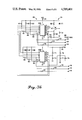
FIG. 3a-b comprises a schematic diagram of the device;
FIG. 4 comprises a schematic diagram of the fault control switch in combination with a typical electronically controlled fuel injection system;
FIG. 5 comprises a flow chart depicting certain operating characteristics of the device; and
FIG. 6 comprises a flow chart depicting certain operating characteristics of the device.
BEST MODE FOR CARRYING OUT THE INVENTION
Referring now to the drawings, and in particular to FIG. 1, the device can be seen as depicted generally by the numeral 10. The device (10) includes generally a fault detect and protection unit (11), a fault control switch (12), and a current sense unit (18). In this particular embodiment, the device (10) operates in conjunction with a control unit (13), an injector driver unit (14), a current control switch (16), an injector driver solenoid (17), a CAM position sense unit (19), and a power source (21). Control units, injector driver units, current control switches, injector solenoids, CAM position sense units, and power sources are well known in the art and could be provided for herein through use of any of a variety of components and systems. Therefore, no more detailed description or explanation need be set forth here.
It may be helpful to note at the outset that both the control unit (13) and the fault detect and protection unit (11) receive CAM position signals from the CAM position sense unit (19), and that both the injector driver unit (14) and the fault detect and protection unit (11) can receive current sense signals from the current sense unit (18).
Referring now to FIG. 2, the fault detect and protection unit (11) can be comprised of a microcomputer (20) such as the MC6801 as manufactured by Motorola, Inc. The microcomputer (20) has a control signal input for receiving control signals from the control unit and a CAM position sense input for receiving CAM position signals. The microcomputer (20) also includes a current sense unit input for receiving current sense unit information from the current sense unit (18) as may be obtained by comparing the voltage across a current sense resistor (23) with a reference signal from a reference unit (24) in a comparator (26).
The microcomputer (20) also provides a fault control switch output for issuing a fault control signal to the fault control switch (12) through a signal driver (27), and a data input/output port for providing fault data regarding fault conditions. With momentary reference to FIG. 1, this fault data signal can be provided to the control unit (13) via a fault data line (28) as may be desired.
Referring now to FIGS. 3a-b, a more detailed description of the fault detect and protection unit (11) will be provided.
The fault detect and protection unit (11) includes generally a microcomputer (20), a buffer (22) (as provided through use of a 74HC126), a signal driver (27) (as provided through use of a 5417), and two comparator integrated circuits (26a and 26b) (both as provided through use of LM2901's).
Pins 2 and 3 of the microcomputer (20) have a 4 megahertz crystal (31) connected therebetween. Pin 2 also connects to ground through a 22 picofarad capacitor (32) and pin 3 similarly connects to ground through a second 22 picofarad capacitor (33).
The VSS port (pin 1) connects to ground. The two VCC ports (pin 7 and 21) connect to a 5 volt VCC source (34), and to ground through a 0.1 microfarad capacitor (35). The NMI and IRQ ports (pins 4 and 5) are coupled together, and through a 3.3 K ohm resistor (36) to VCC (34).
The Timer In, Timer Out, and Serial Communications Clock ports (pins 8, 9 and 10) of the microcomputer (20) each connect to a 10K ohm pull up resistor (36, 37 and 38, respectively) and to the buffer (22) (pins 3, 6 and 8, respectively). The Serial Communications Output port (pin 12) connects to a 10K ohm pull up resistor (39) and to the fault data signal line (28) referred to above with respect to FIGS. 1 and 2.
A RESET line (41) connects to an 82 ohm 1/2 watt pull up resistor (42) and to the RESET port (pin 6) of the microcomputer (20).
Pins 31 through 37, as configured, comprise an input bus that connects to the comparators (26a and 26b) and to a clock input line (43) (as described in more detail below) to receive the current sense signals described above. Pins 24 through 29 comprise a non-multiplexed address bus that are configured to receive the control signals as transmitted by the control unit (13) to the injector driver unit (14) to cause its activation. Finally, pins 15 through 20 comprise input/output lines that are each connected to a 10K ohm pull up resistor (44 through 49, respectively) and to the input pins ( pins 1, 3, 5, 9, 11, and 13, respectively) of the signal driver (27) referred to above.
The buffer (22) referred to above has pin 14 connected to VCC (34) and to ground through a 0.1 microfarad capacitor (51). Pin 7 connects directly to ground. Pins 1, 4, 10 and 13 are coupled together and to pin 13 of one of the comparators (26b), which comparators will be described in more detail below. Finally, pin 2 connects to receive CAM PULSE signals from the CAM position sense unit (19) as generally referred to above.
The signal driver (27) has its input ports connected to the microcomputer (20) as described above. In addition, pin 7 connects to ground, and pin 14 connects to VCC (34) and to ground through a 0.1 microfarad capacitor (52). The output ports (pins 2, 4, 6, 8, 10, and 12) connect to the fault control switches (12) as described in more detail below and serve to provide the fault protect signal referred to above.
Referring now specifically to FIG. 3b, the comparators (26a and 26b) of the fault detect and protection unit (11) will be described in detail.
The first comparator (26a) has pins 7, 9 and 11 coupled through 1K ohm resistors (53, 54, and 56, respectively) to the current sense units (18) for receiving the current sense signals. These same ports (pins 7, 9 and 11) also connect through 18K ohm resistors (57, 58 and 59, respectively) to pins 1, 14, and 13, respectively.
Pins 1, 14, and 13 also connect to 6.8K ohm pull up resistors (61, 62 and 63, respectively) and to pins 37, 36, and 35 of the microcomputer (20). Pin 3 connects to VCC (34). Pins 5, 2, 4, and 12 connect to ground.
Referring now to the reference unit (24), pins 6, 8 and 10 are coupled together and connect: (a) through a 22 microfarad electrolytic capacitor (64) to a power ground (66); and (b) to the collector of a transistor (67).
The collector of this transistor (67) connects through a 390 ohm resistor (68) to the power ground (66). The emitter of this transistor (67) connects through a 4.7K ohm resistor (69) to VCC (34). The base of this transistor (67) connects to ground through a 5.6K ohm resistor (72) and to VCC through a 3.6 volt Zener diode (71).
With continued reference to FIG. 3b, the second comparator unit (26b) has pins 4, 6, and 8 connected to the collector of the above mentioned transistor (67). Pin 3 connects to VCC (34). Pin 12 connects to ground. Pin 10 connects to a voltage divider comprised of a 3.3K ohm resistor (73) and a grounded 2.2K ohm resistor (74). Pin 11 connects to another voltage divider network comprising a 2.2K ohm resistor (76) and a parallel coupled and grounded 3.3K ohm resistor (77) and a 180 picofarad capacitor (78). Pin 11 also connects to receive the RESET signal from the RESET line (41) referred to above. Pin 13 connects to the buffer (22) described above.
Pins 5, 7, and 9 connect through 1K ohm resistors (79, 80, and 81, respectively) to the current sense units (18) described below for receiving the current sense signals. In addition, pins 5, 7, and 9 connect through 18K ohm resistors (82, 83, and 84, respectively) to pins 2, 1, and 14 respectively. Pins 2, 1, and 14 also connect through 6.8K ohm pull up resistors (86, 87, and 88, respectively) and to pins 34, 33, and 32 of the microcomputer (20) referred to above.
So configured, current sense signals from the current sense units (18) can be compared in the comparators (26a and 26b) with reference signals from the reference unit (24), with the resulting comparator outputs being provided to the microcomputer (20). The microcomputer (20) also receives direct control signal inputs from the control unit (13), which control signals are also provided to the injector driver unit (14) (as depicted in FIG. 1). Finally, the microcomputer (20) receives engine revolution data in the form of CAM degree position information as received and transmitted through the buffer (22).
In turn, the microcomputer (20) can provide a fault protect signal to the fault control switches (12) through the signal driver unit (27), and can provide fault data signals to any desired location through the fault data line serial link (28).
Referring now to FIG. 4, the fault control switch (12) can be described. In ths embodiment, the fault control switch (12) can be provided through use of an MTM25N06 FET transistor (as manufactured by Motorola, Inc.) having its source and drain terminals connected in series with a fuel injector solenoid (17), and its gate coupled to receive the fault protect signals (OFF) as transmitted by the microcomputer (20). In addition, a 200K ohm resistor (91) connects the gate to a positive 10 volt source. So configured, the transistor (12) will allow current to pass through the solenoid (17) in accordance with the conductive state of the current control switch (16) (represented here as a transistor). Upon issuance of a fault protect signal, however, the transistor (12) will open with respect to its power terminals and disrupt the current flow through the solenoid (17) regardless of the conductive state of the current control switch (16).
The microcomputer (20) can be readily programmed to perform the functions described above. With reference to FIG. 5, a flow chart describing a general approach to these functions will now be delineated.
To begin, the microcomputer (20) will determine whether it is yet time to sample the fault status of the injector drivers (100). Any desired frequency for such periodic sampling can be selected as desired (the applicants have selected a sample rate of 1.3 milliseconds) to effectuate the desired performance criteria.
When the sampling time arrives, the microcomputer (20) will make a determination as to whether the engine rotation data in the form of CAM degrees information is in sync (101). If not, then no fault status inquiries should be made because any conclusions that result from such an inquiry would be suspect.
Presuming that the engine revolution data passes inspection, a second inquiry will be made to determine whether the engine revolutions per minute exceed some preselected minimum (102), such as 500 RPM. If they do not, then again fault status inquiries should be postponed because resulting conclusions could be unreliable.
Presuming this requirement to have been met or exceeded, the program may then calculate a specific CAM degrees increment representing the increase in CAM degrees from the last previous calculation (103). This information will be utilized elsewhere in the program. (A variety of ways are known in the art for calculating such information. The specific algorithm or technique utilized therefore need not be presented here, and for the sake of brevity will not be presented.) Following this, the microcomputer (20) can determine the fault status of the first injector driver circuit (104) in conjunction with the fault status subroutine discussed below. Upon concluding this inquiry, the next injector driver circuit can be similarly analyzed (106), until finally the last injector driver circuit has been inspected (107). In the particular embodiment described above with respect to FIG. 3a-b, up to six injector driver circuits can be monitored. The number of circuits monitored, of course, simply reflects a design consideration and will typically equal the number of combustion chambers in the engine to be controlled.
At the conclusion of this inquiry, the program can return to perform other functions or to repeat the sequence just described, as desired.
Referring now to FIG. 6, a flow chart describing a fault status inquiry as useable with any of the injector driver circuits will now be described.
At the outset, the microcomputer (20) will consider the control signal inputs to determine the presence or absence of control pulse signals for the injector driver circuit under consideration (111). In the absence of such a signal, the microcomputer (20) will determine whether the solenoid (17) has current flowing through it by referring to the current sense input for that injector driver (112). If current can be sensed, this represents a fault condition, and the microcomputer (20) will respond by open circuiting the solenoid circuit (113) as described above by appropriate manipulation of the fault control switch (12).
Following this, or presuming that current cannot be sensed, the microcomputer (20) will upgrade a "control pulse off" degrees count (114). This count represents a count of CAM degrees during which the control signal has been continuously absent. Following this incremental upgrade, the microcomputer (20) will then determine whether this accumulated count equals or exceeds some preselected maximum (116). If it does not, the subroutine will return the microcomputer (20) to its ordinary process. If, however, the accumulated count does exceed the preselected maximum, the microcomputer (20) will conclude that the control pulse has faulted "off" (117), and this conclusion can be appropriately transmitted through the fault data signal line (28) for diagnostic and maintenance purposes.
Referring back to the original decision block (111), if the microcomputer (20) senses the presence of the control pulse, the program will incrementally increase a "control pulse on" degrees count (118). This count comprises a count of the accumulated CAM degrees during which the control pulse has been continuously present. Following this incremental increase, the microcomputer (20) will determine whether this accumulated count equals or exceeds a preselected maximum (119). If it does, the microcomputer (20) will conclude that the control pulse has faulted "on" (121), and will respond by open circuiting the solenoid circuit (122) as described above through appropriate manipulation of the fault control switch (12).
Following this, or in the event that the "control pulse on" degrees count does not equal or exceed the preselected maximum, the microcomputer (20) will make a determination as to whether the solenoid has current flowing therethrough (123). If it does not, then the microcomputer (20) can conclude that the solenoid circuit has faulted "off" (124) and an appropriate fault data signal can be transmitted via the fault data signal line (28) for appropriate diagnostic and maintenance purposes. Following this, or presuming that the solenoid does have current flowing therethrough, the subroutine will return the microcomputer (20) to its primary routine.
Through use of the injector driver fault detect and protection device described above, an electronically controlled fuel injection system can be rendered safer and more reliable. The dangerous conditions that can result through an unrestricted admission of fuel into the combustion chambers of an engine can be halted upon detecting an inappropriate control signal input or actual current flow through the solenoid. Other fault conditions that do not present the hazards of unrestricted fuel flow are similarly sensed and information regarding these faults made available to further diagnostic and maintenance functions.
Those skilled in the art will recognize that many modifications and variations can be made with respect to the above described embodiment without departing from the spirit of the invention. Therefore, the scope of this invention should not be considered as being limited to the specific embodiment set forth, except insofar as the claims may contain specific limitations directed to such features.

Claims (19)

We claim:
1. In a fuel injection system having at least one fuel injection valve for use with an engine, at least one solenoid for controlling said fuel injection valve, a power line operably connected to said solenoid, control means for providing a control signal, injector driver means responsive to said control signal for providing a drive signal, and switch means having selectively variable conductive states and being responsive to said drive signal for selectively closing and opening said power line to thereby control said solenoid, an improvement comprising:
(a) current sense means for sensing current flow through said solenoid and for producing a current sense signal in response thereto;
(b) fault detect means for receiving said current sense signal and said control signal for providing a fault protect signal when said current sense means provides said current sense signal and said control means does not substantially simultaneously provide said control signal; and
(c) fault protect switch means responsive to said fault protect signal for preventing a flow of current through said solenoid.
2. The ir:provement of claim 1 wherein said fault protect switch means operates to selectively open and close said power line.
3. The improvement of claim 1 wherein said current sense means comprises a resistor.
4. The improvement of claim 3 wherein said resistor connects in series with said power line.
5. The improvement of claim 1 wherein said fault detect means further receives engine revolution data and functions to maintain a selective count related to said engine revolution data.
6. The improvement of claim 5 wherein said engine revolution data relates to CAM degrees.
7. The improvement of claim 5 wherein said fault detect means provides a fault data signal when said control signal has been absent longer than a predetermined count of said engine revolution data.
8. In a fuel injection system having at least one fuel injection valve for use with an engine, at least one solenoid for controlling said fuel injection valve, a power line operably connected to said solenoid, control means for providing a control signal, injector driver means responsive to said control signal for providing a drive signal, and switch means having selectively variable conductive states and being responsive to said drive signal for selectively closing and opening said power line to thereby control said solenoid, an improvement comprising:
(a) fault detect means for receiving;
(i) said control signal; and
(ii) engine revolution data from an engine used in conjunction with said fuel injection system; said fault detect means providing a fault protect signal when said control signal has been continuously in existence for too long in view of said engine revolution data; and
(b) fault protect switch means responsive to said fault protect signal for preventing a flow of current through said solenoid.
9. The improvement of claim 8 wherein said fault protect switch means functions to selectively open and close said power line.
10. The improvement of claim 8 wherein said engine revolution data relates to CAM degrees.
11. The improvement of claim 10 wherein said "too long" criteria relates to a preselected specific number of CAM degrees.
12. The improvement of claim 8 and further including current sense means for sensing current flow through said solenoid and for producing a current sense signal in response thereto.
13. The improvement of claim 12 wherein said fault detect means further receives said current sense signal, and functions to provide a fault data signal if said fault detect means senses that a control signal is present and no current is substantially simultaneously flowing through said solenoid.
14. In a fuel injection system having at least one fuel injection valve for use with an engine, at least one solenoid for controlling said fuel injection valve, a power line operably connected to said solenoid, control means for providing a control signal, injector driver means responsive to said control signal for providing a drive signal, and switch means having selectively variable conductive states and being responsive to said drive signal for selectively closing and opening said power line to thereby control said solenoid, an improvement comprising:
(a) current sense means for sensing current flow through said solenoid and for producing a current sense signal in response thereto;
(b) fault detect means for receiving:
(i) said current sense signal;
(ii) said control signal; and
(iii) engine revolution data; for providing
(i) a fault protect signal when said current sense means provides said current sense signal and said control means does not substantially simultaneously provide said control signal; and
(ii) a fault protect signal when said control signal has been in existence for too long in view of said engine revolution data; and
(c) fault protect switch means responsive to said fault protect signal for preventing a flow of current through said solenoid.
15. The improvement of claim 14 wherein said fault detect means maintains a count related to said engine revolution data.
16. The improvement of claim 15 wherein said engine revolution data relates to CAM degrees.
17. The improvement of claim 16 wherein said "too long" criteria relates to a specific number of said CAM degrees.
18. The improvement of claim 16 wherein said fault detect means provides a fault data signal when said control signal has been absent greater than a predetermined count of said CAM degrees.
19. The improvement of claim 14 wherein said fault detect means provides a fault data signal if said fault detect means senses that said control signal is present and that substantially simultaneously therewith no current flows through said solenoid.
US06/722,534 1985-04-12 1985-04-12 Injector driver fault detect and protection device Expired - Lifetime US4589401A (en)

Priority Applications (4)

Application Number Priority Date Filing Date Title
US06/722,534 US4589401A (en) 1985-04-12 1985-04-12 Injector driver fault detect and protection device
PCT/US1986/000213 WO1986006138A1 (en) 1985-04-12 1986-01-30 Injector driver fault detect and protection device
JP61501079A JPS62503042A (en) 1985-04-12 1986-01-30 Injector driver fault detection and protection device
EP19860901238 EP0217812A4 (en) 1985-04-12 1986-01-30 Injector driver fault detect and protection device.

Applications Claiming Priority (1)

Application Number Priority Date Filing Date Title
US06/722,534 US4589401A (en) 1985-04-12 1985-04-12 Injector driver fault detect and protection device

Publications (1)

Publication Number Publication Date
US4589401A true US4589401A (en) 1986-05-20

Family

ID=24902255

Family Applications (1)

Application Number Title Priority Date Filing Date
US06/722,534 Expired - Lifetime US4589401A (en) 1985-04-12 1985-04-12 Injector driver fault detect and protection device

Country Status (4)

Country Link
US (1) US4589401A (en)
EP (1) EP0217812A4 (en)
JP (1) JPS62503042A (en)
WO (1) WO1986006138A1 (en)

Cited By (40)

* Cited by examiner, † Cited by third party
Publication number Priority date Publication date Assignee Title
US4696277A (en) * 1985-11-04 1987-09-29 Nippondenso Co., Ltd. Engine alarm system
EP0249448A1 (en) * 1986-06-09 1987-12-16 Mitsubishi Denki Kabushiki Kaisha Defect detector circuit for inductive load driving circuit
WO1988000286A1 (en) * 1986-06-30 1988-01-14 Robert Bosch Gmbh Monitoring device for an electronic control system in a motor vehicle
US4727835A (en) * 1985-03-04 1988-03-01 Toyota Jidosha Kabushiki Kaisha Fuel injection device in diesel engine
US4736267A (en) * 1986-11-14 1988-04-05 Motorola, Inc. Fault detection circuit
WO1988005131A1 (en) * 1986-12-24 1988-07-14 Keldan Industries Limited Solenoid injector monitor
US4782809A (en) * 1987-11-19 1988-11-08 Motorola, Inc. Fuel injector with electronic control circuit
EP0309753A1 (en) * 1987-09-30 1989-04-05 Siemens Aktiengesellschaft Method for monitoring an inductive load
US4862866A (en) * 1987-08-25 1989-09-05 Marelli Autronica S.P.A. Circuit for the piloting of inductive loads, particularly for operating the electro-injectors of a diesel-cycle internal combustion engine
EP0358972A1 (en) * 1988-09-14 1990-03-21 MARELLI AUTRONICA S.p.A. An electrical circuit, particularly an electronic power circuit for motor vehicle injection systems, with a function for the detection and diagnosis of faults, and method related thereto
US4920939A (en) * 1989-02-27 1990-05-01 Ford Motor Company Position sensor monitoring system
US4930481A (en) * 1988-07-27 1990-06-05 Mitsubishi Denki Kabushiki Kaisha Engine control apparatus
US4932246A (en) * 1989-02-22 1990-06-12 Motorola, Inc. Diagnostic fault test system and circuit
DE4004427A1 (en) * 1989-02-22 1990-08-23 Motorola Inc Diagnostic fault test system and circuit
EP0429406A1 (en) * 1989-11-07 1991-05-29 MAGNETI MARELLI S.p.A. A circuit for interfacing between a microprocessor and a plurality of power stages, particularly for controlling electro-injectors
EP0448219A1 (en) * 1990-03-17 1991-09-25 Eaton Corporation Transmission system solenoid controlled actuator fault detection system and method
US5063516A (en) * 1989-08-21 1991-11-05 Ford Motor Company Smart power driver system for a motor vehicle
EP0464731A2 (en) * 1990-06-29 1992-01-08 Klöckner-Humboldt-Deutz Aktiengesellschaft Control apparatus for an electromagnetic valve
US5214558A (en) * 1991-10-25 1993-05-25 International Business Machines Corporation Chopper drive control circuit
US5251091A (en) * 1990-06-18 1993-10-05 Aisin Aw Co., Ltd. Solenoid driving circuit for automatic transmission
US5383086A (en) * 1991-12-05 1995-01-17 Robert Bosch Gmbh System and method for triggering an inductive consumer
US5461563A (en) * 1992-09-04 1995-10-24 Mitsubishi Denki Kabushiki Kaisha Non-stage transmission control system
US5469825A (en) * 1994-09-19 1995-11-28 Chrysler Corporation Fuel injector failure detection circuit
US5687694A (en) * 1995-02-02 1997-11-18 Sanshin Kogyo Kabushiki Kaisha Engine control
DE4042519C2 (en) * 1989-02-22 2000-11-09 Motorola Inc Diagnostic fault test system and circuit
WO2002010570A1 (en) * 2000-07-28 2002-02-07 Siemens Aktiengesellschaft Electronic circuit configuration and corresponding method for controlling actuators such as valves or injectors
EP1179669A1 (en) * 2000-08-04 2002-02-13 MAGNETI MARELLI POWERTRAIN S.p.A. Method for the control of an injector in an internal combustion engine
US6469885B1 (en) * 2000-02-16 2002-10-22 Impact Devices Incorporated Power saving circuit for solenoid driver
EP1393957A2 (en) * 2002-08-27 2004-03-03 Toyoda Koki Kabushiki Kaisha Electrical load controlling device
US20050051139A1 (en) * 2003-03-12 2005-03-10 Todd Slater Methods and systems of diagnosing fuel injection system error
US20060224338A1 (en) * 2005-03-29 2006-10-05 Siemens Ag Method and device for verifying an electrical coupling state of an inductive load
US20060249121A1 (en) * 2005-05-09 2006-11-09 Honeywell International, Inc. Valve control method and circuitry for power generation systems
DE4418538B4 (en) * 1994-05-27 2007-10-18 Robert Bosch Gmbh Circuit arrangement for power supply for switchable loads
US20100199752A1 (en) * 2009-02-06 2010-08-12 Gm Global Technology Operations, Inc. Injector control performance diagnostic systems
US20110001459A1 (en) * 2008-02-01 2011-01-06 Continental Automotive Gmbh Circuit arrangement for controlling an inductive load
CN102182603A (en) * 2011-05-24 2011-09-14 浙江大学 Fault diagnosis device and method for high-pressure common-rail fuel injection system
US20110301772A1 (en) * 2010-06-07 2011-12-08 Zuercher Joseph C Protection, monitoring or indication apparatus for a direct current electrical generating apparatus or a plurality of strings
CN102410122A (en) * 2011-10-25 2012-04-11 浙江大学 Fault diagnosis device and method for vehicle solenoid valve
CN102477927A (en) * 2010-11-24 2012-05-30 联创汽车电子有限公司 Fault simulating and driving current collecting circuit of oil sprayer of automobile engine
US20150354522A1 (en) * 2014-06-05 2015-12-10 Caterpillar Inc. System and method for detecting short-to-ground fault

Families Citing this family (5)

* Cited by examiner, † Cited by third party
Publication number Priority date Publication date Assignee Title
US4771755A (en) * 1986-01-22 1988-09-20 Honda Giken Kogyo K.K. Abnormality detecting method for air-fuel ratio control system for internal combustion engines
US4875409A (en) * 1987-07-01 1989-10-24 Printronix, Inc. Magnetic print hammer actuator protection circuit
JPH01169159A (en) * 1987-12-25 1989-07-04 Aisin Aw Co Ltd Electronic control unit for automatic transmission
JPH02228572A (en) * 1989-03-02 1990-09-11 Fuji Heavy Ind Ltd Diagnostic apparatus for injector
JPH0826910B2 (en) * 1989-06-30 1996-03-21 三菱電機株式会社 Short circuit ground fault detection device for electromagnetic clutch for vehicle

Citations (6)

* Cited by examiner, † Cited by third party
Publication number Priority date Publication date Assignee Title
US4287565A (en) * 1978-09-29 1981-09-01 Robert Bosch Gmbh Monitoring system for program controlled apparatus
US4310889A (en) * 1977-10-19 1982-01-12 Hitachi, Ltd. Apparatus for electronically controlling internal combustion engine
US4375074A (en) * 1980-08-08 1983-02-22 Reliance Electric Company Dual-mode transistor turn-off
US4375073A (en) * 1980-06-16 1983-02-22 Reliance Electric Company Dual-monitoring protection circuit for switching transistor
US4471739A (en) * 1982-08-13 1984-09-18 Honda Giken Kogyo Kabushiki Kaisha Fuel injection control method for a multi-cylinder internal combustion engine, having a fail safe function for abnormality in cylinder-discriminating means
US4541386A (en) * 1983-06-30 1985-09-17 Honda Giken Kogyo Kabushiki Kaisha Abnormality detecting apparatus for means for sensing operating parameters of an internal combustion engine

Family Cites Families (6)

* Cited by examiner, † Cited by third party
Publication number Priority date Publication date Assignee Title
GB1244925A (en) * 1968-10-23 1971-09-02 Brevete Et D Etudes S I B E So Improvements in or relating to fuel feed devices for internal combustion engines
DE3124724C2 (en) * 1980-08-11 1984-08-30 VEB Wissenschaftlich-Technisches Zentrum Automobilbau Karl-Marx-Stadt, DDR 9000 Karl-Marx-Stadt Circuit arrangement for putting electromagnetic injection nozzles out of operation in electronically controlled fuel injection systems for internal combustion engines
JPS5932631A (en) * 1982-08-17 1984-02-22 Honda Motor Co Ltd Fuel pump controlling apparatus for internal combustion engine
JPS5952306A (en) * 1982-09-18 1984-03-26 Honda Motor Co Ltd Abnormality discriminating method of electronic controller
US4479161A (en) * 1982-09-27 1984-10-23 The Bendix Corporation Switching type driver circuit for fuel injector
DE3238752C2 (en) * 1982-10-20 1986-11-13 Robert Bosch Gmbh, 7000 Stuttgart Method and device for self-monitoring of the control unit of electrical injection systems for internal combustion engines

Patent Citations (6)

* Cited by examiner, † Cited by third party
Publication number Priority date Publication date Assignee Title
US4310889A (en) * 1977-10-19 1982-01-12 Hitachi, Ltd. Apparatus for electronically controlling internal combustion engine
US4287565A (en) * 1978-09-29 1981-09-01 Robert Bosch Gmbh Monitoring system for program controlled apparatus
US4375073A (en) * 1980-06-16 1983-02-22 Reliance Electric Company Dual-monitoring protection circuit for switching transistor
US4375074A (en) * 1980-08-08 1983-02-22 Reliance Electric Company Dual-mode transistor turn-off
US4471739A (en) * 1982-08-13 1984-09-18 Honda Giken Kogyo Kabushiki Kaisha Fuel injection control method for a multi-cylinder internal combustion engine, having a fail safe function for abnormality in cylinder-discriminating means
US4541386A (en) * 1983-06-30 1985-09-17 Honda Giken Kogyo Kabushiki Kaisha Abnormality detecting apparatus for means for sensing operating parameters of an internal combustion engine

Cited By (61)

* Cited by examiner, † Cited by third party
Publication number Priority date Publication date Assignee Title
US4727835A (en) * 1985-03-04 1988-03-01 Toyota Jidosha Kabushiki Kaisha Fuel injection device in diesel engine
US4696277A (en) * 1985-11-04 1987-09-29 Nippondenso Co., Ltd. Engine alarm system
AU581369B2 (en) * 1986-06-09 1989-02-16 Mitsubishi Denki Kabushiki Kaisha Defect detector circuit for inductive load driving circuit
EP0249448A1 (en) * 1986-06-09 1987-12-16 Mitsubishi Denki Kabushiki Kaisha Defect detector circuit for inductive load driving circuit
WO1988000286A1 (en) * 1986-06-30 1988-01-14 Robert Bosch Gmbh Monitoring device for an electronic control system in a motor vehicle
US4736267A (en) * 1986-11-14 1988-04-05 Motorola, Inc. Fault detection circuit
WO1988005131A1 (en) * 1986-12-24 1988-07-14 Keldan Industries Limited Solenoid injector monitor
US4862866A (en) * 1987-08-25 1989-09-05 Marelli Autronica S.P.A. Circuit for the piloting of inductive loads, particularly for operating the electro-injectors of a diesel-cycle internal combustion engine
EP0309753A1 (en) * 1987-09-30 1989-04-05 Siemens Aktiengesellschaft Method for monitoring an inductive load
US4782809A (en) * 1987-11-19 1988-11-08 Motorola, Inc. Fuel injector with electronic control circuit
US4930481A (en) * 1988-07-27 1990-06-05 Mitsubishi Denki Kabushiki Kaisha Engine control apparatus
US5173832A (en) * 1988-09-14 1992-12-22 Marelli Autronica Spa Electrical circuit, particularly an electronic power circuit for motor vehicle injection systems, with a function for the detection and diagnosis of faults, and the related method
EP0358972A1 (en) * 1988-09-14 1990-03-21 MARELLI AUTRONICA S.p.A. An electrical circuit, particularly an electronic power circuit for motor vehicle injection systems, with a function for the detection and diagnosis of faults, and method related thereto
DE4004427A1 (en) * 1989-02-22 1990-08-23 Motorola Inc Diagnostic fault test system and circuit
US4932246A (en) * 1989-02-22 1990-06-12 Motorola, Inc. Diagnostic fault test system and circuit
DE4042519C2 (en) * 1989-02-22 2000-11-09 Motorola Inc Diagnostic fault test system and circuit
US4920939A (en) * 1989-02-27 1990-05-01 Ford Motor Company Position sensor monitoring system
US5063516A (en) * 1989-08-21 1991-11-05 Ford Motor Company Smart power driver system for a motor vehicle
EP0429406A1 (en) * 1989-11-07 1991-05-29 MAGNETI MARELLI S.p.A. A circuit for interfacing between a microprocessor and a plurality of power stages, particularly for controlling electro-injectors
EP0448219A1 (en) * 1990-03-17 1991-09-25 Eaton Corporation Transmission system solenoid controlled actuator fault detection system and method
AU651334B2 (en) * 1990-03-17 1994-07-21 Eaton Corporation Transmission system solenoid controlled actuator fault detection system and method
US5251091A (en) * 1990-06-18 1993-10-05 Aisin Aw Co., Ltd. Solenoid driving circuit for automatic transmission
EP0464731A2 (en) * 1990-06-29 1992-01-08 Klöckner-Humboldt-Deutz Aktiengesellschaft Control apparatus for an electromagnetic valve
EP0464731A3 (en) * 1990-06-29 1993-03-31 Kloeckner-Humboldt-Deutz Aktiengesellschaft Control apparatus for an electromagnetic valve
US5214558A (en) * 1991-10-25 1993-05-25 International Business Machines Corporation Chopper drive control circuit
US5383086A (en) * 1991-12-05 1995-01-17 Robert Bosch Gmbh System and method for triggering an inductive consumer
US5461563A (en) * 1992-09-04 1995-10-24 Mitsubishi Denki Kabushiki Kaisha Non-stage transmission control system
DE4418538B4 (en) * 1994-05-27 2007-10-18 Robert Bosch Gmbh Circuit arrangement for power supply for switchable loads
US5469825A (en) * 1994-09-19 1995-11-28 Chrysler Corporation Fuel injector failure detection circuit
US5687694A (en) * 1995-02-02 1997-11-18 Sanshin Kogyo Kabushiki Kaisha Engine control
US6469885B1 (en) * 2000-02-16 2002-10-22 Impact Devices Incorporated Power saving circuit for solenoid driver
WO2002010570A1 (en) * 2000-07-28 2002-02-07 Siemens Aktiengesellschaft Electronic circuit configuration and corresponding method for controlling actuators such as valves or injectors
US6748929B2 (en) 2000-07-28 2004-06-15 Siemens Aktiengesellschaft Electronic circuit configuration and corresponding method for controlling actuators such as valves or injectors
EP1179669A1 (en) * 2000-08-04 2002-02-13 MAGNETI MARELLI POWERTRAIN S.p.A. Method for the control of an injector in an internal combustion engine
US6601567B2 (en) 2000-08-04 2003-08-05 Magneti Marelli Powertrain S.P.A. Method for the control of an injector in an internal combustion engine
US7006899B2 (en) 2002-08-27 2006-02-28 Toyoda Koki Kabushiki Kaisha Electrical load controlling device
EP1393957A3 (en) * 2002-08-27 2004-04-28 Toyoda Koki Kabushiki Kaisha Electrical load controlling device
US20040044459A1 (en) * 2002-08-27 2004-03-04 Toyoda Koki Kabushiki Kaisha Electrical load controlling device
EP1747932A3 (en) * 2002-08-27 2007-04-04 Toyoda Koki Kabushiki Kaisha Electrical load controlling device
EP1393957A2 (en) * 2002-08-27 2004-03-03 Toyoda Koki Kabushiki Kaisha Electrical load controlling device
US20050051139A1 (en) * 2003-03-12 2005-03-10 Todd Slater Methods and systems of diagnosing fuel injection system error
US7252072B2 (en) 2003-03-12 2007-08-07 Cummins Inc. Methods and systems of diagnosing fuel injection system error
US20060224338A1 (en) * 2005-03-29 2006-10-05 Siemens Ag Method and device for verifying an electrical coupling state of an inductive load
US7486080B2 (en) * 2005-03-29 2009-02-03 Siemens Aktiengesellschaft Method and device for verifying an electrical coupling state of an inductive load
US20060249121A1 (en) * 2005-05-09 2006-11-09 Honeywell International, Inc. Valve control method and circuitry for power generation systems
US7330345B2 (en) 2005-05-09 2008-02-12 Honeywell International, Inc. Valve control method for circuitry for power generation systems
US8360032B2 (en) * 2008-02-01 2013-01-29 Continental Automotive Gmbh Circuit arrangement for controlling an inductive load
US20110001459A1 (en) * 2008-02-01 2011-01-06 Continental Automotive Gmbh Circuit arrangement for controlling an inductive load
US20100199752A1 (en) * 2009-02-06 2010-08-12 Gm Global Technology Operations, Inc. Injector control performance diagnostic systems
DE102010006568B4 (en) 2009-02-06 2018-04-26 GM Global Technology Operations LLC (n. d. Ges. d. Staates Delaware) Diagnostic systems for the behavior of a single-injection device control
US7856867B2 (en) * 2009-02-06 2010-12-28 Gm Global Technology Operations, Inc. Injector control performance diagnostic systems
US20110301772A1 (en) * 2010-06-07 2011-12-08 Zuercher Joseph C Protection, monitoring or indication apparatus for a direct current electrical generating apparatus or a plurality of strings
US8837097B2 (en) * 2010-06-07 2014-09-16 Eaton Corporation Protection, monitoring or indication apparatus for a direct current electrical generating apparatus or a plurality of strings
CN102477927A (en) * 2010-11-24 2012-05-30 联创汽车电子有限公司 Fault simulating and driving current collecting circuit of oil sprayer of automobile engine
CN102477927B (en) * 2010-11-24 2013-11-06 联创汽车电子有限公司 Fault simulating and driving current collecting circuit of oil sprayer of automobile engine
CN102182603A (en) * 2011-05-24 2011-09-14 浙江大学 Fault diagnosis device and method for high-pressure common-rail fuel injection system
CN102410122A (en) * 2011-10-25 2012-04-11 浙江大学 Fault diagnosis device and method for vehicle solenoid valve
US20150354522A1 (en) * 2014-06-05 2015-12-10 Caterpillar Inc. System and method for detecting short-to-ground fault
CN105319473A (en) * 2014-06-05 2016-02-10 卡特彼勒公司 System and method for detecting short-to-ground fault
US9429126B2 (en) * 2014-06-05 2016-08-30 Caterpillar Inc. System and method for detecting short-to-ground fault
CN105319473B (en) * 2014-06-05 2019-05-28 卡特彼勒公司 System and method for detecting ground short circuit failure

Also Published As

Publication number Publication date
JPS62503042A (en) 1987-12-03
EP0217812A4 (en) 1987-11-09
WO1986006138A1 (en) 1986-10-23
EP0217812A1 (en) 1987-04-15

Similar Documents

Publication Publication Date Title
US4589401A (en) Injector driver fault detect and protection device
US5047944A (en) Vehicle control apparatus including abnormality detection
US6230094B1 (en) Electronic control system and method having monitor program
US5092305A (en) Apparatus and method for providing an alternative fuel system for engines
US4422420A (en) Method and apparatus for fuel control in fuel injected internal combustion engines
US4912382A (en) Fail safe monitoring apparatus and method
US6601015B1 (en) Embedded datalogger for an engine control system
US20020193935A1 (en) Intake air quantity control system for internal combustion engine
CA1283190C (en) Temperature controller for a transport refrigeration system
US20080092826A1 (en) Combustion Control Device
JPH0588924A (en) Multicomputer system of automobile
US5182755A (en) Malfunction checking system for controller
US4896276A (en) Self-diagnosis device and process for a micro-computer control system for a motor-vehicle internal combustion engine
US6845315B2 (en) Engine air-intake control device and engine air-intake control method
US5130930A (en) Diagnostic device for vehicle engine analysis
US6807477B2 (en) Electronic control system and method having monitor program monitoring function
JPH0674087A (en) Electric control device with backup memory
US5138833A (en) Converter overtemperature protection system and method
US5806015A (en) Automotive controller
KR100188723B1 (en) The safety apparatus for engine control device of idle speed actuator
KR100196352B1 (en) Obstacle-check control method of car speed sensor installed in diesel engine vehicle
KR0138806Y1 (en) Auto-transmission control with malfunction of location detection for a throttle valve
JPH068288Y2 (en) Engine fuel controller
JPH0311410Y2 (en)
KR0154023B1 (en) Engine controller of automobile

Legal Events

Date Code Title Description
AS Assignment

Owner name: MOTOROLA INC., SCHAUMBURG, ILLINOIS A CORP OF DE

Free format text: ASSIGNMENT OF ASSIGNORS INTEREST.;ASSIGNORS:KARIM, FRANK;FRANK, HOWARD L.;HOPMAN, NICHOLAS C.;REEL/FRAME:004420/0388

Effective date: 19850412

Owner name: MOTOROLA INC., A CORP OF DE, ILLINOIS

Free format text: ASSIGNMENT OF ASSIGNORS INTEREST;ASSIGNORS:KARIM, FRANK;FRANK, HOWARD L.;HOPMAN, NICHOLAS C.;REEL/FRAME:004420/0388

Effective date: 19850412

STCF Information on status: patent grant

Free format text: PATENTED CASE

FPAY Fee payment

Year of fee payment: 4

FEPP Fee payment procedure

Free format text: PAYOR NUMBER ASSIGNED (ORIGINAL EVENT CODE: ASPN); ENTITY STATUS OF PATENT OWNER: LARGE ENTITY

FPAY Fee payment

Year of fee payment: 8

FPAY Fee payment

Year of fee payment: 12