US4597707A - Automatic operating palletizer - Google Patents
Automatic operating palletizer Download PDFInfo
- Publication number
- US4597707A US4597707A US06/642,032 US64203284A US4597707A US 4597707 A US4597707 A US 4597707A US 64203284 A US64203284 A US 64203284A US 4597707 A US4597707 A US 4597707A
- Authority
- US
- United States
- Prior art keywords
- support beam
- product
- palletizer
- automatically operating
- horizontal
- Prior art date
- Legal status (The legal status is an assumption and is not a legal conclusion. Google has not performed a legal analysis and makes no representation as to the accuracy of the status listed.)
- Expired - Lifetime
Links
Images


Classifications
-
- B—PERFORMING OPERATIONS; TRANSPORTING
- B65—CONVEYING; PACKING; STORING; HANDLING THIN OR FILAMENTARY MATERIAL
- B65G—TRANSPORT OR STORAGE DEVICES, e.g. CONVEYORS FOR LOADING OR TIPPING, SHOP CONVEYOR SYSTEMS OR PNEUMATIC TUBE CONVEYORS
- B65G61/00—Use of pick-up or transfer devices or of manipulators for stacking or de-stacking articles not otherwise provided for
-
- Y—GENERAL TAGGING OF NEW TECHNOLOGICAL DEVELOPMENTS; GENERAL TAGGING OF CROSS-SECTIONAL TECHNOLOGIES SPANNING OVER SEVERAL SECTIONS OF THE IPC; TECHNICAL SUBJECTS COVERED BY FORMER USPC CROSS-REFERENCE ART COLLECTIONS [XRACs] AND DIGESTS
- Y10—TECHNICAL SUBJECTS COVERED BY FORMER USPC
- Y10S—TECHNICAL SUBJECTS COVERED BY FORMER USPC CROSS-REFERENCE ART COLLECTIONS [XRACs] AND DIGESTS
- Y10S414/00—Material or article handling
- Y10S414/10—Associated with forming or dispersing groups of intersupporting articles, e.g. stacking patterns
- Y10S414/116—Associated with forming or dispersing groups of intersupporting articles, e.g. stacking patterns including control for pattern of group
Definitions
- the present invention relates to package palletizers and, more particularly, to an automatically operating palletizer.
- Another object of the present invention is to provide a light weight automatically operating palletizer which is relatively simple to operate and to "teach" patterns.
- a further object of the present invention is to provide an automatically operating palletizer which will move individual packages from one pickup plurality to a plurality of predetermined positions in space in accordance with a desired palletizing pattern, using a minimum of movement.
- Yet another object of the present invention is to provide an automatically operating palletizer which is simple in construction, durable in operation and faster in its plurality placement cycles.
- an automatically operating palletizer which consists of a support frame and an independent, fixed and stationary vertical support column formed of lightweight stainless steel members.
- the column is formed of six generally rectangular hollow beams that are welded together to form an integral structure having a relatively square outline.
- This structure has exceedingly high strength, despite its light-weight construction, because of the plurality of internal webs formed by the beam elements therein giving the column a honeycombed type structure.
- a first horizontal support beam is slidably mounted on the vertical support column and a second horizontal beam, referred to hereinafter as the product support beam and extends perpendicularly thereto.
- the product support beam is mounted to slide relative to the horizontal support beam and moves witn the horizontal support beam in a vertical direction relative to the support column.
- a product carrier and/or pickup head is slidably mounted on the product support beam for movement along its length.
- Drive means are provided on the support column, the horizontal support beam, and the product support beam for moving the horizontal support beam, product support beam, and carrier through multiple positions so that the carrier can move from a variable pickup position to any of a plurality of other positions within a predetermined three dimensional volume in order to stack packages on a pallet or the like.
- the palletizer of the invention being formed of lightweight stainless steel, has multiple advantages. For example, it can be used in humid areas and for food handling, whereas previously proposed systems cannot be used in this way. In addition, because of its lightweight the device has relatively low maintenance and requires no painting. It is formed in a relatively compact construction and thereby requires low power for operation. Indeed, the device of the invention will have a power consumption of no more than 1200 watts, 110 volts, making it the lowest power consuming palletizer presently on the market. This results from the fact that smaller motors can be used to operate the device as compared to the prior art structures. Such low current requirements also make the device safe for humans to operate, since the current supply is insufficient to cause serious harm in the event of an accident.
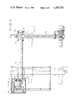
- FIG. 1 is a perspective view of an automatically operating palletizer constructed in accordance with the present invention
- FIG. 2 is a top plan view of the palletizer shown in FIG. 1;
- FIG. 3 is a side elevational view of the palletizer
- FIG. 4 is an enlarged side view of the mounting carriage for the horizontal support beam on the vertical support column of the device
- FIG. 5 is a sectional view taken along line 5--5 of FIG. 4;
- FIG. 6 is a sectional view taken along line 6--6 of FIG. 5;
- FIG. 7 is a top plan view of the mounting carriage for the product support beam on the horizontal support beam;
- FIG. 8 is a sectional view taken along line 8--8 of FIG. 9;
- FIG. 9 is a top plan view of the carriage arrangement for the product carrier on the product support beam.
- FIG. 10 is a side view of the carriage arrangement shown in FIG. 9, but with the carrier platform moved 90° into the dotted line position shown in FIG. 9;
- FIG. 10a is a sectional view of the product support beam taken along line 10a--10a of FIG. 10;
- FIG. 11 is a sectional view of one of the motor assemblies, for example used to drive the product support beam on the horizontal support beam.
- the palletizer includes a support frame 12 having an independent, fixed and stationary vertical support column 14 on which a horizontally extending support beam 16 is slidably mounted for vertical movement.
- a product support beam 18 is slidably mounted on beam 16 and extends perpendicularly to beam 16.
- the product support beam 18 is adapted to be moved, as described hereinafter, along the length of beam 16.
- a product carrier or pick-up head 20 is slidably mounted on product support beam 18 and can be driven along the length of that beam to any of a plurality of predetermined positions.
- Pickup head 20 has a clamp arrangement which enables it to pickup individual packages 22 from a conveyor 24 at the end of a product packaging line.
- the palletizer operates to lift the package from conveyor 24 and move it onto a pallet 26 in accordance with a predetermined and preprogrammed stacking pattern. While cartons 22 are ilIustrated in the drawing as being stacked, the palletizer can also be used to stack bags, sacks, drums, cans or the like.
- the product carrier or pickup head 20 can pivot through 90° from the position shown in FIG. 1, wherein it extends generally parallel to product support beam 18, to a position perpendicular thereto. As a result the packages can be stacked in one of two positions in order to interlock the packages in accordance witn common palletizing procedures.
- head 20 By using a larger ram 112, described hereinafter, having a larger rod, head 20 can be made to pivot through 180° if necessary.
- Palletizer 10 includes an automatic control system 28 which is preprogrammed, and reprogrammable in order to permit the operator to determine the desired stacking pattern.
- the control system is of the computerized numerical control type, such as is commonly used in machine tool centers wherein accurate positioning of tools in three dimensions is required.
- the programming therefore, is modified for this specific application, but the specific programming of these controls does not form any part of this invention and would be within the skill of those in the art of computerized numerical control systems.
- applicant is the first to conceive of the use of computerized numerical control systems for palletizing arrangements.
- palletizer support column 14 is housed within an outer casing 30 which shields the various moving parts for driving the horizontal support beam 16 in a vertical direction.
- Beam 16 has an inner end 32 which is mounted on, and rigidly secured to, a generally square carriage or sleeve 34 which is slidably mounted on support column 14.
- the carriage has a series of roller bearing structures 36 at two diagonally opposed corners which permit the carriage to roll vertically on the outer surface of column 14.
- These rollers are arranged on at least two of the diagonally opposed corners, of the carriage as shown in FIG. 6, which will bear the weight of the cantilevered beam 16.
- the roller can be located in each of its four corners.
- column 14 is actually formed of six rectangular beams or tubes 38.
- these beams are two-by-four stainless steel beams welded together at spaced locations along their length in the pattern illustrated in FIG. 6 to provide support column 14 with a square outer periphery.
- This configuration of the individual two-by-four stainless steel beams provides a relatively rigid high strength column, even though lightweight stainless steel is used. This is the result of the numerous internal webs formed in the column by these hollow beams providing the column with a form of "honeycomb" internal reinforcing structure.
- the carriage 34 is moved vertically relative to column 14 by a chain drive system which includes a counterweight 40 for balancing the weight of support beam 16 and the other structures mounted thereon with respect to the center line of the column.
- Counterweight 40 is connected by a first pair of drive chains 42, which pass from the top of the counterweight over a pair of sprockets 44, to points of connection on carriage 34.
- An additional drive chain 46 is connected between the lower end of the counterweight 40, over a lower pair of sprockets 48 on frame 12, to the back end 50 of the support beam 16 or carriage 34.
- This double chain arrangement provides a closed loop drive for the support beam so that the drive to the beam is balanced and the beam remains in a horizontal position during movement on the support column.
- the chains 42 are driven by a motor 52 mounted on the top of column 14 and connected to one of the pairs of sprockets 44 as seen in FIG. 5.
- connection of at least one of the chains 42 to carriage 34 is through a brake latch arrangement 54 which assures that the horizontal support beam will be stopped in a position spaced above the floor in the event chains 42 should break.
- the other chain is connected directly to carriage 34, although it could also be connected through an identical brake lock.
- Brake lock 54 includes a latch 56 pivotally mounted by a pivot pin 58 on the side of carriage 14, adjacent beam 16.
- the lower end of latch 56 includes a stop toe 60 which is adapted to pass through an opening 62 formed in carriage 36.
- Latch 56 is weighted such that when the tension on chains 42 is relieved, the latch will automaticaly pivot from the solid line position illustrated in FIG. 4 to the dotted line position, to move toe 60 closer to column 14.
- the latter has, on the side thereof opposite counterweight 40, a series of bars or stops 64 (only three of which are shown in FIG. 4) secured thereto and positioned to engage toe 60 should latch 56 move into the dotted line position of FIG. 4.
- the motor 52 which drives chains 42 is an electric motor having a low power consumption requirement. It is under the control of the computerized numerical control system 28 so that the column 16 is accurately moved vertically in space by the motor to any one of a multiplicity of positions between the two extreme upper and lower positions shown respectively in dotted and solid lines in FIG. 3.
- Product support beam 18 is slidably mounted on the horizontal support beam 16 by a carriage 70 rigidly secured, by welding or the like, to beam 18.
- This carriage is a generally square sleeve having a plurality of guide roller structures 72 located at its four corners to permit the carriage to roll along the surface of the support beam.
- the horizontal support beam, 16, as seen in FIG. 5, is formed of four rectangular two-by-four stainless steel beams 38, of the same size and construction as the beams 38 which form the vertical column. In this case, the four beams are arrayed as shown in FIG. 8 to form a generally square periphery for support beam 16. Again, because of the plurality of the internal webs formed by this construction, the beam will have substantial strength although formed of lightweight stainless steel.
- product support beam 18 is securely mounted on the upper side of carriage 70.
- the carriage is driven along the length of horizontal support beam 16 by an electric motor 75 which is mounted on carriage 70 in any convenient manner.
- the driveshaft 76 of motor 75 has a pinion 78 splined thereto. This pinion is in driving engagement with a longitudinally extending rack 80 rigidly secured to the lower surface of support beam 16.
- motor 75 When operated, motor 75 will turn pinion 78 against rack 80 and cause the carriage to slide or roll along support beam 16.
- This motor as seen in FIG. 11, has an optical encoder 82 associated therewith, as does the drive motor 52 and the drive motor for the carriage mounting the carrier on the product support beam 18.
- the optical encoder is of conventional known construction, and serves to provide a continuous signal to the computerized numerical control system 28 thus advising that system of the precise location in space at which the member it is driving is located.
- the control system can control operation of the motor 75 (and the other electric motors in the palletizer) to precisely locate the carrier or pickup head 20 to pick up a package 22 from conveyor 24 and move it to the desired location in space at which it is deposited on pallet 26.
- head 20 is mounted on a carriage 90 formed of two side plates 91 connected by cross bars 92 which have rollers 93 mounted thereon. Additional roller units 94 located at each corners of carriage 90 aid in slidably mounting the carriage on product support beam 18. As in the other carriages previously described, these roller systems form pairs of right angularly arranged rollers which bear against and roll along the surfaces of beam 18.
- beam 18 is formed of two two-by-four hollow stainless steel arranged to define a square, albeit smaller, exterior profile for beam 18 as compared to beam 16 and the column 14. If desired, separate wear strips (not shown) can be secured to the surfaces of the stainless steel beams and column for engagement by the rollers of the roller assemblies to increase the wearlife thereof.
- Carriage 90 is driven along the length of beam 18 by a motor 95 similar to the motor 75 previously described.
- Motor 95 is associated with an optical encoder, as discussed above, and drives a pinion 96 engaged with a rack 98 secured to the upper surface of product support beam 18 and extending there along. By this arrangement, operation of motor 95 will cause carriage 90 to slide or roll along beam 18 and carry with it the carrier or pick up head 20.
- a pivot housing 100 is rigidly secured to one of the side plates 91 of carriage 90 for rotatably mounting the pick-up head 20 on the carriage.
- a pivot pin 104 is rotatably mounted in housing 100 in any convenient, known manner.
- This pivot pin has a sector gear 106 secured thereto and engaged with a rack 108 formed on the rod 110 of an air cylinder 112.
- the casing of cylinder 112 is secured to housing 100 in any convenient manner.
- Head 20 includes a vertical stop plate 114 which is secured by a bracket 116 or the like to the pivot pin 104 so that plate 114 moves with pin 104 upon actuation of the ram 112.
- a support frame 118 is rigidly mounted on the rear 120 of plate 114 in any convenient manner and has two sets of spaced rollers 122 mounted therein.
- a package support plate 124 is mounted between the rollers 122, as seen in FIG. 10, and can be moved from an extended position (shown in solid lines in FIG. 10) to a retracted position (shown in dotted lines in FIG. 10), upon the actuation of an air ram 126.
- the latter is rigidly mounted on frame 118 and has a piston rod 128 secured through a boss 130 or the like to plate 124. Actuation of the ram 126 will cause the plate 124 to retract as shown in FIG. 10. This ram is also under the control of system 28.
- a clamp element 132 is pivotally mounted on plate 114 by a pivot pin 134 or the like.
- Clamp 132 is moved between a clamping position, (shown in solid lines in FIG. 10) and an unclamping position (shown in dotted lines in FIG. 10) by the actuation of an air ram 136 mounted on bracket 116.
- Ram 136 includes a piston rod 138 which is pivotally connected by a pin 140 or the like to the rear of clamp head 132.
- palletizer 10 of the invention is programmed to sequentially pick up an individual package 22 at pick up station 24 and move it to a pre-determined position on pallet 26.
- the positions from and to which individual packages are moved in sequence are preprogrammed in a predetermined but conveniently variable stacking pattern as is selected by the operator.
- beams 16 and 18 are moved to position pick up head 20 adjacent an opening 150 formed in the side of conveyor, as seen in FIG. 1.
- Motor 94 is then operated to drive the pick up head toward the conveyor, along beam 18, and ram 126 is operated so that the plate 124 is in its extended position.
- Ram 136 is also operated so that clamp head 132 is in its unclamping position.
- Motor 94 moves head 20 into position such that plate 124 enters the opening 150 below the package 22 at the pick up station.
- the ram 136 is operated to clamp the package against the plate 124 as the beam 16 is raised to draw plate 124 against the bottom of the package 22.
- the motors 94, 75, 52 are then operated to position pick up head 20 with the package clamped thereon above pallet 26 to place the first package (designated 22a in FIG. 1) at one corner of the pallet.
- ram 126 is actuated to retract plate 124 from below the package. Since the package cannot move with the plate 124 because of the presure of plate 114, the package will drop down onto the pallet. Since plate 124 is a relatively thin plate, of one quarter of an inch dimension or the like, the package drops only a very small distance.
- ram 136 is operated to open the clamp plate 132, now ram 126 is operated to extend plate 124, and head 20 is returned, as described above, by operation of the motors 52, 75 and 94, to the pick up station to reinsert plate 124 in the opening 150 of conveyor 24.
- the cycle is then repeated, as described above, to remove the package from conveyor 24 and bring it to the next position on the pallet.
- the computerized numerical control system is programmed such that the next package 22b is positioned next to package 22a and dropped on the pallet as described above with respect to package 22a.
- the palletizer operates in the same way as described above, with the exception that during movement of the pick up head from the pick up station to the pallet, the ram 112 is operated to rotate the head 90° before it arrives at the position on the pallet at which the package thereon is to be dropped.
- a relatively simple palletizer construction which utilizes a minimum of movements to bring a package from one postion to another.
- the computerized control system enables a variety of palletizing patterns to be achieved and permits the pickup location to be varied.
- This system operates rapidly and can palletize, in one embodiment, eight packages per minute whereas conventional previously proposed palletizers can package up to only five packages in that same period of time.
- this rapid movement is achieved through the use of a lightweight construction requiring low power consumption and permitting the use of computerized numerical controls that provide accurate placement of the packages on the pallet in a pattern that can be easily modified by unskilled labor.
- the construction of the machine permits it to be built with little additional height over the desired height of the pallet. For example, the overall height of the unit is only about twelve inches higher than the maximum pallet height designed for. Therefore the unit will fit in a low ceilinged factory and still be able to palletize to maximum desired heights.
Abstract
Description
Claims (17)
Priority Applications (1)
| Application Number | Priority Date | Filing Date | Title |
|---|---|---|---|
| US06/642,032 US4597707A (en) | 1984-08-17 | 1984-08-17 | Automatic operating palletizer |
Applications Claiming Priority (1)
| Application Number | Priority Date | Filing Date | Title |
|---|---|---|---|
| US06/642,032 US4597707A (en) | 1984-08-17 | 1984-08-17 | Automatic operating palletizer |
Publications (1)
| Publication Number | Publication Date |
|---|---|
| US4597707A true US4597707A (en) | 1986-07-01 |
Family
ID=24574890
Family Applications (1)
| Application Number | Title | Priority Date | Filing Date |
|---|---|---|---|
| US06/642,032 Expired - Lifetime US4597707A (en) | 1984-08-17 | 1984-08-17 | Automatic operating palletizer |
Country Status (1)
| Country | Link |
|---|---|
| US (1) | US4597707A (en) |
Cited By (44)
| Publication number | Priority date | Publication date | Assignee | Title |
|---|---|---|---|---|
| US4749327A (en) * | 1985-03-29 | 1988-06-07 | Decco-Roda S.P.A. | Machine for transferring bins and the like containers |
| US4755096A (en) * | 1985-04-15 | 1988-07-05 | Hershey Foods Corporation | Apparatus for moving strips using mechanical manipulator |
| US4802377A (en) * | 1985-09-12 | 1989-02-07 | Manutec Gesellschaft fur Automatisierungs- und Habungssysteme GmbH | Gantry arrangement for an industrial robot |
| US4828040A (en) * | 1987-07-30 | 1989-05-09 | Teledyne Princeton, Inc. | Side unloading automatic sod harvesting apparatus |
| US4850782A (en) * | 1986-11-14 | 1989-07-25 | Focke & Co., (Gmbh & Co.) | Elevator, especially palletiser |
| US4865516A (en) * | 1987-05-13 | 1989-09-12 | Focke & Co., Gmbh | Rotatable elevating carrier for a palletizer |
| GB2216490A (en) * | 1988-03-14 | 1989-10-11 | Fmc Corp | Load unitizer |
| US4917559A (en) * | 1988-11-14 | 1990-04-17 | Staalkat B.V. | Method and apparatus of loading or unloading a plurality of stacks of trays from a container |
| US5007785A (en) * | 1988-11-14 | 1991-04-16 | Staalkat B.V. | Method and apparatus for unloading stacks of trays |
| US5098254A (en) * | 1988-09-12 | 1992-03-24 | Fmc Corporation | Proximity detection means on a palletizer hand assembly |
| US5100286A (en) * | 1989-09-08 | 1992-03-31 | Robotic Originals, Inc. | Robotic apparatus |
| US5102283A (en) * | 1990-02-08 | 1992-04-07 | Martin Balzola Elorza | Automatic positioner for stores |
| US5108255A (en) * | 1989-05-25 | 1992-04-28 | General Machine Design, Inc. | Palletizer and depalletizer and head therefor |
| US5175692A (en) * | 1989-04-14 | 1992-12-29 | University Of Cincinnati | Method and apparatus for palletizing randomly arriving mixed size and content parcels |
| US5203671A (en) * | 1991-07-09 | 1993-04-20 | C&D Robotics | Apparatus for palletizing bundles of paper |
| US5478184A (en) * | 1986-02-25 | 1995-12-26 | Molins Machine Company, Inc. | Conveyor system for rod-like articles |
| US5489182A (en) * | 1993-12-10 | 1996-02-06 | Habicht; Helmut | Lifting apparatus for a container |
| US5656799A (en) * | 1991-04-10 | 1997-08-12 | U-Ship, Inc. | Automated package shipping machine |
| EP1050495A2 (en) * | 1999-05-07 | 2000-11-08 | Eisenmann Corporation | Conveying system for work pieces |
| NL1013343C2 (en) * | 1999-10-19 | 2001-04-23 | Food Processing Systems | Guideway for manipulator used to handle e.g. boxes, crates or trays, includes parallel rectangular or square tubular profiles cooperating with manipulator carriage wheels |
| US6394740B1 (en) | 1999-06-04 | 2002-05-28 | Distributed Robotics Llc | Material handling device |
| US6718730B1 (en) * | 1998-11-04 | 2004-04-13 | Standard Knapp Inc. | Case packing machine and method |
| US20040089482A1 (en) * | 1991-04-10 | 2004-05-13 | Uship Intellectual Properties, Llc | Automated package shipping machine |
| US6917924B1 (en) | 1991-04-10 | 2005-07-12 | Uship Intellectual Properties, Llc | Automated package shipping machine |
| US20070221476A1 (en) * | 2006-03-24 | 2007-09-27 | Lauyans & Company | Pallet stop for pallet load transport system |
| US20100272552A1 (en) * | 2009-04-25 | 2010-10-28 | Hong Fu Jin Precision Industry (Shenzhen) Co., Ltd. | Palletizing robot |
| US8000837B2 (en) | 2004-10-05 | 2011-08-16 | J&L Group International, Llc | Programmable load forming system, components thereof, and methods of use |
| US20140053668A1 (en) * | 2011-05-16 | 2014-02-27 | Advance Manufacture Technology Center, China Academy of Machinery Science & Technology | Locating beam and robot linear motion unit having the same |
| DE102012213212A1 (en) * | 2012-07-26 | 2014-05-15 | Krones Ag | Palletizing, stacking and / or handling device and method for its conversion |
| DE102012106825A1 (en) * | 2012-07-26 | 2014-06-12 | Krones Ag | Palletizing, stacking and / or handling device |
| US9315345B2 (en) | 2013-08-28 | 2016-04-19 | Intelligrated Headquarters Llc | Robotic carton unloader |
| US9475660B2 (en) | 2013-01-11 | 2016-10-25 | Alliance Machine Systems International, Llc | Palletizer for corrugated bundles |
| US9487361B2 (en) | 2013-05-17 | 2016-11-08 | Intelligrated Headquarters Llc | Robotic carton unloader |
| US9493316B2 (en) | 2013-07-30 | 2016-11-15 | Intelligrated Headquarters Llc | Robotic carton unloader |
| US9511957B1 (en) | 2015-12-31 | 2016-12-06 | ROI Industries Group, Inc. | Compact palletizer including a skeleton and a subassembly |
| US9623569B2 (en) | 2014-03-31 | 2017-04-18 | Intelligrated Headquarters, Llc | Autonomous truck loader and unloader |
| US9796540B1 (en) * | 2010-06-30 | 2017-10-24 | Thiele Technologies | System and method for robotic palletization of packages susceptible to package-to-package dimensional creep |
| US9969573B2 (en) | 2013-05-17 | 2018-05-15 | Intelligrated Headquarters, Llc | Robotic carton unloader |
| US10287112B2 (en) | 2015-12-31 | 2019-05-14 | ROI Industries Group, Inc. | Compact palletizer including a skeleton, subassembly, and stretch wrap system |
| US10336562B2 (en) | 2013-05-17 | 2019-07-02 | Intelligrated Headquarters, Llc | Robotic carton unloader |
| US10392203B2 (en) | 2015-12-31 | 2019-08-27 | ROI Industries Group, Inc. | Compact dual palletizer including a skeleton and a subassembly |
| US10464762B2 (en) | 2013-05-17 | 2019-11-05 | Intelligrated Headquarters, Llc | PLC controlled robotic carton unloader |
| US10676292B2 (en) | 2015-12-31 | 2020-06-09 | ROI Industries Group, Inc. | Compact palletizer including a skeleton, subassembly, and stretch wrap system |
| US10906742B2 (en) | 2016-10-20 | 2021-02-02 | Intelligrated Headquarters, Llc | Carton unloader tool for jam recovery |
Citations (13)
| Publication number | Priority date | Publication date | Assignee | Title |
|---|---|---|---|---|
| US1566491A (en) * | 1925-12-22 | lindquist | ||
| US2238963A (en) * | 1939-03-10 | 1941-04-22 | New York Silicate Book Slate C | Safety latch |
| US2897920A (en) * | 1958-01-28 | 1959-08-04 | Dresser Ind | Emergency brake for elevator cars |
| US3612221A (en) * | 1969-09-04 | 1971-10-12 | Raymond Corp | Lift truckload carriage safety device |
| US3709379A (en) * | 1970-02-23 | 1973-01-09 | Kaufeldt Ingenjors Ab R | Robot system |
| US3884363A (en) * | 1973-09-13 | 1975-05-20 | Bendix Corp | Programmable universal transfer device |
| US3888362A (en) * | 1973-05-31 | 1975-06-10 | Nasa | Cooperative multiaxis sensor for teleoperation of article manipulating apparatus |
| US4005782A (en) * | 1974-03-04 | 1977-02-01 | Engineered Metal Products Company, Inc. | Picker |
| DE2620535A1 (en) * | 1976-05-10 | 1977-11-17 | Bosch Gmbh Robert | Pallet goods loading installation - has free moving support and strip-off element with guided control units |
| US4132318A (en) * | 1976-12-30 | 1979-01-02 | International Business Machines Corporation | Asymmetric six-degree-of-freedom force-transducer system for a computer-controlled manipulator system |
| FR2454987A1 (en) * | 1979-04-25 | 1980-11-21 | Automan Sarl | Automatic handler for palletising sacks - has grab which loads one sack at a time and has infinitely variable loading pattern |
| US4242025A (en) * | 1977-07-08 | 1980-12-30 | Thibault Jacques G | Palettizing-depalettizing apparatus |
| US4383788A (en) * | 1980-01-28 | 1983-05-17 | Wamac-Idab Ab | Arrangement for a machine particularly intended for handling loose signature packs |
-
1984
- 1984-08-17 US US06/642,032 patent/US4597707A/en not_active Expired - Lifetime
Patent Citations (13)
| Publication number | Priority date | Publication date | Assignee | Title |
|---|---|---|---|---|
| US1566491A (en) * | 1925-12-22 | lindquist | ||
| US2238963A (en) * | 1939-03-10 | 1941-04-22 | New York Silicate Book Slate C | Safety latch |
| US2897920A (en) * | 1958-01-28 | 1959-08-04 | Dresser Ind | Emergency brake for elevator cars |
| US3612221A (en) * | 1969-09-04 | 1971-10-12 | Raymond Corp | Lift truckload carriage safety device |
| US3709379A (en) * | 1970-02-23 | 1973-01-09 | Kaufeldt Ingenjors Ab R | Robot system |
| US3888362A (en) * | 1973-05-31 | 1975-06-10 | Nasa | Cooperative multiaxis sensor for teleoperation of article manipulating apparatus |
| US3884363A (en) * | 1973-09-13 | 1975-05-20 | Bendix Corp | Programmable universal transfer device |
| US4005782A (en) * | 1974-03-04 | 1977-02-01 | Engineered Metal Products Company, Inc. | Picker |
| DE2620535A1 (en) * | 1976-05-10 | 1977-11-17 | Bosch Gmbh Robert | Pallet goods loading installation - has free moving support and strip-off element with guided control units |
| US4132318A (en) * | 1976-12-30 | 1979-01-02 | International Business Machines Corporation | Asymmetric six-degree-of-freedom force-transducer system for a computer-controlled manipulator system |
| US4242025A (en) * | 1977-07-08 | 1980-12-30 | Thibault Jacques G | Palettizing-depalettizing apparatus |
| FR2454987A1 (en) * | 1979-04-25 | 1980-11-21 | Automan Sarl | Automatic handler for palletising sacks - has grab which loads one sack at a time and has infinitely variable loading pattern |
| US4383788A (en) * | 1980-01-28 | 1983-05-17 | Wamac-Idab Ab | Arrangement for a machine particularly intended for handling loose signature packs |
Non-Patent Citations (1)
| Title |
|---|
| Robot Case Palletizer brochure, Model 250, FMC Corporation, Hoopeston, Ill. copyright 1984. * |
Cited By (62)
| Publication number | Priority date | Publication date | Assignee | Title |
|---|---|---|---|---|
| US4749327A (en) * | 1985-03-29 | 1988-06-07 | Decco-Roda S.P.A. | Machine for transferring bins and the like containers |
| US4755096A (en) * | 1985-04-15 | 1988-07-05 | Hershey Foods Corporation | Apparatus for moving strips using mechanical manipulator |
| US4802377A (en) * | 1985-09-12 | 1989-02-07 | Manutec Gesellschaft fur Automatisierungs- und Habungssysteme GmbH | Gantry arrangement for an industrial robot |
| US5478184A (en) * | 1986-02-25 | 1995-12-26 | Molins Machine Company, Inc. | Conveyor system for rod-like articles |
| US4850782A (en) * | 1986-11-14 | 1989-07-25 | Focke & Co., (Gmbh & Co.) | Elevator, especially palletiser |
| US4865516A (en) * | 1987-05-13 | 1989-09-12 | Focke & Co., Gmbh | Rotatable elevating carrier for a palletizer |
| US4828040A (en) * | 1987-07-30 | 1989-05-09 | Teledyne Princeton, Inc. | Side unloading automatic sod harvesting apparatus |
| GB2216490A (en) * | 1988-03-14 | 1989-10-11 | Fmc Corp | Load unitizer |
| GB2216489B (en) * | 1988-03-14 | 1992-02-26 | Fmc Corp | Load unitizer |
| GB2216490B (en) * | 1988-03-14 | 1992-02-26 | Fmc Corp | Moving turntable load unitizer |
| GB2216489A (en) * | 1988-03-14 | 1989-10-11 | Fmc Corp | Load unitizer |
| US5098254A (en) * | 1988-09-12 | 1992-03-24 | Fmc Corporation | Proximity detection means on a palletizer hand assembly |
| US4917559A (en) * | 1988-11-14 | 1990-04-17 | Staalkat B.V. | Method and apparatus of loading or unloading a plurality of stacks of trays from a container |
| US5007785A (en) * | 1988-11-14 | 1991-04-16 | Staalkat B.V. | Method and apparatus for unloading stacks of trays |
| US5175692A (en) * | 1989-04-14 | 1992-12-29 | University Of Cincinnati | Method and apparatus for palletizing randomly arriving mixed size and content parcels |
| US5108255A (en) * | 1989-05-25 | 1992-04-28 | General Machine Design, Inc. | Palletizer and depalletizer and head therefor |
| US5100286A (en) * | 1989-09-08 | 1992-03-31 | Robotic Originals, Inc. | Robotic apparatus |
| US5102283A (en) * | 1990-02-08 | 1992-04-07 | Martin Balzola Elorza | Automatic positioner for stores |
| US20080133372A1 (en) * | 1991-04-10 | 2008-06-05 | Ramsden Gary W | Automated package shipping machine |
| US5656799A (en) * | 1991-04-10 | 1997-08-12 | U-Ship, Inc. | Automated package shipping machine |
| US5831220A (en) * | 1991-04-10 | 1998-11-03 | U-Ship, Inc. | Automated package shipping machine |
| US6105014A (en) * | 1991-04-10 | 2000-08-15 | United Shipping & Technology, Inc. | Automated package shipping machine |
| US6917924B1 (en) | 1991-04-10 | 2005-07-12 | Uship Intellectual Properties, Llc | Automated package shipping machine |
| US20040089482A1 (en) * | 1991-04-10 | 2004-05-13 | Uship Intellectual Properties, Llc | Automated package shipping machine |
| US5203671A (en) * | 1991-07-09 | 1993-04-20 | C&D Robotics | Apparatus for palletizing bundles of paper |
| US5489182A (en) * | 1993-12-10 | 1996-02-06 | Habicht; Helmut | Lifting apparatus for a container |
| US6718730B1 (en) * | 1998-11-04 | 2004-04-13 | Standard Knapp Inc. | Case packing machine and method |
| EP1050495A3 (en) * | 1999-05-07 | 2004-03-31 | Eisenmann Corporation | Conveying system for work pieces |
| EP1050495A2 (en) * | 1999-05-07 | 2000-11-08 | Eisenmann Corporation | Conveying system for work pieces |
| US6394740B1 (en) | 1999-06-04 | 2002-05-28 | Distributed Robotics Llc | Material handling device |
| NL1013343C2 (en) * | 1999-10-19 | 2001-04-23 | Food Processing Systems | Guideway for manipulator used to handle e.g. boxes, crates or trays, includes parallel rectangular or square tubular profiles cooperating with manipulator carriage wheels |
| US8000837B2 (en) | 2004-10-05 | 2011-08-16 | J&L Group International, Llc | Programmable load forming system, components thereof, and methods of use |
| US20070221476A1 (en) * | 2006-03-24 | 2007-09-27 | Lauyans & Company | Pallet stop for pallet load transport system |
| US7380649B2 (en) | 2006-03-24 | 2008-06-03 | Lauyans & Company, Inc. | Pallet stop for pallet load transport system |
| WO2007112260A3 (en) * | 2006-03-24 | 2007-12-27 | Lauyans & Company Inc | Pallet stop for pallet load transport system |
| WO2007112260A2 (en) * | 2006-03-24 | 2007-10-04 | Lauyans & Company, Inc. | Pallet stop for pallet load transport system |
| US20100272552A1 (en) * | 2009-04-25 | 2010-10-28 | Hong Fu Jin Precision Industry (Shenzhen) Co., Ltd. | Palletizing robot |
| US8240973B2 (en) * | 2009-04-25 | 2012-08-14 | Hong Fu Jin Precision Industry (Shenzhen) Co., Ltd. | Palletizing robot |
| US9796540B1 (en) * | 2010-06-30 | 2017-10-24 | Thiele Technologies | System and method for robotic palletization of packages susceptible to package-to-package dimensional creep |
| US9032827B2 (en) * | 2011-05-16 | 2015-05-19 | Advanced Manufacture Technology Center, China Academy Of Machinery Science & Technology | Locating beam and robot linear motion unit having the same |
| US20140053668A1 (en) * | 2011-05-16 | 2014-02-27 | Advance Manufacture Technology Center, China Academy of Machinery Science & Technology | Locating beam and robot linear motion unit having the same |
| DE102012106825A1 (en) * | 2012-07-26 | 2014-06-12 | Krones Ag | Palletizing, stacking and / or handling device |
| DE102012213212A1 (en) * | 2012-07-26 | 2014-05-15 | Krones Ag | Palletizing, stacking and / or handling device and method for its conversion |
| US9475660B2 (en) | 2013-01-11 | 2016-10-25 | Alliance Machine Systems International, Llc | Palletizer for corrugated bundles |
| US9969573B2 (en) | 2013-05-17 | 2018-05-15 | Intelligrated Headquarters, Llc | Robotic carton unloader |
| US10829319B2 (en) | 2013-05-17 | 2020-11-10 | Intelligrated Headquarters, Llc | Robotic carton unloader |
| US9487361B2 (en) | 2013-05-17 | 2016-11-08 | Intelligrated Headquarters Llc | Robotic carton unloader |
| US10464762B2 (en) | 2013-05-17 | 2019-11-05 | Intelligrated Headquarters, Llc | PLC controlled robotic carton unloader |
| US10336562B2 (en) | 2013-05-17 | 2019-07-02 | Intelligrated Headquarters, Llc | Robotic carton unloader |
| US9493316B2 (en) | 2013-07-30 | 2016-11-15 | Intelligrated Headquarters Llc | Robotic carton unloader |
| US9555982B2 (en) | 2013-08-28 | 2017-01-31 | Intelligrated Headquarters Llc | Robotic carton unloader |
| US10124967B2 (en) | 2013-08-28 | 2018-11-13 | Intelligrated Headquarters Llc | Robotic carton unloader |
| US9315345B2 (en) | 2013-08-28 | 2016-04-19 | Intelligrated Headquarters Llc | Robotic carton unloader |
| US10029374B2 (en) | 2014-03-31 | 2018-07-24 | Intelligrated Headquarters, Llc | Autonomous truck loader and unloader |
| US9623569B2 (en) | 2014-03-31 | 2017-04-18 | Intelligrated Headquarters, Llc | Autonomous truck loader and unloader |
| US10661444B2 (en) | 2014-03-31 | 2020-05-26 | Intelligrated Headquarters, Llc | Autonomous truck loader and unloader |
| US9902573B2 (en) | 2015-12-31 | 2018-02-27 | ROI Industries Group, Inc. | Compact depalletizer including a skeleton and a subassembly |
| US10287112B2 (en) | 2015-12-31 | 2019-05-14 | ROI Industries Group, Inc. | Compact palletizer including a skeleton, subassembly, and stretch wrap system |
| US10392203B2 (en) | 2015-12-31 | 2019-08-27 | ROI Industries Group, Inc. | Compact dual palletizer including a skeleton and a subassembly |
| US9511957B1 (en) | 2015-12-31 | 2016-12-06 | ROI Industries Group, Inc. | Compact palletizer including a skeleton and a subassembly |
| US10676292B2 (en) | 2015-12-31 | 2020-06-09 | ROI Industries Group, Inc. | Compact palletizer including a skeleton, subassembly, and stretch wrap system |
| US10906742B2 (en) | 2016-10-20 | 2021-02-02 | Intelligrated Headquarters, Llc | Carton unloader tool for jam recovery |
Similar Documents
| Publication | Publication Date | Title |
|---|---|---|
| US4597707A (en) | Automatic operating palletizer | |
| US10676292B2 (en) | Compact palletizer including a skeleton, subassembly, and stretch wrap system | |
| US10287112B2 (en) | Compact palletizer including a skeleton, subassembly, and stretch wrap system | |
| US5525029A (en) | Palletizer having vertically movable pallet supports and at least one gripper only in a horizontal plane | |
| US8074431B1 (en) | Hybrid palletizer | |
| US10947046B2 (en) | Loading system for palleting mixed products on a target pallet | |
| US4406570A (en) | Materials handling system | |
| US6533533B1 (en) | Article handling device and system | |
| US7201554B2 (en) | High-speed stacker | |
| US3833132A (en) | Pallet loading apparatus | |
| NL8801059A (en) | Apparatus for stacking bundles of corrugated cardboard flat-folded boxes. | |
| EP1724219B1 (en) | Apparatus and method for the palletisation of articles | |
| US5160079A (en) | Apparatas and method for lifting and transporting palletized workpieces | |
| DE4425127A1 (en) | Storage system for order picking | |
| US5451132A (en) | Bar transporting device | |
| CA1267427A (en) | Automatic operating palletizer | |
| EP0468117B1 (en) | Laser beam machining device | |
| US10392203B2 (en) | Compact dual palletizer including a skeleton and a subassembly | |
| CN109178958A (en) | A kind of integrated form stacking machine and its palletizing method | |
| JP3276474B2 (en) | Laser processing equipment | |
| EP0522172A1 (en) | Bar transporting device | |
| JPH02117520A (en) | Robot palletizer | |
| CN117246575B (en) | Automatic lifting bin for glass packaging line and use method | |
| KR20030049091A (en) | A plate loading apparatus | |
| JPS6132213B2 (en) |
Legal Events
| Date | Code | Title | Description |
|---|---|---|---|
| AS | Assignment |
Owner name: GENERAL MACHINE DESIGN, INC., 434 BERGEN BOULEVARD Free format text: ASSIGNMENT OF ASSIGNORS INTEREST.;ASSIGNOR:CORNACCHIA, VINCENT;REEL/FRAME:004533/0228 Effective date: 19860404 |
|
| FEPP | Fee payment procedure |
Free format text: PAYOR NUMBER ASSIGNED (ORIGINAL EVENT CODE: ASPN); ENTITY STATUS OF PATENT OWNER: SMALL ENTITY |
|
| FPAY | Fee payment |
Year of fee payment: 4 |
|
| AS | Assignment |
Owner name: CORNACCHIA, VINCENT, NEW JERSEY Free format text: ASSIGNMENT OF ASSIGNORS INTEREST;ASSIGNOR:GENERAL MACHINE DESIGN, INC.;REEL/FRAME:006690/0501 Effective date: 19930907 |
|
| REMI | Maintenance fee reminder mailed | ||
| FP | Lapsed due to failure to pay maintenance fee |
Effective date: 19940706 |
|
| FEPP | Fee payment procedure |
Free format text: PETITION RELATED TO MAINTENANCE FEES FILED (ORIGINAL EVENT CODE: PMFP); ENTITY STATUS OF PATENT OWNER: SMALL ENTITY |
|
| FEPP | Fee payment procedure |
Free format text: PETITION RELATED TO MAINTENANCE FEES GRANTED (ORIGINAL EVENT CODE: PMFG); ENTITY STATUS OF PATENT OWNER: SMALL ENTITY |
|
| FPAY | Fee payment |
Year of fee payment: 8 |
|
| SULP | Surcharge for late payment | ||
| STCF | Information on status: patent grant |
Free format text: PATENTED CASE |
|
| PRDP | Patent reinstated due to the acceptance of a late maintenance fee |
Effective date: 19960809 |
|
| PRDP | Patent reinstated due to the acceptance of a late maintenance fee |
Effective date: 19960816 |