US4602853A - Solar energy concentrating and collecting arrangement - Google Patents
Solar energy concentrating and collecting arrangement Download PDFInfo
- Publication number
- US4602853A US4602853A US06/659,211 US65921184A US4602853A US 4602853 A US4602853 A US 4602853A US 65921184 A US65921184 A US 65921184A US 4602853 A US4602853 A US 4602853A
- Authority
- US
- United States
- Prior art keywords
- female
- reflectors
- male
- connector unit
- reflector
- Prior art date
- Legal status (The legal status is an assumption and is not a legal conclusion. Google has not performed a legal analysis and makes no representation as to the accuracy of the status listed.)
- Expired - Fee Related
Links
Images


Classifications
-
- F—MECHANICAL ENGINEERING; LIGHTING; HEATING; WEAPONS; BLASTING
- F24—HEATING; RANGES; VENTILATING
- F24S—SOLAR HEAT COLLECTORS; SOLAR HEAT SYSTEMS
- F24S30/00—Arrangements for moving or orienting solar heat collector modules
- F24S30/40—Arrangements for moving or orienting solar heat collector modules for rotary movement
- F24S30/42—Arrangements for moving or orienting solar heat collector modules for rotary movement with only one rotation axis
- F24S30/425—Horizontal axis
-
- F—MECHANICAL ENGINEERING; LIGHTING; HEATING; WEAPONS; BLASTING
- F24—HEATING; RANGES; VENTILATING
- F24S—SOLAR HEAT COLLECTORS; SOLAR HEAT SYSTEMS
- F24S20/00—Solar heat collectors specially adapted for particular uses or environments
- F24S20/60—Solar heat collectors integrated in fixed constructions, e.g. in buildings
- F24S20/67—Solar heat collectors integrated in fixed constructions, e.g. in buildings in the form of roof constructions
-
- F—MECHANICAL ENGINEERING; LIGHTING; HEATING; WEAPONS; BLASTING
- F24—HEATING; RANGES; VENTILATING
- F24S—SOLAR HEAT COLLECTORS; SOLAR HEAT SYSTEMS
- F24S23/00—Arrangements for concentrating solar-rays for solar heat collectors
- F24S23/70—Arrangements for concentrating solar-rays for solar heat collectors with reflectors
- F24S23/74—Arrangements for concentrating solar-rays for solar heat collectors with reflectors with trough-shaped or cylindro-parabolic reflective surfaces
-
- F—MECHANICAL ENGINEERING; LIGHTING; HEATING; WEAPONS; BLASTING
- F24—HEATING; RANGES; VENTILATING
- F24S—SOLAR HEAT COLLECTORS; SOLAR HEAT SYSTEMS
- F24S50/00—Arrangements for controlling solar heat collectors
- F24S50/20—Arrangements for controlling solar heat collectors for tracking
-
- F—MECHANICAL ENGINEERING; LIGHTING; HEATING; WEAPONS; BLASTING
- F24—HEATING; RANGES; VENTILATING
- F24S—SOLAR HEAT COLLECTORS; SOLAR HEAT SYSTEMS
- F24S30/00—Arrangements for moving or orienting solar heat collector modules
- F24S2030/10—Special components
- F24S2030/13—Transmissions
- F24S2030/136—Transmissions for moving several solar collectors by common transmission elements
-
- Y—GENERAL TAGGING OF NEW TECHNOLOGICAL DEVELOPMENTS; GENERAL TAGGING OF CROSS-SECTIONAL TECHNOLOGIES SPANNING OVER SEVERAL SECTIONS OF THE IPC; TECHNICAL SUBJECTS COVERED BY FORMER USPC CROSS-REFERENCE ART COLLECTIONS [XRACs] AND DIGESTS
- Y02—TECHNOLOGIES OR APPLICATIONS FOR MITIGATION OR ADAPTATION AGAINST CLIMATE CHANGE
- Y02B—CLIMATE CHANGE MITIGATION TECHNOLOGIES RELATED TO BUILDINGS, e.g. HOUSING, HOUSE APPLIANCES OR RELATED END-USER APPLICATIONS
- Y02B10/00—Integration of renewable energy sources in buildings
- Y02B10/20—Solar thermal
-
- Y—GENERAL TAGGING OF NEW TECHNOLOGICAL DEVELOPMENTS; GENERAL TAGGING OF CROSS-SECTIONAL TECHNOLOGIES SPANNING OVER SEVERAL SECTIONS OF THE IPC; TECHNICAL SUBJECTS COVERED BY FORMER USPC CROSS-REFERENCE ART COLLECTIONS [XRACs] AND DIGESTS
- Y02—TECHNOLOGIES OR APPLICATIONS FOR MITIGATION OR ADAPTATION AGAINST CLIMATE CHANGE
- Y02E—REDUCTION OF GREENHOUSE GAS [GHG] EMISSIONS, RELATED TO ENERGY GENERATION, TRANSMISSION OR DISTRIBUTION
- Y02E10/00—Energy generation through renewable energy sources
- Y02E10/40—Solar thermal energy, e.g. solar towers
- Y02E10/44—Heat exchange systems
-
- Y—GENERAL TAGGING OF NEW TECHNOLOGICAL DEVELOPMENTS; GENERAL TAGGING OF CROSS-SECTIONAL TECHNOLOGIES SPANNING OVER SEVERAL SECTIONS OF THE IPC; TECHNICAL SUBJECTS COVERED BY FORMER USPC CROSS-REFERENCE ART COLLECTIONS [XRACs] AND DIGESTS
- Y02—TECHNOLOGIES OR APPLICATIONS FOR MITIGATION OR ADAPTATION AGAINST CLIMATE CHANGE
- Y02E—REDUCTION OF GREENHOUSE GAS [GHG] EMISSIONS, RELATED TO ENERGY GENERATION, TRANSMISSION OR DISTRIBUTION
- Y02E10/00—Energy generation through renewable energy sources
- Y02E10/40—Solar thermal energy, e.g. solar towers
- Y02E10/47—Mountings or tracking
Definitions
- This invention relates to a solar energy concentrating and collecting arrangement, and more particularly to such an arrangement having a plurality of movable collectors which are moved to various positions for maximizing of the collected solar energy as a function of the solar angle throughout the year and during each day.
- a multiple reflector solar energy reflecting arrangement comprising first and second concavely arcuate reflectors constructed for side-by-side interlocking relation, the adjacent sides of the reflectors having respective interfitting connectors thereon, the said connector on the first of the reflectors being a male connector unit, and the said connector on the second of the reflectors being a female connector unit.
- FIG. 1 is a schematic view of a building, such as a house, factory, school, etc., embodying my invention.
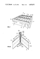
- FIG. 2 is a perspective view of a portion of the roof/reflector-concentrators and collectors of the embodiment of FIG. 1, illustrating the general layout.
- FIG. 2a is a fragmentary enlarged view of the central pivot arm zone of a modification of the invention.
- FIG. 3 is an enlarged fragmentary view, illustrating in more detail the collector support and movement-imparting arrangement.
- FIG. 3A is a further enlarged cross-sectional view of the collector.
- FIG. 4 illustrates a modified collector support arm connecting arrangement
- FIG. 5 illustrates a preferred arrangement for connecting adjoining reflector-concentrators.
- FIG. 6 is a schematic representation of a representative portion of the reflector-concentrators and collectors of the embodiment of FIGS. 1-3, with the ganged collectors being held horizontal during the parallelogram drive motion thereof, while FIG. 6A is a similar schematic representation illustrating the arcuate tilting motion of the ganged collectors in the modification of FIG. 4.
- FIGS. 7 and 8 are diagrammatic illustrations of the mode of operation of a single reflector-concentrator and collector of the arrangement of FIG. 1 at various times during the year, FIG. 8 also showing various angle and dimensional relationships for a given preferred embodiment of a single reflector-concentrator and collector.
- a heat utilization building structure such as a house, school, factory, etc., generally indicated at 11, has a roof/reflector-concentrator surface 21, formed by a plurality of individual reflector-concentrators 31 and may also have a further roof surface or surfaces of any desired configuration if so desired.
- the extent of roof/reflector-concentrator surface 21 is generally dependent upon the amount of solar energy needed for a given desired use. For maximum energy collection from a given roof size, the entire roof may be formed as a reflector-concentrator assembly 21, as generally illustrated in the illustrative embodiment. Windows 15 and doors 17 may be provided in walls 13, as desired.
- the roof/reflector-concentrator surface is formed by a plurality of laterally adjacent individual reflector-connectors 31 which form effective water-tight roof sections and which are connected together at their lateral edges in substantially laterally adjoining relation to effect a water-tight roof construction.
- the interconnected reflector-connectors may be suitably mounted and carried on the various upright and cross members forming the load-bearing building framework 101, as through the medium of complementary concave cradles generally indicated at 36, which may be suitably spaced at the ends of the individual reflectors 31, and otherwise located if desired or needed for a given size or load.
- Second and end covers 32, 32a may be suitably secured along the respective sides and ends of the roof/reflector-concentrator surface 21 in order to effectively seal the sides and ends of the roof against rain entry, and gutters 111 may be provided along the ends of each bank of reflector-concentrators 31, the illustrative embodiment having two banks of reflector-concentrators 31 forming the roof 21, with three gutters at the respective outboard opposite and adjacent opposing ends of the two banks of reflectors. Rain water will thus be drained along the troughs formed by the reflectors 31 and into the gutters, from which the rain water may be discharged to the ground as through suitable downspouts or down-guttering (not shown) as necessary or desired.
- a suitable facia generally indicated at 19 may be provided as an aesthetic enclosure and wind break around the reflector-concentrator roof 21, as desired, although there will be a small sacrifice in overall efficiency due to end shadowing from the facia on the reflectors 31 with the facia extending above the reflectors to any appreciable extent.
- Each reflector-concentrator 31 may be formed of any suitable solar reflective material, such as metal, glass, plastic, and such materials may be of load-bearing type and provide some, a major portion, or all of the roof surface construction strength or may be of nonload-bearing substrate.
- the desired curvature of each roof/reflector-concentrator 31 may be formed as a smooth curve or as straight or curved line segments.
- a curved metal roof surface may be formed in one continuous sweep, or in several panels, or various normally straight panels of metal, glass, plastic, etc. may be utilized in suitably joined relation to form the desired overall curved shaped roof/reflector-concentrator surface 31.
- the roof 21 may also be only partially reflective in parts thereof or in whole, if so desired, in order to provide for natural lighting of the interior of the building by light passage through the roof 21.
- the section 31 of the roof may also transmit light to the building interior if so desired.
- the roof/reflector-concentrators 31 face upwardly preferably with their opposite ends oriented directly East-West for maximum energy utilization, although other compass orientations may be utilized with less efficient operation.
- Each roof/reflector-concentrator 31 reflects and concentrates solar energy into a zone of maximum confluence which varies in position as a function of the angle of the sun with respect to the horizontal, as measured in a North-South vertical plane passing through the roof 21.
- a solar energy collector 51 is movably mounted, as by pivot arms 45, for back-and-forth movement in a North-South direction above each respective reflector-collector 31.
- the collector pivot support arms 45 are pivoted along a horizontal East-West line which may extend beneath, above or at the surface of the respective reflector-concentrator 31, with generally only small differences in effectiveness of the reflector/collector assembly 31, 51.
- the arms 45 are mounted on pivot support bearings 81c which lie beneath the surface of the roof reflector 21.
- the ratio of the reflector chord/length subtended area versus the effective collection area of the collectors 51 is approximately 15 to 1, thereby providing a maximum feasible concentration or amplification factor of no more than approximately 15 for an individual reflector/collector unit 31, 51 considered alone, although some spurious reflection from adjoining reflectors 31 may increase the pickup to some extent.
- the pivoted support arms 45 are preferably suitably ganged together as by linkage rods or beams 71 or the like to provide simultaneous ganged motion of the various collectors 51 relative to their respective reflector-concentrators 31.
- Ganged parallelogram movement of the pivoted support arms and horizontal linkage beams 71 may be suitably effected as by pivoted drive arms 81 connected through a torque tube 91 and pivotally mounted in pivot support bearings 81c on cross-members of the building framework 101, under one of the reflector-concentrators 31, as more particularly shown in FIG. 3.
- a support brace 83 may extend to aid in stabilizing the pivot pin 81a for drive arm 81.
- Pivoted back-and-forth motion of the drive arm 81 about its pivot 81a may be suitably effected by a drive motor M and screw jack 83, the screw jack being preferably of the circulating ball screw motion type, and this assembly M, 84 may be pivotally pinned and carried between a pivot pin 83a carried by the building framework and a pivot pin 83b at the lower short legend of the drive arm 81.
- the pivoted support arm 45 may be suitably pivotally mounted as indicated at 45a in respective bearings secured to the building framework 101, and the upper ends of the arms 45 may be pivotally secured to the horizontal linkage 71 through respective pivot pins 45b.
- the effective lengths and angles of arms 45 and 81 are the same, whereby effective parallelogram motion may be effected for this collector movement assembly.
- the collectors 51 are maintained horizontal in their various positions above the respective reflector-concentrators 31, through the securement of the ends of the collectors 51 to the horizontal linkage beams 71, as through the medium of bolts 73.
- This horizontal facing of the collectors 51 down toward their respective reflectors aids in energy retention by the collectors 51 by minimizing heat losses particularly from convection loss which is greater with a tilted altitude of the collector receiving face.
- the collectors 51 may be secured to the respective pivoted arms 345, as shown in FIGS. 4 and 6A, and parallelogram motion of the arms 345 and ganging linkage beam 371, pivotally interconnected as by pin 345b, will effect tilting movement of the collectors 51 as a function of pivoted movement of the arms 345.
- FIG. 3 A preferred reflector-concentrator construction is illustrated in FIG. 3, in which glass mirror segments 31a are cemented to a suitably curved sandwich formed of sheet metal 33, rigid insulating foam 35, and sheet metal 37.
- This construction enables the formation of a suitably rigid mirror reflector with a desired curvature, and which will withstand the necessary weather loads.
- the various layers of the curved sandwich 31a, 33, 35, 35 and 37 may be suitably bonded together as a unit through cement or the like, and multiple layers of foam 35 may be employed to enable ease of curve formation thereof particularly if such is not precast in the desired curvature.
- the glass mirror segments 31a may be omitted, with decrease in reflection efficiency being effected for most other effectively utilizable surfaces such as polished aluminum, steel, or other sheet metal or the like as the reflector surface which might thus be formed by the sheet 33 of the reflector 31 sandwich construction.
- Other constructions for reflector-concentrators may be utilized, as desired.
- the reflector-concentrators 31 are suitably interconnected at their adjoining edges to effect a water-tight joint.
- a connecting arrangement according to the invention is illustrated in FIG. 5, including male and female edge moldings 41, 43, which may be formed as metal (e.g. aluminum, magnesium, steel, etc.) extrusions extending along all or a major portion of the length of the adjoining reflector-concentrators 31.
- the male edge molding 43 has an upper male edge 43a which nests within a rubber sealing gasket 44b disposed within a reverse lip 41a of the female edge molding 41, and interfitting spacer ridges 41l, 43l run along the intermediate lower ends of the respective moldings.
- a further rubber sealing and mounting gasket 44a is compressed between the moldings 41, 43 within the space above ridges 41l, 43l, and the entire assembly 41, 43, 44a, 44b is secured together through multiple longitudinally spaced bolts 47 and nuts 47a.
- the longitudinal edges of adjoining reflector-concentrators 31 are retained between upper and lower angled flanges 41fu, 41fu and 43fu, 43 fu on the respective interfacing edge moldings 41 and 43.
- Each collector 51 may be suitably formed with a plurality of laterally side-by-side fluid flow heat transfer tubes 57a, 57b through which a suitable fluid, such as water, gas, etc. may be flowed for collection of the reflected solar energy from its respective reflector-concentrator 31.
- a suitable fluid such as water, gas, etc.
- These tubes 58a, 57b may be connected for in-flow at one and and out-flow at the other end of the collector 51, or preferably as shown, may be reverse-flow interconnected at one end of the collector for increased fluid flow path length within the concentrator as well as simplified external fluid interconnection thereto and therefrom.
- the parallel flow tubes 57a, 57b may be suitably connected, as through flexible home conduits 49a, 49b carried in a common protective insulating sheath or jacket 49 with common feed and return conduits 47a, 47b.
- Feed and return conduits 47a, 47b may be connected in parallel with in-flow and out-flow side-by-side conduits 57a, 57b of each of the collectors 51, and is heat exchange fluid, preferably liquid, such as water may be pumped through the conduits 47a, 47b, 49a, 49b, and 57a, 57b.
- the collectors 51 are formed with their respective reflected energy absorption elements 59, 57a, 57b facing downward toward the respective reflector-concentrator, and thereby enabling the interception of the solar reflection thereto from reflector 31 at a given proper angle of this assembly.
- Collectors 51 preferably are insulated at their outer surfaces facing away from reflector 31, as by rigid or other plastic foam or other suitable insulation 55, with a rigid opaque wrap-around generally U-shaped structural beam-like cover element 53, which may suitably be formed as a metal extrusion.
- a solar energy transparent cover glass plate or plates 58 may be secured beneath the energy absorption tubes 57a, 57b, with a downwardly finned black body heat-absorbing heat-sink block secured in spaced relation above the cover glass 58, as by anchoring in the plastic foam insulation with a longitudinal ridge anchor connector running along the length of the block 59.
- Elastic shock-resistant seals such as soft rubber gasket seals 56 may suitably retain the cover glass 58 within the beam cover element 53.
- the fluid conduit tubes 57a, 57b are carried in intimate direct contact with the finned black body heat-sink block 59, as by embedding in the heat-sink block 59 or laying the tubes 57a, 57b in longitudinal grooves in the upper side of the block 59 and crimping longitudinal lips adjoining the grooves down around the tubes 57a, 57b, as illustrated. Heat absorbed by the black body finned heat-sink block will be conducted directly to the intimately held fluid passage tubes 57a, 57b and the fluid passing therethrough.
- This construction together with the horizontal positioning of the collectors 51 in their various lateral positions aids in effecting a desired efficiency of energy collection and transfer at the collectors while also minimizing energy losses which may occur through convection with a tilted collector altitude.
- Fluid feed and return lines 47a, 47b may be suitably connected to a desired heat utilization system, such as a heat storage and building interior heating arrangement, and/or a cooling system, such as one based on absorption cooling principles.
- a desired heat utilization system such as a heat storage and building interior heating arrangement
- a cooling system such as one based on absorption cooling principles.
- various machinery may be caused to perform work by the solar heat transferred to the fluid in collectors 51, or other desired and suitable heat derived work may be performed.
- fluid temperatures such as for water as the fluid, may be raised to as high as 300° F. or more, dependent on fluid flow rate, relative sizes of collector and reflector, etc. Practical heating and absorption cooling may be accomplished well within and below this temperature extent for the fluid L flowed through the collector 51.
- the individual reflector concentrators 31 each have a semi-cylindrical concave reflecting surface which is formed of adjoining arcuate segments S1A, S2, and S1B, the opposite outermost arcuate segments being preferably identical in radius and arcuate length and being of lesser radius of curvature R1, R3 than the radius of curvature of the central arcuate segment S2.
- the concavely curved trough segments S1A and S1B curve up at a sharper rate than does the central segment S2, and thereby aid in maximizing overall confluence of the reflected solar rays into a zone for interception by the respective collector 51 at various sun angles encountered throughout the year.
- the adjoining reflector-concentrators 31 may be simply interconnected to form a roof of an overall flat, though obviously more detailedly undulating envelope configuration for use on building structures where such a roof is most desirable, including particularly institutional, industrial, and some residential buildings.
- the vertically facing symmetrical three-radii reflector-concentrator configuration is effective to provide a substantial degree of concentration of solar energy onto the collectors 51, the precise degree of concentration varying with the sun angle, and varying generally from approximately 6:1 to approximately 10 or 11:1 concentration ratio in the illustrative embodiment for a latitude of approximately 28° North latitude.
- FIG. 8 diagrammatically shows the effective reflected solar energy envelope zones intercepted by the collector in the illustrative embodiment for various periods of the year, namely at mid-day summer solstice, mid-day spring/fall equinox, and mid-day winter solstice.
- the zones of effective reflection on the mirror surface of reflector-concentrator 31 are indicated respectively at SESM, SEF/SM and SEWM on this diagram.
- a particular illustrative embodiment of the individual reflector-concentrators 31 and collectors 51 for a latitude of approximately 28°, such as generally illustrated, may suitably employ the following relationships, referring to FIG. 7 for reference characters and elements:
- this illustrative reflector may be utilized, if desired, with a simple change in the length of the pivot arm and the location of the pivot position 45a for movement of collector 51 as determined by a plot of the reflection angles of the sun from the various curved surfaces of the reflector-concentrator at the various sun angles encountered at the given latitude, and thereupon selecting the optimum arcuate motion path for the collector 51, which will thus dictate the arm 45 length and pivot 45a position.
- the length of arm 45 is shortened to 32 units, with length f being lengthened to 21 units and length g being zero, in order to obtain a desired extent of concentrated energy collection day by day throughout the year, in this latitude location.
- Determination of location of collectors 51 for each solar angle may be precisely determined for a given reflector 31, either by empirical plotting, or computer or other mathematical analysis of the confluence lines along the front-to-back extent of the reflector with the collector positioned for the particular desired maximizing of reflected solar energy interception at the various sun angles, with such compromises between maximums at various angles as may be desired for a given location and utilization.
- Positioning of the arms 45 and collectors 51 may be effected either on a predetermined control basis, or by energy sensing and feedback control of the drive means for movement of the collectors 51.
- each arm 45 and collector 51 might also be separately driven and controlled if so desired, though such will not normally be desirable.
- arc segments S1A, S2 and S1B are smoothly joined at a common point of tangency, a common tangency radius line extending through the centers of radius R1C and R2C as well as R2C and R3C for the three radii R1, R2 and R3.
- zones of reflected solar energy confluence for the illustrative embodiment are schematically shown in FIG. 8, the zones being only approximately shown and representing the midday times at approximately 28° N latitude for the sun's position at noon on each of the winter solstice, summer solstice and spring and fall equinoxes. It has been found that a good ratio of energy concentration and collection can be obtained over the major insolation periods of each day of the year by utilization of three or more radii for respectively three or more of the sections of the roof reflector 21, the radii being lesser in length for arc segments increasingly spaced from the lateral center of the respective reflector-concentrator 31.
- the reflector can and does accommodate solar angles to a limited degree behind the 90° vertical.
- the side or end angle of inclination must also be considered, and in order to maximize solar energy collection at low end angles the same as measured in the East-West vertical plane, the reflectors 31 and collectors 51 should desirably be relatively long along their length, particularly with respect to the distance of the collectors 51 from the reflectors 31.
- the daily excursions of movement required for the ganged arm/collector assemblies 45, 51 decrease, until at the respective two equinoxes the ganged arm/reflector assemblies 45, 51 require no angular movement as the sun rises and sets on the East-West orientation line of the reflector axes, and forms a constant angle throughout the day as measured in a North-South vertical plane passing through the reflectors 31.
- the solar concentration factors, or amplification factors vary with the solar angle.
- the concentration or amplification factor is a function of the extent of coverage or interception of the zone of confluence of the reflected solar energy at a given sun angle, and it is therefore desirable to maximize this extent of interception at the various angular positions of the sun and the collector/arm assemblies 51, 45, insofar as is practical and economical.
- the horizontal pivot line for pivot support arms 45 is disposed slightly beneath the effective reflective surface of respective reflectors 31, and is spaced from the center of longitudinal center line of the reflector 31 in a direction away from the Equator, the extent of desired displacement varying with the latitude of the user location.
- this arm pivot line may if desired be otherwise located for a given embodiment, as for instance above or at the surface of reflector 31.
- the common center pivot arms 45 for the longitudinally paired collectors 51 of the two banks of reflectors 31 are replaced by separate individual center zone individual pivot support arms 245, and the respective longitudinally paired collectors 51 of the two side-by-side banks of reflector/collector units are individually tied together only through the common drive torque tube 91 which serves to impart pivotal movement to the parallelogram linkage 45, 81, 71, 245, 271, 81, 245, 271, 81, etc. for each end of the ganged groups of collectors 51, 51 etc.
- the typical specific illustrative example proportions as previously shown and described, particularly with respect to FIG. 7, are, as previously noted, for an embodiment and practice of the invention primarily within a latitude of approximately 28°. Also, as noted, the embodiment is arranged such that the concentration factors for summer, spring and fall solar energy collection are maximized, to some extent at the expense of winter concentration factors, in order to maximize available solar-derived heat energy for air conditioning, (although still enabling the satisfaction of minimum requirements for heating during at least the major portion of most winter conditions).
- the reflectors 31 may be formed as a single or multiple reflector assemblies and other than as a roof of a building, although this is normally the most advantageous and preferred embodiment.
- a pivoted support arm arrangement 45 and particularly a ganged movement arrangement, is illustrated and preferred for supporting and moving the collectors 51 through the desired zone of movement, various other collector supporting and movement arrangements may be employed.
- radii R1, R2 and R3 are employed in the illustrative example, especially for simplicity of design and construction, more than three radii may be suitably employed, graduating from shortest at the front and rear to the longest at the center zone of the reflector-concentrator 31, and may in fact be constructed with a continuously varying radius from front to back of the reflector 31.
- Such a continuously varying radius reflector 31 may, however, be beyond the desired complexity for normal construction and the triple radius construction is considered to be adequate and most easily constructed from a practical standpoint. Accordingly, the invention is not to be limited to the particular illustrative embodiment and mode of operation and practice, but only by the scope of the appended claims.
Abstract
Description
______________________________________
Radii R1 and R3 of front and rear arc seg-
                         62     units
ments S1A and S1B
Radius R2 of center arc segment S2
                         81     units
Effective width CW of collector 51
                          6     units
Length of pivot arm 45   403/4  units
Length a                 24     units
Lengths b and c, each    21     units
Length d                 24     units
Length e                 151/3  units
Length f                 61/4   units
Length g                  4     units
Arc segments S1A and S1B 27     units
Arc segment S2           43     units
Minimum sun angle MNS desired to be accom-
                         17     degrees
modated by collector 51
Maximum sun angle MXS desired to be accom-
                         104    degrees
modated by collector 51
Minimum required angle MNC for collector/
                          7      degrees
arm assembly  51, 45 to accomodate
maximum desired sun angle (of approx-
imately 104 degrees)
Maximum required angle MXC for collector/
                         147     degrees
arm assembly  51, 45 to accommodate
minimum desired sun angle (of approx-
imately 18 degrees)
______________________________________
Claims (4)
Priority Applications (1)
| Application Number | Priority Date | Filing Date | Title |
|---|---|---|---|
| US06/659,211 US4602853A (en) | 1976-11-30 | 1984-10-09 | Solar energy concentrating and collecting arrangement |
Applications Claiming Priority (3)
| Application Number | Priority Date | Filing Date | Title |
|---|---|---|---|
| US74605076A | 1976-11-30 | 1976-11-30 | |
| US33840482A | 1982-01-08 | 1982-01-08 | |
| US06/659,211 US4602853A (en) | 1976-11-30 | 1984-10-09 | Solar energy concentrating and collecting arrangement |
Related Parent Applications (1)
| Application Number | Title | Priority Date | Filing Date |
|---|---|---|---|
| US33840482A Continuation | 1976-11-30 | 1982-01-08 |
Publications (1)
| Publication Number | Publication Date |
|---|---|
| US4602853A true US4602853A (en) | 1986-07-29 |
Family
ID=27407266
Family Applications (1)
| Application Number | Title | Priority Date | Filing Date |
|---|---|---|---|
| US06/659,211 Expired - Fee Related US4602853A (en) | 1976-11-30 | 1984-10-09 | Solar energy concentrating and collecting arrangement |
Country Status (1)
| Country | Link |
|---|---|
| US (1) | US4602853A (en) |
Cited By (20)
| Publication number | Priority date | Publication date | Assignee | Title |
|---|---|---|---|---|
| US5069540A (en) * | 1990-10-18 | 1991-12-03 | Gonder Warren W | Parabolic solar collector body and method |
| WO1996027771A1 (en) * | 1995-01-26 | 1996-09-12 | Myles John F Iii | An improved solar energy concentrating system having replaceable reflectors |
| AU699632B2 (en) * | 1995-01-26 | 1998-12-10 | Louis J Gerics | Solar energy concentrating system having replaceable reflectors |
| US5899199A (en) * | 1995-03-28 | 1999-05-04 | Mills; David | Solar energy collector system |
| WO1999023424A1 (en) * | 1997-11-04 | 1999-05-14 | Solel Consumer, Naamloze Vennootschap | Device for reflecting solar rays |
| US6131565A (en) * | 1996-12-20 | 2000-10-17 | Stanwell Corporation Limited | Solar energy collector system |
| US20050284074A1 (en) * | 2004-06-11 | 2005-12-29 | Dan Armstrong | Panel lock building system and hinge |
| US20080121226A1 (en) * | 2006-09-26 | 2008-05-29 | Neff Jacque A | Cementitious Solar Trough |
| WO2009083626A1 (en) * | 2007-12-28 | 2009-07-09 | Tecnologia Solar Concentradora, Sl | Solar energy concentrator/collector device |
| US20100170560A1 (en) * | 2008-06-19 | 2010-07-08 | Richard Sabino Sapienza | Durable, lightweight, and efficient solar concentrator |
| US20100325991A1 (en) * | 2009-05-22 | 2010-12-30 | Stephen John Trower | Building panel |
| US20110242689A1 (en) * | 2008-06-06 | 2011-10-06 | Keith Malcolm Lovegrove | Solar thermal collectors |
| EP2409092A1 (en) * | 2009-03-16 | 2012-01-25 | B. Shawn Buckley | Solar energy module |
| US20120103323A1 (en) * | 2009-07-15 | 2012-05-03 | Solarlite Gmbh | Segment of a solar collector and solar collectors |
| US20150244307A1 (en) * | 2012-11-08 | 2015-08-27 | D. Kevin CAMERON | Modular structural system for solar panel installation |
| US20160153683A1 (en) * | 2013-07-23 | 2016-06-02 | Paolo Chiaves | Structure of a concentrator mirror for concentrating solar energy |
| US10008977B2 (en) | 2013-09-10 | 2018-06-26 | Solarflame Corporation | Heliostat apparatus and solar heat collecting apparatus and concentrating photovoltaic apparatus |
| WO2019097081A1 (en) * | 2017-11-20 | 2019-05-23 | Nodin-Innovation As | A solar energy concentrating roof module and a solar energy conversion system for a roof |
| EP3828478A1 (en) * | 2019-11-28 | 2021-06-02 | Commissariat à l'énergie atomique et aux énergies alternatives | Solar reflector comprising mirrors with rays of different curvature |
| US11309829B2 (en) * | 2018-04-10 | 2022-04-19 | Barry Sgarrella | Dynamically shifting photovoltaic panel array apparatus |
Citations (5)
| Publication number | Priority date | Publication date | Assignee | Title |
|---|---|---|---|---|
| US3353317A (en) * | 1965-06-17 | 1967-11-21 | Ensor Arthur John | Panel joint with hook-shaped bolt connecting device |
| US3354595A (en) * | 1964-11-05 | 1967-11-28 | Abciuk & Co Ltd M | Acoustic panels and ceilings |
| US3608263A (en) * | 1969-11-13 | 1971-09-28 | Robertson Co H H | Hanger tabs for sheet metal decking sections |
| US3859000A (en) * | 1972-03-30 | 1975-01-07 | Reynolds Metals Co | Road construction and panel for making same |
| US4091796A (en) * | 1976-08-16 | 1978-05-30 | Owens-Illinois, Inc. | Solar energy collection apparatus |
-
1984
- 1984-10-09 US US06/659,211 patent/US4602853A/en not_active Expired - Fee Related
Patent Citations (5)
| Publication number | Priority date | Publication date | Assignee | Title |
|---|---|---|---|---|
| US3354595A (en) * | 1964-11-05 | 1967-11-28 | Abciuk & Co Ltd M | Acoustic panels and ceilings |
| US3353317A (en) * | 1965-06-17 | 1967-11-21 | Ensor Arthur John | Panel joint with hook-shaped bolt connecting device |
| US3608263A (en) * | 1969-11-13 | 1971-09-28 | Robertson Co H H | Hanger tabs for sheet metal decking sections |
| US3859000A (en) * | 1972-03-30 | 1975-01-07 | Reynolds Metals Co | Road construction and panel for making same |
| US4091796A (en) * | 1976-08-16 | 1978-05-30 | Owens-Illinois, Inc. | Solar energy collection apparatus |
Cited By (36)
| Publication number | Priority date | Publication date | Assignee | Title |
|---|---|---|---|---|
| US5069540A (en) * | 1990-10-18 | 1991-12-03 | Gonder Warren W | Parabolic solar collector body and method |
| WO1996027771A1 (en) * | 1995-01-26 | 1996-09-12 | Myles John F Iii | An improved solar energy concentrating system having replaceable reflectors |
| EP0805940A1 (en) * | 1995-01-26 | 1997-11-12 | Myles, John F. III | An improved solar energy concentrating system having replaceable reflectors |
| AU699632B2 (en) * | 1995-01-26 | 1998-12-10 | Louis J Gerics | Solar energy concentrating system having replaceable reflectors |
| EP0805940A4 (en) * | 1995-01-26 | 1999-04-21 | John F Myles Iii | An improved solar energy concentrating system having replaceable reflectors |
| US5899199A (en) * | 1995-03-28 | 1999-05-04 | Mills; David | Solar energy collector system |
| US6131565A (en) * | 1996-12-20 | 2000-10-17 | Stanwell Corporation Limited | Solar energy collector system |
| BE1011529A3 (en) * | 1997-11-04 | 1999-10-05 | Solel Consumer Naamloze Vennoo | Device for reflect of solar radiation. |
| WO1999023424A1 (en) * | 1997-11-04 | 1999-05-14 | Solel Consumer, Naamloze Vennootschap | Device for reflecting solar rays |
| US20050284074A1 (en) * | 2004-06-11 | 2005-12-29 | Dan Armstrong | Panel lock building system and hinge |
| US7513081B2 (en) * | 2004-06-11 | 2009-04-07 | Dan Armstrong | Panel lock building system and hinge |
| US20080121226A1 (en) * | 2006-09-26 | 2008-05-29 | Neff Jacque A | Cementitious Solar Trough |
| US8764207B2 (en) * | 2006-09-26 | 2014-07-01 | Jacque A. Neff | Cementitious solar trough |
| WO2009083626A1 (en) * | 2007-12-28 | 2009-07-09 | Tecnologia Solar Concentradora, Sl | Solar energy concentrator/collector device |
| ES2326353A1 (en) * | 2007-12-28 | 2009-10-07 | Tecnologia Solar Concentradora, S.L. | Solar energy concentrator/collector device |
| ES2326353B1 (en) * | 2007-12-28 | 2010-07-13 | Tecnologia Solar Concentradora, S.L. | SOLAR ENERGY CONCENTRATOR-CAPTURE DEVICE. |
| CN102239369A (en) * | 2007-12-28 | 2011-11-09 | 太阳能技术中心公司 | Solar energy concentrator/collector device |
| US20110168160A1 (en) * | 2007-12-28 | 2011-07-14 | Tecnologia Solar Concentradora, Sl | Solar energy concentrator-collector device |
| US20110242689A1 (en) * | 2008-06-06 | 2011-10-06 | Keith Malcolm Lovegrove | Solar thermal collectors |
| US9057536B2 (en) * | 2008-06-06 | 2015-06-16 | Sunrise Csp Pty Limited | Solar thermal collectors |
| US20100170560A1 (en) * | 2008-06-19 | 2010-07-08 | Richard Sabino Sapienza | Durable, lightweight, and efficient solar concentrator |
| US8878049B2 (en) * | 2008-06-19 | 2014-11-04 | Persistent Energy, Llp | Durable, lightweight, and efficient solar concentrator |
| EP2409092A1 (en) * | 2009-03-16 | 2012-01-25 | B. Shawn Buckley | Solar energy module |
| EP2409092A4 (en) * | 2009-03-16 | 2014-05-07 | B Shawn Buckley | Solar energy module |
| US8833027B2 (en) * | 2009-05-22 | 2014-09-16 | Stephen John Trower | Building panel |
| US20100325991A1 (en) * | 2009-05-22 | 2010-12-30 | Stephen John Trower | Building panel |
| US20150267940A1 (en) * | 2009-07-15 | 2015-09-24 | Johannes Furst Zu Waldburg -Wolfegg Und Waldsee | Segment of a Solar Collector and Solar Collectors |
| US20120103323A1 (en) * | 2009-07-15 | 2012-05-03 | Solarlite Gmbh | Segment of a solar collector and solar collectors |
| US20150244307A1 (en) * | 2012-11-08 | 2015-08-27 | D. Kevin CAMERON | Modular structural system for solar panel installation |
| US20160153683A1 (en) * | 2013-07-23 | 2016-06-02 | Paolo Chiaves | Structure of a concentrator mirror for concentrating solar energy |
| US10006667B2 (en) * | 2013-07-23 | 2018-06-26 | Paolo Chiaves | Structure of a concentrator mirror for concentrating solar energy |
| US10008977B2 (en) | 2013-09-10 | 2018-06-26 | Solarflame Corporation | Heliostat apparatus and solar heat collecting apparatus and concentrating photovoltaic apparatus |
| WO2019097081A1 (en) * | 2017-11-20 | 2019-05-23 | Nodin-Innovation As | A solar energy concentrating roof module and a solar energy conversion system for a roof |
| US11309829B2 (en) * | 2018-04-10 | 2022-04-19 | Barry Sgarrella | Dynamically shifting photovoltaic panel array apparatus |
| EP3828478A1 (en) * | 2019-11-28 | 2021-06-02 | Commissariat à l'énergie atomique et aux énergies alternatives | Solar reflector comprising mirrors with rays of different curvature |
| FR3103889A1 (en) * | 2019-11-28 | 2021-06-04 | Commissariat A L'energie Atomique Et Aux Energies Alternatives | Solar reflector with mirrors with different radii of curvature |
Similar Documents
| Publication | Publication Date | Title |
|---|---|---|
| US4602613A (en) | Solar energy concentrating and collecting arrangement | |
| US4602853A (en) | Solar energy concentrating and collecting arrangement | |
| US3994435A (en) | Solar energy concentrating and collecting arrangement and method | |
| US4004574A (en) | Solar energy concentrating and collecting arrangement with sun-follower and solar energy sensing power control and method | |
| US6349718B1 (en) | Device for heating with solar energy | |
| US4771764A (en) | Water-borne azimuth-altitude tracking solar concentrators | |
| US4148301A (en) | Water-borne rotating solar collecting and storage systems | |
| US3991741A (en) | Roof-lens solar collector | |
| US4120282A (en) | Solar radiation reflector and collector array | |
| US4296731A (en) | Tracking booster and multiple mirror concentrator floating collector | |
| US4020827A (en) | Solar energy collecting system | |
| KR100375113B1 (en) | A roof having an integral solar energy concentrating system | |
| US4203426A (en) | Solar energy converter carousel mounted rack | |
| US4122833A (en) | Non-tracking solar energy collector system | |
| US4832002A (en) | Unified heliostat array | |
| US4597377A (en) | Solar reflector system | |
| US4084578A (en) | Solar water heater of natural circulation type | |
| US20080257335A1 (en) | Enclosed solar collector | |
| US4307710A (en) | Solar energy collector system | |
| US4566434A (en) | Solar energy collector | |
| CA1130671A (en) | Solar energy collector/reflector arrangement | |
| US4210128A (en) | Black liquid absorbing solar collector | |
| US4462392A (en) | Fixed solar collection system | |
| WO2009006355A9 (en) | Solar power harvester with reflective border | |
| US4538886A (en) | Circular arc solar concentrator |
Legal Events
| Date | Code | Title | Description |
|---|---|---|---|
| REMI | Maintenance fee reminder mailed | ||
| FPAY | Fee payment |
Year of fee payment: 4 |
|
| SULP | Surcharge for late payment | ||
| FEPP | Fee payment procedure |
Free format text: PAYOR NUMBER ASSIGNED (ORIGINAL EVENT CODE: ASPN); ENTITY STATUS OF PATENT OWNER: LARGE ENTITY |
|
| REMI | Maintenance fee reminder mailed | ||
| LAPS | Lapse for failure to pay maintenance fees | ||
| FP | Lapsed due to failure to pay maintenance fee |
Effective date: 19940803 |
|
| AS | Assignment |
Owner name: FIRST UNION COMMERCIAL CORPORATION, VIRGINIA Free format text: ASSIGNMENT OF ASSIGNORS INTEREST;ASSIGNOR:AAI CORPORATION;REEL/FRAME:008579/0748 Effective date: 19970611 |
|
| AS | Assignment |
Owner name: FLEET CAPITAL CORPORATION, NEW YORK Free format text: SECURITY INTEREST;ASSIGNOR:AAI CORPORATION;REEL/FRAME:011967/0619 Effective date: 20010628 |
|
| AS | Assignment |
Owner name: AAI CORPORATION, MARYLAND Free format text: RELEASE OF SECURITY INTEREST AND RECONVEYANCE;ASSIGNOR:FIRST UNION COMMERCIAL CORPORATION;REEL/FRAME:012153/0140 Effective date: 20010628 |
|
| AS | Assignment |
Owner name: AAI CORPORATION, MARYLAND Free format text: RELEASE OF SECURITY INTEREST;ASSIGNOR:FLEET CAPITAL CORPORATION;REEL/FRAME:016256/0111 Effective date: 20041227 |
|
| STCH | Information on status: patent discontinuation |
Free format text: PATENT EXPIRED DUE TO NONPAYMENT OF MAINTENANCE FEES UNDER 37 CFR 1.362 |