US4628370A - Apparatus for copying magnetic tape - Google Patents
Apparatus for copying magnetic tape Download PDFInfo
- Publication number
- US4628370A US4628370A US06/621,488 US62148884A US4628370A US 4628370 A US4628370 A US 4628370A US 62148884 A US62148884 A US 62148884A US 4628370 A US4628370 A US 4628370A
- Authority
- US
- United States
- Prior art keywords
- copying
- deck
- master
- mode
- tape
- Prior art date
- Legal status (The legal status is an assumption and is not a legal conclusion. Google has not performed a legal analysis and makes no representation as to the accuracy of the status listed.)
- Expired - Fee Related
Links
Images


Classifications
-
- G—PHYSICS
- G11—INFORMATION STORAGE
- G11B—INFORMATION STORAGE BASED ON RELATIVE MOVEMENT BETWEEN RECORD CARRIER AND TRANSDUCER
- G11B15/00—Driving, starting or stopping record carriers of filamentary or web form; Driving both such record carriers and heads; Guiding such record carriers or containers therefor; Control thereof; Control of operating function
-
- G—PHYSICS
- G11—INFORMATION STORAGE
- G11B—INFORMATION STORAGE BASED ON RELATIVE MOVEMENT BETWEEN RECORD CARRIER AND TRANSDUCER
- G11B5/00—Recording by magnetisation or demagnetisation of a record carrier; Reproducing by magnetic means; Record carriers therefor
- G11B5/86—Re-recording, i.e. transcribing information from one magnetisable record carrier on to one or more similar or dissimilar record carriers
Definitions
- the present invention relates to an apparatus for copying magnetic tape to simultaneously copy the contents of a master tape onto a plurality of blank tapes.
- the conventional apparatus for copying magnetic tape comprises, as shown in FIG. 1, an open reel type of master deck 2 having a master tape 1, and a cassette-type of a slave deck 4 connected to the master deck 2 for receiving a plurality of blank tapes 3 to be copied with the contents of the master tape 1.
- the contents of the master tape 1, on which the contents are recorded at 1.9 cm/sec., are reproduced via the master deck 2 at 3.8 cm/sec. and are recorded on the respective blank tapes 3 at the slave deck 4 side at 3.8 cm/sec., thereby copying the contents at twice the ordinary speed.
- the conventional apparatus for copying magnetic tape as described above is defective in that the taping operations should all be individually performed in the respective decks, such that the taping operations at the master deck 2 are all achieved at the master deck 2 side and the taping operations at the slave deck 4 are all achieved at the slave deck 4 side. Since the master deck 2 is ordinarily installed separately from the slave deck 4, operators must frequently reciprocate between the decks 2 and 4, with the result that the taping operations are not only performed with numerous tasks, but the efficiency of the copying operation is remarkably deteriorated.
- An object of the present invention is to provide an apparatus for copying magnetic tape which can eliminate the above-described drawbacks and permits a concentration of all operations including the taping operations in the master and slave decks and exchanging of blank tapes to be copied by the slave deck side and also permits the simplification of the operations and improvements in the efficiency of the duplicating process.
- Another object of the present invention is to provide an apparatus for copying magnetic tape which permits a concentration of all operations including taping operations in the master and slave decks and exchanging of blank tapes to be copied at the slave deck and also permits continuous and repetitive copying operations, simplification of the operations and improvements in the efficiency of the copying process.
- an apparatus for copying magnetic tape comprising: a slave deck having an operation panel and a plurality of copying units adapted to receive tapes to be copied; a master deck having a master tape and capable of providing a reproduced output from the master tape to the tape to be copied by the slave deck and producing start and finish signals corresponding respectively to the start and finish of the contents on the master tape to be copied; and control means responsive to operation of the operation panel for permitting the setting the copying units of the slave deck to a copying mode, rewinding mode or stopping mode, for setting the master deck to a reproducing mode, rewinding mode or stopping mode, and for causing rewinding of the tape to be copied and the master tape to initial state responsive to finish signals corresponding to the finish of the master tape's contents when the slave deck is set to the copying mode and the master deck is set to the reproducing mode.
- FIG. 1 is a schematic view showing the structure of an example of a conventional apparatus for copying magnetic tape
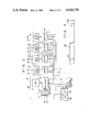
- FIG. 2 is a schematic view showing the structure of an embodiment of the present invention.
- FIG. 3 is a schematic view showing the structure of a copying unit used for the FIG. 3 embodiment.
- FIG. 4 is a schematic view showing the structure of a master tape used in the embodiment of the invention.
- reference numeral 10 designates a slave deck.
- reference numeral 11 designates an operation panel comprising, for example, a keyboard, which has a REWIND key 111, a COPY key 112, and a STOP key 113, and which also has displays for indicating displays corresponding to the operations of these keys 111 to 113 such as, for example, display lamps 111a to 113a.
- a central processing unit (which will be abbreviated as "CPU") 13 is connected through an interface 12 to the keyboard 11.
- the CPU 13 contains all control programs.
- reference numeral 14 depicts a plurality of (four, #1 to #4, in the embodiment shown) copying units which blank tapes to be copied (not shown) are set, and each copying unit 14 has a deck body 141, to which the blank tape to be copied is set, and a unit driver 142.
- An address bus 15, a data bus 16, and a remote line 17 are connected as unit buses between the unit driver 142 and the interface 12.
- the above-described unit driver 142 is concretely constructed as shown in FIG. 3, which shows only one unit driver 142. More specifically, the address bus 15 has four lines 151, 152, 153 and 154, two lines 151, 152 of which are connected to a selector 18, and the remaining two lines 153, 154 of which are connected to an address comparator 19. This comparator 19 generates a comparison output with a set address 191 to apply the comparison output to an enable terminal E of the selector 18 upon reception of a remote signal to the remote line 17. A strobe terminal S of latches 201 to 204 is connected to the output terminal of the selector 18.
- latches 201 to 204 are connected to four data lines 161 to 164 of the data bus 16 to output the data of the data bus 16 when a strobe pulse is applied to the strobe terminal S.
- reel motor driving relays 211 and 212 are connected to the latch 201 to apply a reel motor driving output to the deck body 141 through the contacts 211a and 212a of these relays 211 and 212.
- a drive circuit 22 of a solenoid for changing the mode is connected to the latch 202 to apply the solenoid driving output to the deck body 141 by the drive circuit 22.
- signals representing the tape running state from the deck body 141 such as, for example, tape constant speed running, high speed running, and stopping states are applied to the latch 203.
- These signals are obtained, for example, by providing a photoreflector, i.e., a reflecting plate at a rotating reel side, emitting a light to the reflecting plate and generating the respective state signals from the lights reflected on the reflecting plate. Further, a display circuit 23 for displaying the states is connected to the latch 204.
- a photoreflector i.e., a reflecting plate at a rotating reel side
- the master deck 26, in which the master tape 25 is received is connected through a control line 24 to the interface 12.
- the control line 24 has a line for instructing the PLAY of the master deck 26, a line for instructing the STOP, a line for instructing the REWIND, and a line for instructing the FASTFWD.
- a line 27 for feeding a sensing point signal is connected between the master deck 26 and the interface signal 12.
- the master tape 25 received in the master deck 26 employs, as shown in FIG. 4, conductive parts 251 and 252 such as aluminum foils respectively attached to the start and finish of the master tape's content to be copied.
- the master deck 26 detects the conductive part 251 to generate a sensing point signal of a copy start and detects the conductive part 252 to generate a sensing point signal of a copy end.
- the output of the master deck 26, i.e., the reproduced output of the master tape 25, is applied through the line 28 directly to the deck body 141 of the copying units 14 of #1 to #4 at the slave deck 10 side to be copied onto the blank tapes (not shown) set in the deck body 141.
- the address code is output to the address bus 15 and the data code is output to the data bus 16 in accordance with the program in the CPU 13.
- the address code is applied through the lines 151 and 152 of the address bus 15 to the selector 18, and the address code is also applied through the other lines 153 and 154 to the address comparator 19.
- the above-described operations are also sequentially performed in the copying units of #2 to #4 in the same manner as described above, and all the units 14 are set to the COPY mode.
- the settings of the COPY mode to the units 14 are sequentially executed by displacing, for a predetermined period of time, and considering the current capacity required for starting the motors and operating the solenoids of the respective units 14, thereby minimizing the current capacity as seen from the power source side.
- the PLAY signal is applied to the master deck 26 through the control line 24 by the operation of the COPY key 112 in the keyboard 11.
- the master deck 26 is set to the PLAY mode.
- the output of the master deck 26, i.e., the reproduced output of the master tape 25 is applied through the deck body 141 of the respective copying units 14 and copied on the blank tapes received in the deck body 141.
- the tape ends of the copy units 14 of #1 to #4 are checked by the program of the CPU 13 in this state.
- the latch 203 is selected for each copying unit 14 by the address code to the address bus 15 in this case, and the state signal of the photoreflector of the deck body 141 is detected through the data bus 15, thereby performing the check. In this manner, any of the blank tapes to be copied by the copying units 14 which has reached the end of copying due to a certain reason in the course the copying step is detected.
- the sensing point signal of the COPY end is generated based on the conductive part 252 shown in FIG. 4 and fed through the line 27 and the interface 14 to the slave deck 10 side.
- the copying unit 14 and the master deck 26 are temporarily set to the STOP mode by the program of the CPU 13, and when the STOPs of the units 14 and the master deck 26 are thereafter confirmed, the copying units 14 and the master deck 26 are set to the REWIND mode.
- the blank tapes thus copied are respectively rewound in the deck bodies 141 of the respective copying units 14 in this state, and the tape ends of the blank tapes thus copied are checked simultaneously.
- the address to the address bus 15 is selected for the latch 203 for each copying unit 14 by the address code to the address bus 15 in the same manner as described above, and the state signal of the photoreflector of the deck body 141 is detected through the data bus 16, thereby performing the check.
- the copying unit 14 which has the tape end is sequentially set to the STOP mode.
- the sensing point signal is generated based on the conductive part 251 shown in FIG. 4 and fed through the line 27 and the interface 12 to the slave deck 10 side.
- the master deck 26 is set to the STOP mode by the CPU 13. In this case, the master deck 26 is controlled until the tape is stopped accurately at the conductive part 251 of the master tape 25 and hence the start of the contents of the master tape 25. In this manner, the first copying operation of the blank tape to be copied has been completed.
- the respective copying units 14 can be set to the STOP mode by the address code of the address bus 15 and the data code of the data bus 16, and the copying operation can be interrupted.
- the copying units 14 are set to the REWIND mode by the address code of the address bus 15 and the data code of the data bus 16, and the blank tapes to be copied can be rewound.
- the taping operations of the master and slave decks can be performed by the keyboard operation at the slave deck side.
- all the operations including the exchange of the blank tapes to be copied by the slave deck side can be concentrated at the slave deck side, thereby remarkably simplifying the respective operations as compared with the conventional apparatus which requires frequent reciprocation between the decks by the operators, thereby significantly improving the efficiency of the copying operations.
- the present invention is not limited to the particular embodiment described above. Various other changes and modifications may be made within the spirit and scope of the present invention.
- the copying units 14 are immediately set to the COPY mode by the operation of the COPY key 112 in the keyboard 11.
- the respective COPY modes 14 can be temporarily set to the REWIND mode by the COPY key 112, the rewind of the blank tape to be copied is confirmed, and then the COPY mode may be set.
- the copying units 14 of #1 to #4 may again be set to the COPY mode in the same sequence as described above by the program of the CPU 13 upon stopping the tape, and the master deck 26 may be set to the PLAY mode.
- the blank tapes to be copied on the respective copying unit 14 may be exchanged with new ones because there is a predetermined period of time from when the above-described copying units 14 are sequentially stopped to when the master deck 26 is stopped accurately at the start of the contents of the master tape.
- the contents of the master tape 25 may be repeatedly copied on the blank tapes at the copying units 14 merely by exchanging the blank tapes thus copied with new crude tapes whenever the blank tapes are thus completely copied, and the blank tapes can be continuously copied in the same manner as described above.
- the tape operations of the master and slave decks can be concentrated to the slave deck side by the keyboard operation at the slave deck side with the operation including the exchange of the blank tapes to be copied at the slave deck side, and the copying operations can be continuously performed. Consequently, the respective operations can be remarkably simplified as compared with the conventional apparatus in which the operators should frequently move between the decks. Since the blank tapes thus copied are merely exchanged with new blank tapes after the copying operations are continuously achieved, the efficiency of the copying work can be significantly improved.
- the apparatus of the invention is constructed such that the copying unit is set to the STOP mode and a defect is indicated on the display circuit when any of the copying units becomes defective, the other copying units are operated to carry out the tape rewinding operations and when completed, the continuous operation is temporarily interrupted, the defective copying unit can be reliably notified, the optimum remedy can be performed for the defective copying unit, and the influence of the defect to the other copying units can be prevented in advance.
Abstract
An apparatus for copying magnetic tape, comprising a slave deck having an operation panel and a plurality of copying units for receiving tapes to be copied, a master deck having a master tape and capable of providing a reproduced output from the master tape to the tape to be copied by the slave deck and producing start and finish signals corresponding respectively to the start and finish of the master tape's contents to be copied, and a control unit responsive to operation of the operation panel for setting the copying units of the slave deck to a copying mode, rewinding mode, or stopping mode, for setting the master deck to a reproducing mode, rewinding mode, or stopping mode, and for causing rewinding of the tape to be copied and the master tape to their initial state responsive to finish signals corresponding to the finish of the master tape's contents when the slave deck is set to the copying mode and the master deck is set to the reproducing mode.
Description
The present invention relates to an apparatus for copying magnetic tape to simultaneously copy the contents of a master tape onto a plurality of blank tapes.
Recently, microcomputers have become increasingly popular, and various types of programs used therefor have been recorded on magnetic tapes and the tapes have been sold.
The contents of such magnetic tapes are copied from a master tape, and an apparatus for simultaneously copying onto a plurality of blank tapes is generally used.
The conventional apparatus for copying magnetic tape comprises, as shown in FIG. 1, an open reel type of master deck 2 having a master tape 1, and a cassette-type of a slave deck 4 connected to the master deck 2 for receiving a plurality of blank tapes 3 to be copied with the contents of the master tape 1. The contents of the master tape 1, on which the contents are recorded at 1.9 cm/sec., are reproduced via the master deck 2 at 3.8 cm/sec. and are recorded on the respective blank tapes 3 at the slave deck 4 side at 3.8 cm/sec., thereby copying the contents at twice the ordinary speed.
The conventional apparatus for copying magnetic tape as described above is defective in that the taping operations should all be individually performed in the respective decks, such that the taping operations at the master deck 2 are all achieved at the master deck 2 side and the taping operations at the slave deck 4 are all achieved at the slave deck 4 side. Since the master deck 2 is ordinarily installed separately from the slave deck 4, operators must frequently reciprocate between the decks 2 and 4, with the result that the taping operations are not only performed with numerous tasks, but the efficiency of the copying operation is remarkably deteriorated.
An object of the present invention is to provide an apparatus for copying magnetic tape which can eliminate the above-described drawbacks and permits a concentration of all operations including the taping operations in the master and slave decks and exchanging of blank tapes to be copied by the slave deck side and also permits the the simplification of the operations and improvements in the efficiency of the duplicating process.
Another object of the present invention is to provide an apparatus for copying magnetic tape which permits a concentration of all operations including taping operations in the master and slave decks and exchanging of blank tapes to be copied at the slave deck and also permits continuous and repetitive copying operations, simplification of the operations and improvements in the efficiency of the copying process.
According to one aspect of the present invention, there is provided an apparatus for copying magnetic tape, comprising: a slave deck having an operation panel and a plurality of copying units adapted to receive tapes to be copied; a master deck having a master tape and capable of providing a reproduced output from the master tape to the tape to be copied by the slave deck and producing start and finish signals corresponding respectively to the start and finish of the contents on the master tape to be copied; and control means responsive to operation of the operation panel for permitting the setting the copying units of the slave deck to a copying mode, rewinding mode or stopping mode, for setting the master deck to a reproducing mode, rewinding mode or stopping mode, and for causing rewinding of the tape to be copied and the master tape to initial state responsive to finish signals corresponding to the finish of the master tape's contents when the slave deck is set to the copying mode and the master deck is set to the reproducing mode.
According to the above-described construction of the apparatus for copying magnetic tape, since all the operations, including the tape operations in the master and slave decks and the exchanging of the blank tapes to be copied can be carried out at the slave deck side, the operations can be simplified, and the efficiency of the copying process can be improved.
FIG. 1 is a schematic view showing the structure of an example of a conventional apparatus for copying magnetic tape;
FIG. 2 is a schematic view showing the structure of an embodiment of the present invention;
FIG. 3 is a schematic view showing the structure of a copying unit used for the FIG. 3 embodiment; and
FIG. 4 is a schematic view showing the structure of a master tape used in the embodiment of the invention.
An embodiment of the present invention will be described with reference to the accompanying drawings.
In FIG. 2, reference numeral 10 designates a slave deck. In the slave deck 10, reference numeral 11 designates an operation panel comprising, for example, a keyboard, which has a REWIND key 111, a COPY key 112, and a STOP key 113, and which also has displays for indicating displays corresponding to the operations of these keys 111 to 113 such as, for example, display lamps 111a to 113a. A central processing unit (which will be abbreviated as "CPU") 13 is connected through an interface 12 to the keyboard 11. The CPU 13 contains all control programs.
On the other hand, reference numeral 14 depicts a plurality of (four, #1 to #4, in the embodiment shown) copying units which blank tapes to be copied (not shown) are set, and each copying unit 14 has a deck body 141, to which the blank tape to be copied is set, and a unit driver 142. An address bus 15, a data bus 16, and a remote line 17 are connected as unit buses between the unit driver 142 and the interface 12.
The above-described unit driver 142 is concretely constructed as shown in FIG. 3, which shows only one unit driver 142. More specifically, the address bus 15 has four lines 151, 152, 153 and 154, two lines 151, 152 of which are connected to a selector 18, and the remaining two lines 153, 154 of which are connected to an address comparator 19. This comparator 19 generates a comparison output with a set address 191 to apply the comparison output to an enable terminal E of the selector 18 upon reception of a remote signal to the remote line 17. A strobe terminal S of latches 201 to 204 is connected to the output terminal of the selector 18. These latches 201 to 204 are connected to four data lines 161 to 164 of the data bus 16 to output the data of the data bus 16 when a strobe pulse is applied to the strobe terminal S. In this case, reel motor driving relays 211 and 212 are connected to the latch 201 to apply a reel motor driving output to the deck body 141 through the contacts 211a and 212a of these relays 211 and 212. A drive circuit 22 of a solenoid for changing the mode is connected to the latch 202 to apply the solenoid driving output to the deck body 141 by the drive circuit 22. Further, signals representing the tape running state from the deck body 141 such as, for example, tape constant speed running, high speed running, and stopping states are applied to the latch 203. These signals are obtained, for example, by providing a photoreflector, i.e., a reflecting plate at a rotating reel side, emitting a light to the reflecting plate and generating the respective state signals from the lights reflected on the reflecting plate. Further, a display circuit 23 for displaying the states is connected to the latch 204.
Turning to FIG. 2, the master deck 26, in which the master tape 25 is received, is connected through a control line 24 to the interface 12. The control line 24 has a line for instructing the PLAY of the master deck 26, a line for instructing the STOP, a line for instructing the REWIND, and a line for instructing the FASTFWD. A line 27 for feeding a sensing point signal is connected between the master deck 26 and the interface signal 12. The master tape 25 received in the master deck 26 employs, as shown in FIG. 4, conductive parts 251 and 252 such as aluminum foils respectively attached to the start and finish of the master tape's content to be copied. The master deck 26 detects the conductive part 251 to generate a sensing point signal of a copy start and detects the conductive part 252 to generate a sensing point signal of a copy end.
The output of the master deck 26, i.e., the reproduced output of the master tape 25, is applied through the line 28 directly to the deck body 141 of the copying units 14 of #1 to #4 at the slave deck 10 side to be copied onto the blank tapes (not shown) set in the deck body 141.
The operation of the copying unit will now be described.
When a power source is energized, all the copying units 14 of #1 to #4 are checked as to whether or not they are in the STOP mode by the program in the CPU 13. In this case, the latch 203 of each unit 14 is selected by the address code to the address bus 15, and the state signal of the photoreflector of the deck body 141 is detected through the data bus 16 to execute the check.
Assume that all the units 14 are set to the STOP mode and the COPY key 112 is operated at the keyboard 11 in this state. After the fact that the key input, at this time effective to the mode (STOP mode at this time) of the respective units 14, is confirmed, the address code is output to the address bus 15 and the data code is output to the data bus 16 in accordance with the program in the CPU 13. By considering the copying unit 14 of #1 in this case, the address code is applied through the lines 151 and 152 of the address bus 15 to the selector 18, and the address code is also applied through the other lines 153 and 154 to the address comparator 19. When the address code coincides with the contents of the set address 191 at this time, a comparison output is applied to the enable terminal E of the selector 18 upon reception of the remote signal to the remote line 17. Therefore, when the latch 201 is selected by the selector 18, the data of the data bus 16 is loaded through the latch 201 and latched, the reel motor driving relays 211 and 212 are energized, and the reel motor driving output is applied to the deck body 141 side through the contacts 211a and 212a. Then, when the latch 202 is selected in the same manner as described above, the mode changing solenoid drive circuit 22 is energized, and the solenoid driving output is applied to the deck body 141 side. In this manner, the copying unit of #1 is set to the COPY mode.
The above-described operations are also sequentially performed in the copying units of #2 to #4 in the same manner as described above, and all the units 14 are set to the COPY mode. In this case, the settings of the COPY mode to the units 14 are sequentially executed by displacing, for a predetermined period of time, and considering the current capacity required for starting the motors and operating the solenoids of the respective units 14, thereby minimizing the current capacity as seen from the power source side.
On the other hand, the PLAY signal is applied to the master deck 26 through the control line 24 by the operation of the COPY key 112 in the keyboard 11. Thus, the master deck 26 is set to the PLAY mode. Then, the output of the master deck 26, i.e., the reproduced output of the master tape 25 is applied through the deck body 141 of the respective copying units 14 and copied on the blank tapes received in the deck body 141.
The tape ends of the copy units 14 of #1 to #4 are checked by the program of the CPU 13 in this state. The latch 203 is selected for each copying unit 14 by the address code to the address bus 15 in this case, and the state signal of the photoreflector of the deck body 141 is detected through the data bus 15, thereby performing the check. In this manner, any of the blank tapes to be copied by the copying units 14 which has reached the end of copying due to a certain reason in the course the copying step is detected.
Subsequently, when the master tape 25 is being reproduced in the master deck 26 and the contents of the tape 25 reaches the finish, the sensing point signal of the COPY end is generated based on the conductive part 252 shown in FIG. 4 and fed through the line 27 and the interface 14 to the slave deck 10 side. Then, the copying unit 14 and the master deck 26 are temporarily set to the STOP mode by the program of the CPU 13, and when the STOPs of the units 14 and the master deck 26 are thereafter confirmed, the copying units 14 and the master deck 26 are set to the REWIND mode.
The blank tapes thus copied are respectively rewound in the deck bodies 141 of the respective copying units 14 in this state, and the tape ends of the blank tapes thus copied are checked simultaneously. In this case, the address to the address bus 15 is selected for the latch 203 for each copying unit 14 by the address code to the address bus 15 in the same manner as described above, and the state signal of the photoreflector of the deck body 141 is detected through the data bus 16, thereby performing the check. When the tape end is detected, the copying unit 14 which has the tape end is sequentially set to the STOP mode. On the other hand, when the master tape 25 of the master deck 26 has arrived at the starting part of the contents of the master tape by the rewinding operation of the tape, the sensing point signal is generated based on the conductive part 251 shown in FIG. 4 and fed through the line 27 and the interface 12 to the slave deck 10 side. Thus, the master deck 26 is set to the STOP mode by the CPU 13. In this case, the master deck 26 is controlled until the tape is stopped accurately at the conductive part 251 of the master tape 25 and hence the start of the contents of the master tape 25. In this manner, the first copying operation of the blank tape to be copied has been completed.
Then, the blank tapes thus copied of the respective copying units 14 are replaced with new blank tapes, and the COPY key 112 is again operated in the keyboard 11. Then, the contents of the master tape 25 are copied on the blank tapes on the respective copying units 14 in the same manner as described above.
If the STOP key 113 is operated in the keyboard 11 when the copying operation of the copying units 14 is intended to be stopped in the course of the copying operation, the respective copying units 14 can be set to the STOP mode by the address code of the address bus 15 and the data code of the data bus 16, and the copying operation can be interrupted.
If the REWIND key 111 is operated when the blank tapes to be copied by the copying units 14 are desired to be rewound, the copying units 14 are set to the REWIND mode by the address code of the address bus 15 and the data code of the data bus 16, and the blank tapes to be copied can be rewound.
Therefore, according to the construction of the embodiment of the present invention as described above, the taping operations of the master and slave decks can be performed by the keyboard operation at the slave deck side. Thus, all the operations including the exchange of the blank tapes to be copied by the slave deck side can be concentrated at the slave deck side, thereby remarkably simplifying the respective operations as compared with the conventional apparatus which requires frequent reciprocation between the decks by the operators, thereby significantly improving the efficiency of the copying operations.
The present invention is not limited to the particular embodiment described above. Various other changes and modifications may be made within the spirit and scope of the present invention. For example, in the embodiment described above, the copying units 14 are immediately set to the COPY mode by the operation of the COPY key 112 in the keyboard 11. However, the respective COPY modes 14 can be temporarily set to the REWIND mode by the COPY key 112, the rewind of the blank tape to be copied is confirmed, and then the COPY mode may be set.
Further, as another modified embodiment, when the master tape 25 of the master deck 26 is stopped at the start of the contents on the master tape after the first copying operation is completed, the copying units 14 of #1 to #4 may again be set to the COPY mode in the same sequence as described above by the program of the CPU 13 upon stopping the tape, and the master deck 26 may be set to the PLAY mode. In this case, the blank tapes to be copied on the respective copying unit 14 may be exchanged with new ones because there is a predetermined period of time from when the above-described copying units 14 are sequentially stopped to when the master deck 26 is stopped accurately at the start of the contents of the master tape.
As described above, the contents of the master tape 25 may be repeatedly copied on the blank tapes at the copying units 14 merely by exchanging the blank tapes thus copied with new crude tapes whenever the blank tapes are thus completely copied, and the blank tapes can be continuously copied in the same manner as described above.
Then, when any of the blank tapes of the copying units 14 becomes, for example, defective so that the tape hub becomes impossible to rotate in the course of a copying operation in the state that the copying units 14 are all set to the COPY modes, this defective state is detected by the tape end check of the copying units 14 of #1 to #4 by the program of the CPU 13 as described above. In this case, the defective copying unit 14 is immediately set to the STOP mode, and the defective state is indicated on the display circuit 12 of the unit driver 142 of the copying unit 14. Then, when the blank tapes of the other copying units 14 are completely copied, the other copying units 14 are set to the REWIND mode together with the master deck 26, except the defective copying unit 14, and the tapes are rewound. When the other copying units 14 and master deck 26 are completely rewound, the COPY mode of the other copying units 14 and the PLAY mode of the master deck 26 are not reset, and the continuous operation is temporarily interrupted. In this case, when the COPY key 112 is operated in the keyboard 11 after the defect of the defective copying unit 14 is removed, the above-described continuous operation can again be continued.
Even in this case, the interruption of the copying operation and the rewinding of the blank tapes can be performed in the same manner as described above.
Therefore, according to the modified embodiment described above, the tape operations of the master and slave decks can be concentrated to the slave deck side by the keyboard operation at the slave deck side with the operation including the exchange of the blank tapes to be copied at the slave deck side, and the copying operations can be continuously performed. Consequently, the respective operations can be remarkably simplified as compared with the conventional apparatus in which the operators should frequently move between the decks. Since the blank tapes thus copied are merely exchanged with new blank tapes after the copying operations are continuously achieved, the efficiency of the copying work can be significantly improved.
Since the apparatus of the invention is constructed such that the copying unit is set to the STOP mode and a defect is indicated on the display circuit when any of the copying units becomes defective, the other copying units are operated to carry out the tape rewinding operations and when completed, the continuous operation is temporarily interrupted, the defective copying unit can be reliably notified, the optimum remedy can be performed for the defective copying unit, and the influence of the defect to the other copying units can be prevented in advance.
Claims (4)
1. An apparatus for copying magnetic tape, comprising:
a slave deck having an operation panel and a plurality of copying units for receiving tapes to be copied;
a master deck means having a master tape and providing a reproduced output from the master tape to the tapes to be copied by the slave deck and producing start and finish signals corresponding respectively to the start and finish of the master tape's contents to be copied; and
control means coupled to said operation panel, to said slave deck and to said master deck, for selectively setting said copying units of the slave deck to a copying mode, a rewinding mode, or a stopping mode responsive to the setting of said operation panel, for setting of the master deck to a reproducing mode, rewinding mode, or stopping mode, and for causing rewinding of the tapes to be copied and the master tape to their initial state responsive to finish signals corresponding to the finish of the master tape's contents when the slave deck is set to the copying mode and the master deck is set to the reproducing mode;
wherein said control means comprises first means for detecting the state of the respective copying units, and second means for setting said copying units to the stopping mode responsive to detection of a defective copying unit by said detecting means, and for interrupting a following rewinding operation of the defective copying unit thereafter;
whereby operation of said operation panel and changing of tapes in said slave deck are carried out at said slave deck.
2. An apparatus for copying magnetic tape according to claim 1, wherein said control means includes means for setting said copying units sequentially to a predetermined mode by an address code and a data code at a predetermined period of time.
3. An apparatus for copying magnetic tape according to claim 1, wherein said control means comprises means for detecting the state of the respective copying units.
4. An apparatus for copying magnetic tape according to claim 1, wherein the master tape comprises conductive parts provided at the start and finish of the contents of the master tape; and means for producing said start and finish signals responsive to detection of said conductive parts.
Applications Claiming Priority (4)
| Application Number | Priority Date | Filing Date | Title |
|---|---|---|---|
| JP11059783A JPS601629A (en) | 1983-06-20 | 1983-06-20 | Tape copying device |
| JP58-110597 | 1983-06-20 | ||
| JP58-137329 | 1983-07-27 | ||
| JP58137329A JPS6028053A (en) | 1983-07-27 | 1983-07-27 | Tape copying device |
Publications (1)
| Publication Number | Publication Date |
|---|---|
| US4628370A true US4628370A (en) | 1986-12-09 |
Family
ID=26450195
Family Applications (1)
| Application Number | Title | Priority Date | Filing Date |
|---|---|---|---|
| US06/621,488 Expired - Fee Related US4628370A (en) | 1983-06-20 | 1984-06-18 | Apparatus for copying magnetic tape |
Country Status (1)
| Country | Link |
|---|---|
| US (1) | US4628370A (en) |
Cited By (13)
| Publication number | Priority date | Publication date | Assignee | Title |
|---|---|---|---|---|
| US4808992A (en) * | 1987-05-08 | 1989-02-28 | Rca Licensing Corporation | Component audio/video system with automatic turn-off of peripheral devices |
| US4827357A (en) * | 1986-05-24 | 1989-05-02 | Fuji Photo Film Co., Ltd. | Apparatus for copying modulated video signals from recording medium to recording medium including color and chroma correction |
| US4855730A (en) * | 1987-05-08 | 1989-08-08 | Rca Licensing Corporation | Component audio/video system with timed control of plural peripheral devices |
| EP0350016A1 (en) * | 1988-07-08 | 1990-01-10 | Tandberg Data A/S | Process and apparatus to copy the contents of record carriers |
| US4945425A (en) * | 1987-03-30 | 1990-07-31 | Videonics Incorporated | Method and an apparatus for controlling a video cassette recorder |
| EP0419012A2 (en) * | 1989-09-22 | 1991-03-27 | Pioneer Electronic Corporation | Information recording/reproducing apparatus |
| US5027232A (en) * | 1985-08-30 | 1991-06-25 | Sony Corporation | Magnetic recording and reproducing apparatus with double decks synchronized for dubbing |
| US5140567A (en) * | 1989-02-07 | 1992-08-18 | Pioneer Electronic Corporation | Method for controlling recording medium player and tape decks |
| EP0509728A2 (en) * | 1991-04-13 | 1992-10-21 | Sony Corporation | Tape duplicating apparatus |
| EP0522445A2 (en) * | 1991-07-06 | 1993-01-13 | Sony Corporation | Controlling system and method for audio or video units |
| US5349477A (en) * | 1992-06-25 | 1994-09-20 | Mothers System U.S.A., Inc. | System for recording from live source or dubbing to multiple tapes |
| GB2249656B (en) * | 1990-11-12 | 1994-09-28 | Daewoo Electronics Co Ltd | A multi-deck video cassette recorder system |
| US5388008A (en) * | 1991-08-07 | 1995-02-07 | U.S. Philips Corporation | Device for recording and playing back information signals |
Citations (5)
| Publication number | Priority date | Publication date | Assignee | Title |
|---|---|---|---|---|
| US3620476A (en) * | 1969-04-14 | 1971-11-16 | Infonics Inc | Cassette duplicator |
| US3805284A (en) * | 1972-09-18 | 1974-04-16 | Burroughs Corp | Digital data copy duplication method and apparatus utilizing bit to bit data verification |
| US3889292A (en) * | 1970-09-21 | 1975-06-10 | Xerox Corp | Apparatus for making multiple alphanumeric copies of a binary coded message |
| US4410917A (en) * | 1981-09-14 | 1983-10-18 | Accurate Sound Corporation | Method of and apparatus for recording information from a master medium onto a slave medium employing digital techniques |
| US4470084A (en) * | 1982-07-28 | 1984-09-04 | Cetec Corporation | Stabilized bias system for magnetic tape read and write heads |
-
1984
- 1984-06-18 US US06/621,488 patent/US4628370A/en not_active Expired - Fee Related
Patent Citations (6)
| Publication number | Priority date | Publication date | Assignee | Title |
|---|---|---|---|---|
| US3620476A (en) * | 1969-04-14 | 1971-11-16 | Infonics Inc | Cassette duplicator |
| US3889292A (en) * | 1970-09-21 | 1975-06-10 | Xerox Corp | Apparatus for making multiple alphanumeric copies of a binary coded message |
| US3805284A (en) * | 1972-09-18 | 1974-04-16 | Burroughs Corp | Digital data copy duplication method and apparatus utilizing bit to bit data verification |
| US4410917A (en) * | 1981-09-14 | 1983-10-18 | Accurate Sound Corporation | Method of and apparatus for recording information from a master medium onto a slave medium employing digital techniques |
| US4410917B1 (en) * | 1981-09-14 | 1992-05-05 | Accurate Sound Corp | |
| US4470084A (en) * | 1982-07-28 | 1984-09-04 | Cetec Corporation | Stabilized bias system for magnetic tape read and write heads |
Cited By (19)
| Publication number | Priority date | Publication date | Assignee | Title |
|---|---|---|---|---|
| US5027232A (en) * | 1985-08-30 | 1991-06-25 | Sony Corporation | Magnetic recording and reproducing apparatus with double decks synchronized for dubbing |
| US4827357A (en) * | 1986-05-24 | 1989-05-02 | Fuji Photo Film Co., Ltd. | Apparatus for copying modulated video signals from recording medium to recording medium including color and chroma correction |
| US4945425A (en) * | 1987-03-30 | 1990-07-31 | Videonics Incorporated | Method and an apparatus for controlling a video cassette recorder |
| US4808992A (en) * | 1987-05-08 | 1989-02-28 | Rca Licensing Corporation | Component audio/video system with automatic turn-off of peripheral devices |
| US4855730A (en) * | 1987-05-08 | 1989-08-08 | Rca Licensing Corporation | Component audio/video system with timed control of plural peripheral devices |
| EP0350016A1 (en) * | 1988-07-08 | 1990-01-10 | Tandberg Data A/S | Process and apparatus to copy the contents of record carriers |
| US5235683A (en) * | 1988-07-08 | 1993-08-10 | Tandberg Data As | Method and apparatus for accessing peripheral storages with asychronized individual requests to a host processor |
| US5140567A (en) * | 1989-02-07 | 1992-08-18 | Pioneer Electronic Corporation | Method for controlling recording medium player and tape decks |
| EP0419012A3 (en) * | 1989-09-22 | 1991-07-31 | Pioneer Electronic Corporation | Information recording/reproducing apparatus |
| EP0419012A2 (en) * | 1989-09-22 | 1991-03-27 | Pioneer Electronic Corporation | Information recording/reproducing apparatus |
| GB2249656B (en) * | 1990-11-12 | 1994-09-28 | Daewoo Electronics Co Ltd | A multi-deck video cassette recorder system |
| EP0509728A2 (en) * | 1991-04-13 | 1992-10-21 | Sony Corporation | Tape duplicating apparatus |
| US5446551A (en) * | 1991-04-13 | 1995-08-29 | Sony Corporation | Tape duplicating apparatus |
| EP0509728B1 (en) * | 1991-04-13 | 1997-06-18 | Sony Corporation | Tape duplicating apparatus |
| EP0522445A2 (en) * | 1991-07-06 | 1993-01-13 | Sony Corporation | Controlling system and method for audio or video units |
| EP0522445A3 (en) * | 1991-07-06 | 1993-09-08 | Sony Corporation | Controlling system and method for audio or video units |
| US5420724A (en) * | 1991-07-06 | 1995-05-30 | Sony Corporation | Controlling system and method for audio or video units |
| US5388008A (en) * | 1991-08-07 | 1995-02-07 | U.S. Philips Corporation | Device for recording and playing back information signals |
| US5349477A (en) * | 1992-06-25 | 1994-09-20 | Mothers System U.S.A., Inc. | System for recording from live source or dubbing to multiple tapes |
Similar Documents
| Publication | Publication Date | Title |
|---|---|---|
| US4628370A (en) | Apparatus for copying magnetic tape | |
| EP0341671B1 (en) | Bidirectional printing device | |
| JPS601629A (en) | Tape copying device | |
| SU737332A1 (en) | Automatic control of sheet feed and feeder of printing machine | |
| JPS63196936A (en) | Program start check system | |
| JPS6154528A (en) | Printer | |
| US5355495A (en) | Control system for a recording and/or reproducing apparatus | |
| JPS61273677A (en) | Collecting system for system information | |
| JP3293337B2 (en) | Printer device | |
| JPS6175915A (en) | Operation display device for electronic device | |
| JP3503004B2 (en) | IC with pre-buffer control function | |
| KR0135477Y1 (en) | A connecting display system of video tape copy device | |
| JP2953927B2 (en) | Control circuit for data security system of magnetic disk drive | |
| JPH0463393B2 (en) | ||
| JPS60154088A (en) | Printing apparatus | |
| JPH04219670A (en) | Magnetic disk device provided with automatic retreating mechanism | |
| JPS6029964A (en) | Magnetic tape controller | |
| JPS5888850A (en) | Magnetic recording and reproducing device | |
| JPH05290561A (en) | Magnetic recording and reproducing device | |
| JPS621549A (en) | Dot printer | |
| JPS62133549A (en) | Ipl sate display control system | |
| KR19980047868A (en) | Power supply of replicator and its implementation method | |
| JPH04177530A (en) | Managing method for electronic apparatus | |
| JPH0237720B2 (en) | ||
| KR19990001160U (en) | Copy VRL |
Legal Events
| Date | Code | Title | Description |
|---|---|---|---|
| AS | Assignment |
Owner name: OLYMPUS OPTICAL CO., LTD 43-2, 2-CHOME, HATAGAYA, Free format text: ASSIGNMENT OF ASSIGNORS INTEREST.;ASSIGNOR:FUKUOKA, NORIO;REEL/FRAME:004280/0211 Effective date: 19840611 |
|
| FEPP | Fee payment procedure |
Free format text: PAYOR NUMBER ASSIGNED (ORIGINAL EVENT CODE: ASPN); ENTITY STATUS OF PATENT OWNER: LARGE ENTITY |
|
| FPAY | Fee payment |
Year of fee payment: 4 |
|
| REMI | Maintenance fee reminder mailed | ||
| LAPS | Lapse for failure to pay maintenance fees | ||
| FP | Lapsed due to failure to pay maintenance fee |
Effective date: 19951214 |
|
| STCH | Information on status: patent discontinuation |
Free format text: PATENT EXPIRED DUE TO NONPAYMENT OF MAINTENANCE FEES UNDER 37 CFR 1.362 |