US4631781A - Conditioned gas flow methods for processing and cleaning fiber, including aeromechanical and electrodynamic release and separation - Google Patents
Conditioned gas flow methods for processing and cleaning fiber, including aeromechanical and electrodynamic release and separation Download PDFInfo
- Publication number
- US4631781A US4631781A US06/826,903 US82690386A US4631781A US 4631781 A US4631781 A US 4631781A US 82690386 A US82690386 A US 82690386A US 4631781 A US4631781 A US 4631781A
- Authority
- US
- United States
- Prior art keywords
- fiber
- foreign matter
- gas flow
- separation
- conditioned
- Prior art date
- Legal status (The legal status is an assumption and is not a legal conclusion. Google has not performed a legal analysis and makes no representation as to the accuracy of the status listed.)
- Expired - Lifetime
Links
Images


Classifications
-
- D—TEXTILES; PAPER
- D01—NATURAL OR MAN-MADE THREADS OR FIBRES; SPINNING
- D01B—MECHANICAL TREATMENT OF NATURAL FIBROUS OR FILAMENTARY MATERIAL TO OBTAIN FIBRES OF FILAMENTS, e.g. FOR SPINNING
- D01B1/00—Mechanical separation of fibres from plant material, e.g. seeds, leaves, stalks
- D01B1/02—Separating vegetable fibres from seeds, e.g. cotton
- D01B1/04—Ginning
-
- D—TEXTILES; PAPER
- D01—NATURAL OR MAN-MADE THREADS OR FIBRES; SPINNING
- D01G—PRELIMINARY TREATMENT OF FIBRES, e.g. FOR SPINNING
- D01G9/00—Opening or cleaning fibres, e.g. scutching cotton
- D01G9/06—Opening or cleaning fibres, e.g. scutching cotton by means of toothed members
Definitions
- the present invention relates to methods and machines for the release and separation of foreign matter from fibers such as cotton.
- the invention is applicable to two distinct purposes: (1) providing apparatus for precise and accurate laboratory measurement of foreign matter in fiber; and (2) providing apparatus applicable to high production rate fiber processing machinery.
- Fiber properties are being determined with increasing accuracy, precision, and completeness as a consequence of new instruments for the measurements of four basic properties: length, strength, color, and fineness.
- Other properties and/or better ways of measuring conventional properties are under investigation.
- F. M. Shofner, W. F. Lalor, J. H. Hanley, "A New Instrument for Trash and Microdust Measurement in Raw or Processed Cotton” presented at the Natural Fibers Textile Conference, Charlotte, N.C., Sept. 14, 1982 and published under the revised title "A New Method for Microdust and Trash Measurement and Bale or Process Fiber” in Textile Research Journal, February 1983, Vol.
- HVI High Volume Instrument
- the present invention is concerned primarily with the bulk fiber property of foreign matter content ("trash”, “dust”, “microdust”, respirable dust”, and the like) in cotton or other fibers, and the effective removal of this foreign matter with low fiber damage and losses.
- Embodiments of the invention are designated “MTM”, Microdust and Trash Machine. (Note: In the above-referenced Shofner at al article, MTM is used as an acronym for Microdust and Trash Monitor.)
- Microdust 15 ⁇ m ⁇ AED ⁇ 50 ⁇ m
- Respirable Dust 0 ⁇ m ⁇ AED ⁇ 15 ⁇ m
- Microdust 0 ⁇ m ⁇ AED ⁇ 50 ⁇ m
- Another object of the invention is to provide an improved measurement system for the foreign matter content in cotton.
- the improved measurements result because the forces applied to the particles permit a more effective release and precisely-controlled separation according to aerodynamic size in contrast to prior art devices which are less controlled generally and fail specifically on small particles.
- Another object of the invention is to use the fiber thus cleaned and blended and operated upon for improved measurements of the fiber properties themselves. That is, removing the foreign matter and processing the fiber leads to truer fiber property measurements; these data are obviously less biased by the foreign matter and are therefore more accurate. In addition, they are more precise as a consequence of the processing.
- a still further object of the invention is application to commercial-scale lint or fiber cleaning, as opposed to laboratory instrumentation application.
- Lint cleaners in gins can be substantially improved by the principles of the invention.
- textile processing machines such as opening/cleaning, carding, or open-end spinning equipment can produce better (cleaner and less-damaged) outputs. Additionally, losses of good fiber can be reduced.
- Pre-processing means include opening, precleaning, and transporting fiber to the MTM apparatus.
- Post-processing means include open-end (or any other type) spinning method(s) which can take the individualized, cleaned, blended and worked fibers and spin them into high quality yarn.
- the invention reduced to its most basic contributions, provides for application of cleaning (i.e. release and separation) forces heretofore impossible and further provides for heretofore unrealized minimums of fiber loss and damage.
- a major embodiment is the "counterflow separation slot" which is one thrust of this disclosure.
- apparatus in accordance with the invention comprises what resembles a conventional pinned or toothed cylindrical rotating wheel such as an individualizing and cleaning wheel or a beater wheel.
- cotton tufts are inserted into the machine to engage the teeth or pins, carried with the wheel part way around, and then removed or doffed as individualized and processed fiber.
- one important aspect of the invention is the provision of perforations on the cylindrical surface of the wheel, and a radial suction port for drawing transport gas through these perforations.
- the transport gas carries with it microdust, which, in instrumentation applications, can be measured.
- Another important aspect of the invention is the provision of counter flow slots oriented generally tangentially with respect to the beater wheel and positioned with respect to the direction of wheel rotation such that dust and trash particles are thrown into the slot.
- transport gas flows in a counter direction.
- the larger dust and trash particles escape, while microdust and fibers are turned back by the counter flow. In instrumentation applications, the escaping dust and trash can be measured.
- perforated wheels and counter flow slots are combined in a single machine.
- Another important aspect of the invention is the conditioning of the transport gas as to humidity, for example, before entering the machine. Air into the machine can be far more economically and accurately conditioned than the general ambient air in the work place, thus providing fundamental advantages in measurement and processing.
- Other examples of conditioning the inlet gas stream are according to the parameters of: temperature, pressure, gas composition, free charge concentration (ions), radioactive particle concentration, and velocity and pressure fluctuations.
- FIG. 1 is a diagrammatic view of a basic two-stage apparatus in accordance with the invention
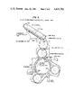
- FIG. 2 is a generalized depiction of a counterflow separated slot, defining various parameters
- FIG. 3A, 3B and 3C depict three representative forms of counterflow slots, herein termed "Type A”, “Type B", and “Type C” counterflow slots;
- FIG. 4 depicts an aeromechanical separator machine in accordance with the invention, which machine utilizes serpentine feed, employs five counterflow slots, two microdust removal points, and pinned and perforated cylinders;
- FIG. 5 depicts another machine embodiment in accordance with the invention employing high speed feed roll/feed plate input
- FIG. 6A is an end view of a typical perforated and pinned cylindrical wheel in accordance with the invention.
- FIG. 6B is a longitudinal section along line 6B--6B of FIG. 6A.
- FIG. 6C is a greatly enlarged view of a portion of the circumference of the wheel of FIG. 6A.
- a two-stage separation apparatus in accordance with the invention includes a conventional feed roller 10/feed plate 12 arrangement in combination with a toothed first stage individualizing and cleaning wheel or beater 14 of hollow cylindrical configuration. While the wheel 14 is illustrated as having teeth, hardened pins in a helical pattern may alternatively be employed. The rotational speed of the first stage wheel 14 may be in the range of from 50 to 5000 RPM, and is nominally around 3000 RPM.
- the wheel 14 is roughly similar to the licker-in of a conventional carding machine or the beater stage of an open-end spinning head, with, however, the important exception of perforations 16, which in accordance with the invention, allow flow radially into the wheel 14.
- Pneumatic or physical transport of raw stock 18 (for example, cotton tufts) into the feed roller 10/feed plate 12 is accomplished by any of a number of conventional techniques, for example, by a condenser arrangement.
- fiber is transferred as at point E to a rotating second stage wheel 72 by toothed- or pinned-wheel transfer or penumatic "doffing", or both. Finally, the fiber is removed or “doffed” as at 22 from the second stage for subsequent measurement or processing.
- Tufts of randomly oriented fiber 24 are gripped by the feed roll 10/feed plate 12 combination and engage teeth 26 of the first stage or beater wheel 14. This action combs the fibers 28 and imparts large impart forces preferentially to the large, dense particles in the fiber, striking them toward a trash tube 30 with trajectories between those represented at A and B. The fibers are hooked by the teeth 26 and quickly accelerated to the peripheral speed of the first stage wheel 14 when they are released from the gripped tuft.
- Conditioned inlet air 36 or other transport gas is directed toward the beater wheel 14 in a crossflow manner so that particles smaller than, for example, 500 ⁇ m aerodynamic equivalent diameter (AED), do not enter the trash tube 30. That is, particles having AED>500 ⁇ m are "knocked" across the inlet crossflow 36 into the trash tube 30. Particles having AED ⁇ 500 ⁇ m however move into a separation gap 42.
- the trajectory lines A and B permit aerodynamic definition of the particle size captured.
- the lower cut-off, AED 500 ⁇ m in this illustration, results from balances between the outward centrifugal and inward aerodynamic drag forces on the particles.
- One or more lint bars 38 may be employed to aid in the removal by preferentially holding fibers on the beater wheel 14 and causing more sharply accelerating flow 40 to accelerate trash particles outward into the separation gap 42.
- Trash particles thus removed and classified may then be measured by electro-optic 44 or gravimetric 46 means.
- a suitable electro-optic sensor employs continuous aerosol monitor (CAM) technique disclosed in Shofner et al U.S. Pat. No. 4,249,244.
- CAM continuous aerosol monitor
- Modified CAM sensors 44 have proven to measure the total trash mass or weight and to provide particle size classification or mass fraction analysis. These same particles may be captured on filter materials 46 for weighing and, in some cases classification, both using means well known in the art.
- microdust that is particles small than, for example AED ⁇ 50 ⁇ m
- a radially inward air flow component represented at 48.
- the inward flow 48 is controlled to preferred circumferential regions by a semi-cylindrical air blocking sleeve 50.
- the separated microdust is then pneumatically transported through a radial port 1 (52) and thence to an electro-optical 54 or gravimetric 56 weighing means. Suction is applied to the radial port 1 (52) to draw the air or other transport gas through the machine and, in particular, through the perforations 16.
- fibers whose AED's are also ⁇ 50 ⁇ m, do not enter the perforations 16 because of their length. Fiber fragments whose lengths are about the same diameter as the holes do enter and are properly classfied as microdust.
- a separation stripper 70 which defines the final cut in AED for the first stage. It is most important to note, in the vicinity of points C and D, that air is moving into the wheel 14 and into the dust tube 60. Larger particles move outward across or counter to the inward flow 70 and into the dust tube 60. This is one embodiment of the counter flow slot concept described in detail hereinafter with reference to FIGS. 2-6.
- Fiber is transferred to the second stage cylindrical wheel 72 at Point E.
- the peripheral velocity of the second stage cylinders 72 is much higher, and stronger release and separation forces can be applied. (Which, again, are distinct forces.)
- the density of the fiber on the second stage wheel 72 is relatively tenuous compared to the first stage wheel.
- a second counterflow slot is placed at point F. While the principles of counterflow slots are described in detail below with reference to FIGS. 2-6, it may here briefly be noted that large (e.g., AED>50 ⁇ m) particles removed by impaction and combing and whose momentum overcomes the inward flow drag are separated into the dust tube 76, 76' and combined with the dust from the first stage along the trajectory C.
- large (e.g., AED>50 ⁇ m) particles removed by impaction and combing and whose momentum overcomes the inward flow drag are separated into the dust tube 76, 76' and combined with the dust from the first stage along the trajectory C.
- a source G of blast air 80 is provided at a point between the point E where fiber is transferred to the second stage wheel 72 and the point 22 where the lint mat is doffed.
- the lint itself does not pass through the perforations, which are typically about 0.060 inch ( ⁇ 1.5 mm) in diameter and provide in the order of 25% open area.
- the lint whose AED ⁇ 50 ⁇ m, is held onto the cylinder 72 by the inward flows 78 and by the "hook" action of the teeth. Again, the length of the lint precludes its movement through the holes in the perforated wheels, even when the forces are very large, as with the microdust blast air G.
- Carding action is employed as at point H, and is commonly recognized as effective in microdust release.
- Conventional carding machines do not employ inward flows as at 84, or pulsating (i.e. acoustical) flows for microdust removal, as at 86.
- the radially inward flows 78 and 84 are provided by suitable holes between the teeth so that clean air or other transport gas may move first through the external pins 88 ("flats") into the perforated wheel 72.
- An exemplary electrodynamic force is provided by a static or DC voltage 92 applied between the pins 88 and the second-stage wheel 72.
- a static or DC voltage 92 applied between the pins 88 and the second-stage wheel 72.
- an alternating voltage in some cases more effectively causes release.
- undesirable electro-static foces which render less effective particle release or which cause fiber damage may require charge neutralization. This can be accomlished with electrical 92 or radioactive means.
- Microdust thus removed and separated is similarly transported by suction into radial Port 2 (94) and to the microdust sensing means, which may be electro-optic (54) or gravimetric (56).
- FIG. 1 in accordance with the invention there is provided a proper combination of various aeromechanical and electrodynamic forces, especially including radially inward, aerodynamic drag forces, for the controlled release and separation of foreign matter from fiber.
- the separation is into pre-determined aerodynamic equivalent diameter (AED) classifications such as (1) Trash: AED>500 ⁇ m; (2) Dust: 50 ⁇ m ⁇ AED ⁇ 500 ⁇ m; and (3) Microdust: AED ⁇ 50 ⁇ m.
- AED aerodynamic equivalent diameter
- This subclass is advantageously further classified by the CAM electro-optical method of U.S. Pat. No. 4,249,244. This CAM method permits E-0 classification of the trash and dust components as well.
- the resultant lint removed at 22 by centrifugal or aerodynamic forces has been cleaned, processed and blended.
- the fibers are generally individualized and are in an ideal state for electro-optical measurement as at 98, or for further processing, as for example, open-end spinning as described in J. I. Kotter, D. P. Thibodeaux, "Dust-Trash Removal by the SRRC Tuft-To-Yarn Processing System", Journal of Engineering for Industry, Vol. 101, No. 2, May, 1979. Fiber property measurements are discussed hereinafter.
- FIG. 1 embodies a number of basic principles and concepts in accordance with the invention whereby new and properly controlled forces are applied to remove and separate foreign matter from lint.
- One particularly significant aspect of the invention is the counterflow slot concept mentioned briefly with respect to FIG. 1 counter flow slots at C and F, and described in detail hereinafter with reference to FIGS. 2-6.
- the embodiments of FIGS. 2-6 emphasize aeromechanical release and separation.
- a counter flow slot is a slot-like conduit or opening wherein flow of different constituents occurs in opposite directions at the same time.
- air flows in one direction, and the relatively larger dust and trash particles (in contrast to microdust) flow in the opposite direction, i.e., counter to the airflow.
- FIG. 2 depicts the general structure and defines the basic parameters of counter flow slots.
- the actual counter flow slot into which dust and trash particles are thrown by rotational force of a representative wheel 112 is designated 100.
- the slot 100 is oriented generally tangentially to the wheel 112 and properly positioned with respect to the direction of rotation of the wheel 112.
- the slot 100 communicates with a collector tube 102 out of which dust and trash exit at 114.
- a pair of elongated openings 104 and 106 allow airflow to enter, which branches in two directions to flow in the slot 100 and the collector tube 102. It will be appreciated that this general structure is subject to numerous variations.
- FIG. 2 it will be appreciated that the cross-hatched boundary portions of the slot 100 run parallel to the axis of rotation of the main cylinder 112.
- the collector tube 102 inlet also runs axially, but its flow Q c is drawn into a round conduit 114 for the pneumatic transport of the dust plus trash to the disposal or measuring means, as for example, a CAM sensor 44 or 64, as in FIG. 1.
- W c width of the collector tube 102
- Fiber and foreign matter particles are thrown into the slot 100 by the rotational force of the cylindrical wheel 112 and move in a sense that is generally counter to the flow of air Q s into the slot 100.
- fibers have AED ⁇ 50 ⁇ m, typically, and, along with foreign matter particles having AED ⁇ 50 ⁇ m, are turned around and drawn back toward the cylinder 112 by the airflow Q s . Lint is thus recaptured by the pins or teeth of the cylinder 112 and carried with the cylindrical wheel 112 and carried with the cylindrical wheel 112.
- the aeromechanical separation principles of the basic counter flow slot of FIG. 2 may be embodied in a number of forms.
- three overall forms are herein designated Type A, Type B and Type C, and illustrated in FIGS. 3A, 3B and 3C, respectively.
- air or transport gas is drawn at 130 into a perforated main cylinder 132.
- the circumferential extent 131 in which slot air 130 flows is defined by a blocking sleeve 134.
- the Type C form illustrated in FIG. 3C results in a construction which is less expensive than the Type A form and about equally effective in the removal of foreign matter.
- the lint is pneumatically transported at 150 along with the foreign matter which has been removed by the action of a non-perforated main cylinder 152 in transfer from a feed or input cylinder 154. Particles are then subsequently separated from the lint in three mechanisms in FIG. 3C: (1) through a perforated wall 156 (Recall that the fiber density is low so that the particles have an opportunity to migrate through the tenuous fiber mass into the perforated wall.); (2) at the counterflow slot 158 (shown here as a single-entry slot); and (3) microdust and possibly dust into the perforated cylinder 162.
- the Type C embodiment of FIG. 3C provides a more economical construction for at least two major reasons.
- this adaptation may be retrofitted to a variety of existing lint-cleaning equipment for which perforated main cylinders would be prohibitively expensive and/or unavailable.
- FIG. 4 illustrates an embodiment of the invention which is constructed of practical elements and which has been thoroughly tested.
- Fiber is drawn by a belt/slide arrangement 200 into a conventional feed roll 202/feed plate 204 configuration.
- a first or opening cylinder 206 combs the fiber around the feed plate 204 and removes foreign matter, preferentially large foreign matter or trash, which is then separated into a first counter flow slot (CFS 1) 206, shown as a single entry slot.
- CFS 1 counter flow slot
- the fiber which is hooked onto the forward raked pins of the combing cylinder 206 is then transported into an input or feed cylinder 208 having pins 210 which intersect with pins of the combing cylinder 206.
- the fiber is transported in a serpentine fashion such that both sides of the fiber mat are acted upon or cleaned.
- the input cylinder 208 is typically moving at a much higher speed than the combing cylinder 206 and foreign matter is aeromechanically released and separated using a second counter flow slot (CFS 2), illustrated as a double-entry slot.
- CFS 2 second counter flow slot
- Vigorous aeromechanical separation 214 takes place at the inlet of the counterflow slot 216, shown here as a Type A slot as in FIG. 3A (air into cylinder slot) and provides a third opportunity for removal of foreign matter. In this case dust and trash are thrown out into a third counter flow slot (CFS 3) and microdust is drawn into the perforated cylinder 212 at 218.
- CFS third counter flow slot
- the lint is thus removed from the main cylinder 212 and thrown onto a second-stage worker cylinder 222 which then transports the fiber around for a second engagement with the main cylinder 212.
- the second engagement is not serpentine but is in the form of a high-speed feed roll 222/feed plate 224 combination.
- a fourth counterflow slot (CFS 4) 226 operates also as a Type A air into cylinder slot. Also, microdust is drawn into the perforated main cylinder 212 at 230.
- a fifth counterflow slot (CFS 5) 227 is a Type B (air over cylinder).
- the air 228 drawn into the slot is also used to pneumatically doff and transport the lint out of the system for subsequent processing or measurement use.
- FIG. 4 thus illustrates the application of five counterflow slots of various designs in a single machine.
- pins 210 between the combing 206 and feed 208 cylinders has been found advantageous for complete fiber transfer between these two cylinders and also because it affords a good opportunity to comb or align the fibers in addition to providing aeromechanical release and separation forces. It is of significance that the fiber fed into the main cylinder is less dense than in prior art machines and furthermore the fibers have been drawn or drafted by the two inlet stages.
- FIG. 5 shows another embodiment using the same aeromechanical separation equipment as for FIG. 4 but using a different feeding arrangement.
- the fiber is fed from the inlet cylinder 300 in a conventional feed roll 300/feed plate 302 arrangement. Fiber is more aggressively combed in this manner and in some cases the attendant higher fiber damage rates are acceptable in balance with the improved combing and release and separation of foreign matter.
- the serpentine pattern is retained for the combing cylinder 303 except that the stock feed roll 202/feet plate 204 of FIG. 4 has been eliminated to show yet another embodiment of the feed stages of the machine.
- the air or other transport gas fed into the machine at the counterflow slots 304, 306, 308 and at the inlets 309 and 311 may be controlled in its humidity and electrostatic charge quality so that the operation of the aeromechanical release and separation means can be on preferred states of the fiber with regard to humidity and static charge. That is, the air into the machine can be far more economically and accurately conditioned than the entire air in the work space, thus providing fundamental advantages for measurement and processing. It is furthermore clear that the humidity and electrostatic charge of the fiber may be different at each of the different processing stages simply by controlling the air fed into the system at the various counterflow slot points.
- a perforated belt-feed system 330 draws 332 conditioned air 334 through the feed table 336.
- Fiber from tightly compressed bales can be relaxed by first plucking small tufts from the mass and then transporting them to the feed table 336 of FIG. 5. This may also be easily done by replacing the feed table with a standard condenser which is well known in the art. Obviously, the air drawn into the condenser may be similarly conditioned as at 336 in FIG. 5. The fibers can be given preferential alignment and can be deposited in a more blended, more uniform mat.
- FIGS. 6A, 6B and 6C show in detail a typical perforated cylinder in accordance with the invention, and the method by which air is drawn into the perforated cylinder.
- FIG. 6C in particular illustrates the arrangement of the pins 402 and the perforation holes 404.
- Air is drawn into the holes 404 by a cylindrical blocking sleeve which slips into from the cylinder right-hand and as seen in FIG. 6B.
- FIG. 5 shows an end view of the blocking sleeve 34.
- the blocking sleeve axial slots cut at the preferred circumferential locations and draw microdust-laden air in, as in FIG. 4 (at 218, 230) or FIG. 5 (at 342, 344, 346). Air is drawn out of the cylinder by any suitable means.
- the pins are angled with respect to imaginary radial lines by an angle ⁇ , typically 9°; and the circumferential spacing s between pins is typically 0.1 inch.
- angle ⁇ typically 9°
- the circumferential spacing s between pins is typically 0.1 inch.
- the inside diameter a is 4.625 inches; the diameter b is 4.875 inches; the diameter c is 5.375 inches; the diameter d is 5.611 inches; the pin height e is 3.0 mm (0.118 inches); the diameter f is 1.0 inch; the diameter g is 2.0 inches; the spacing h is 1.0 inch; the spacing i is 1.25 inches; along the length of the cylinder the portion j has approximately eighty pins on a 0.1 inch spacing for a total of 8 inches, and arranged in a helical pattern; the cylinder length k is 91/8 inches; the dimension 1 is 11/8 inches; the dimension m is 3/8 inch; the dimension n is 1/2 inch; the dimension p is 3/4 inch; the dimension q is 1/8 inch; and the dimension r is 1/4 inch.
- the pins 402 have a diameter of 0.040 inch, and the holes 404 have a diameter of 0.060 inch.
- microdust-laden air 218, 230 is transported out of the internal parts of the main cylinder 212 and blocking sleeve 220 as described above and into a single pipe.
- the flow for the five counterflow separation slots of FIG. 4 may be either individually transported into measurement apparatus, such as electro-optical sensors 44, 64 illustrated in FIG. 1 or, may be combined into a single conduit 60.
- the individual flows Q s for the five slots in FIG. 4 are adjusted simply by providing variable restrictions in the flow lines, as is well known in the art.
- the electro-optical sensing means may be used to provide characterization of these components.
- the modified CAM sensor permits mass fraction resolution into perhaps eight sized channels, beginning at 50 ⁇ m.
- the aeromechanical separator of FIG. 4 basically has one, sharply-defined cut point at AED 50 ⁇ m. This is a simplification and in some measures an improvement over the embodiment of FIG. 1 where trash, dust and microdust all are aerodynamically defined. The requisite resolution of the dust and/or trash components is in this embodiment is advantageously performed with electro-optical measures.
- the cleaned, blended, and processed fiber 96 is pneumatically transported away from the MTM.
- fiber parameters include the lint feed rate, the fiber diameter distribution, which relates to maturity and fineness, and the length distribution, which is an important parameter determining the yarn properties, especially strength. From the length distribution one may determine the conventional specifications such as 21/2% span length, upper-half mean, or short fiber content of the fibers. Short fiber content, for example, the percentage weight below 1/2" in fiber length, is of significant importance currently because of the excessive ginning required to clean cotton harvested by the stripper method. This equipment entrains much more foreign matter into the seed cotton than prior harvesting methods. It is believed that increasing short fiber content is currently resulting in poorer quality yarn and less economical preparation thereof.
- FIGS. 1--3 and the preferred embodiments of FIGS. 4-6 teach a new method for removing foreign matter from lint. It is emphasized again that the teachings of this invention or extensions thereof are equally applicable to measurements of foreign matter and to its removal for improved processing purposes. It is envisioned for the latter application that higher speed, more efficient, and less damaging lint cleaning and other processing machinery can now evolve based on the principles of these teachings.
Abstract
Description
______________________________________
       Dia-                          Den-
       meter   Speed     Height
                               Pins  sity
Cylinders
       Inches  RPM       Inches
                               Angle #/in.sup.2
                                           Pattern
______________________________________
Combing
       3        10-300   1/4   9°
                                     16    Cir-
                                           cular
Inlet  3        60-3000  1/8   9°
                                     50    Cir-
                                           cular
Main   6       2000-4000 1/8   9°
                                     100   Helical
Workers
       3        50-5000  1/8   9°
                                     50    Helical
______________________________________
            Q.sub.s  L        W.sub.s
                                   Q.sub.c
                                         W.sub.c
Counterflow Slots
            CFM      in       in   CFM   in
______________________________________
1           3        3        1/2  5     3/4
2           10       2        1/2  5     3/4
3           25        11/2    1/2  5     3/4
4           15        11/2    1/2  5     3/4
5           35       1        3/4  5     1
______________________________________
Claims (13)
Priority Applications (1)
| Application Number | Priority Date | Filing Date | Title |
|---|---|---|---|
| US06/826,903 US4631781A (en) | 1982-09-30 | 1986-02-06 | Conditioned gas flow methods for processing and cleaning fiber, including aeromechanical and electrodynamic release and separation |
Applications Claiming Priority (2)
| Application Number | Priority Date | Filing Date | Title |
|---|---|---|---|
| US42860882A | 1982-09-30 | 1982-09-30 | |
| US06/826,903 US4631781A (en) | 1982-09-30 | 1986-02-06 | Conditioned gas flow methods for processing and cleaning fiber, including aeromechanical and electrodynamic release and separation |
Related Parent Applications (1)
| Application Number | Title | Priority Date | Filing Date |
|---|---|---|---|
| US06716175 Continuation | 1985-03-26 |
Publications (1)
| Publication Number | Publication Date |
|---|---|
| US4631781A true US4631781A (en) | 1986-12-30 |
Family
ID=27027841
Family Applications (1)
| Application Number | Title | Priority Date | Filing Date |
|---|---|---|---|
| US06/826,903 Expired - Lifetime US4631781A (en) | 1982-09-30 | 1986-02-06 | Conditioned gas flow methods for processing and cleaning fiber, including aeromechanical and electrodynamic release and separation |
Country Status (1)
| Country | Link |
|---|---|
| US (1) | US4631781A (en) |
Cited By (21)
| Publication number | Priority date | Publication date | Assignee | Title |
|---|---|---|---|---|
| US4858277A (en) * | 1987-10-09 | 1989-08-22 | Hergeth Hollingsworth Gmbh | Process and apparatus for cleaning and opening loose fiber stock, e.g. cotton |
| US4869060A (en) * | 1988-06-22 | 1989-09-26 | Wm. R. Stewart & Sons (Hacklemakers) Limited | Fiber opening devices |
| US4884395A (en) * | 1988-06-22 | 1989-12-05 | Wm. R. Stewart & Sons (Hacklemakers) Ltd. | Fibre opening devices |
| US5155886A (en) * | 1991-07-11 | 1992-10-20 | Texoma Machine, Inc. | Grid and cylinder air wash baffle wall for lint cleaner |
| US5241726A (en) * | 1990-05-29 | 1993-09-07 | Fratelli Marzoli & C. S.P.A. | Process and device for opening and cleaning fibrous material in an opener |
| US5321496A (en) * | 1990-03-14 | 1994-06-14 | Zellweger Uster, Inc. | Apparatus for monitoring trash in a fiber sample |
| US5365640A (en) * | 1992-03-06 | 1994-11-22 | Shlomo Sterin | Apparatus for sorting fibers |
| US5410401A (en) * | 1990-03-14 | 1995-04-25 | Zellweger Uster, Inc. | Methods and apparatus for mechanically and electronically correcting presentation of entities in a fluid flow |
| US5430301A (en) * | 1990-03-14 | 1995-07-04 | Zellweger Uster, Inc. | Apparatus and methods for measurement and classification of generalized neplike entities in fiber samples |
| US5469253A (en) * | 1990-03-14 | 1995-11-21 | Zellweger Uster, Inc. | Apparatus and method for testing multiple characteristics of single textile sample with automatic feed |
| US5539515A (en) * | 1990-03-14 | 1996-07-23 | Zellweger Uster, Inc. | Apparatus and methods for measurement and classification of trash in fiber samples |
| US5537868A (en) * | 1992-09-23 | 1996-07-23 | Zellweger Uster, Inc. | Direct control of fiber testing performance parameters by application of controlled conditioned gas flows |
| US5613279A (en) * | 1996-02-16 | 1997-03-25 | Kings Mountain Textile Machinery Company | Apparatus for removing contaminants from raw cotton |
| US5676177A (en) * | 1994-11-02 | 1997-10-14 | Shofner Engineering Associates, Inc. | Method for optimally processing materials in a machine |
| US5822972A (en) * | 1997-06-30 | 1998-10-20 | Zellweger Uster, Inc. | Air curtain nep separation and detection |
| US5890264A (en) * | 1997-10-06 | 1999-04-06 | Premier Polytronics Limited | Aeromechanical individualizer |
| US5910598A (en) * | 1994-11-02 | 1999-06-08 | Shofner Engineering Associates, Inc. | Modular process zone and personnel zone environmental control with dedicated air jet cleaning |
| US6029316A (en) * | 1997-01-08 | 2000-02-29 | Premier Polytronics Limited | Environmental conditioning methods and apparatus for improved materials testing: rapidcon and rapidair |
| US6397437B1 (en) | 1999-09-16 | 2002-06-04 | Shofner Engineering Associates, Inc. | Ultra rapid conditioning of cotton fiber for testing and processing |
| US20130037329A1 (en) * | 2010-05-06 | 2013-02-14 | Uster Technologies Ag | Impurity Weight Measurement |
| CN114687020A (en) * | 2020-12-30 | 2022-07-01 | 苏州多道自动化科技有限公司 | Impurity removing and carding system of rotor spinning machine AI based on impurity detection |
Citations (4)
| Publication number | Priority date | Publication date | Assignee | Title |
|---|---|---|---|---|
| US3136005A (en) * | 1958-12-04 | 1964-06-09 | Whitin Machine Works | Card clothing |
| US3169278A (en) * | 1960-09-12 | 1965-02-16 | Daiwa Spinning Co Ltd | Carding machines |
| US4135276A (en) * | 1976-08-03 | 1979-01-23 | Schubert & Salzer | Apparatus for removing impurities from fibrous material |
| US4345356A (en) * | 1979-10-02 | 1982-08-24 | Schubert & Salzer | Mechanism for eliminating impurities from fibrous material, in particular cotton |
-
1986
- 1986-02-06 US US06/826,903 patent/US4631781A/en not_active Expired - Lifetime
Patent Citations (4)
| Publication number | Priority date | Publication date | Assignee | Title |
|---|---|---|---|---|
| US3136005A (en) * | 1958-12-04 | 1964-06-09 | Whitin Machine Works | Card clothing |
| US3169278A (en) * | 1960-09-12 | 1965-02-16 | Daiwa Spinning Co Ltd | Carding machines |
| US4135276A (en) * | 1976-08-03 | 1979-01-23 | Schubert & Salzer | Apparatus for removing impurities from fibrous material |
| US4345356A (en) * | 1979-10-02 | 1982-08-24 | Schubert & Salzer | Mechanism for eliminating impurities from fibrous material, in particular cotton |
Cited By (24)
| Publication number | Priority date | Publication date | Assignee | Title |
|---|---|---|---|---|
| US4858277A (en) * | 1987-10-09 | 1989-08-22 | Hergeth Hollingsworth Gmbh | Process and apparatus for cleaning and opening loose fiber stock, e.g. cotton |
| US4869060A (en) * | 1988-06-22 | 1989-09-26 | Wm. R. Stewart & Sons (Hacklemakers) Limited | Fiber opening devices |
| US4884395A (en) * | 1988-06-22 | 1989-12-05 | Wm. R. Stewart & Sons (Hacklemakers) Ltd. | Fibre opening devices |
| US6188479B1 (en) | 1990-03-14 | 2001-02-13 | Zellweger Uster, Inc. | Methods and apparatus for mechanically and electronically correcting presentation of entities in a fluid flow |
| US5321496A (en) * | 1990-03-14 | 1994-06-14 | Zellweger Uster, Inc. | Apparatus for monitoring trash in a fiber sample |
| US5410401A (en) * | 1990-03-14 | 1995-04-25 | Zellweger Uster, Inc. | Methods and apparatus for mechanically and electronically correcting presentation of entities in a fluid flow |
| US5430301A (en) * | 1990-03-14 | 1995-07-04 | Zellweger Uster, Inc. | Apparatus and methods for measurement and classification of generalized neplike entities in fiber samples |
| US5469253A (en) * | 1990-03-14 | 1995-11-21 | Zellweger Uster, Inc. | Apparatus and method for testing multiple characteristics of single textile sample with automatic feed |
| US5539515A (en) * | 1990-03-14 | 1996-07-23 | Zellweger Uster, Inc. | Apparatus and methods for measurement and classification of trash in fiber samples |
| US5241726A (en) * | 1990-05-29 | 1993-09-07 | Fratelli Marzoli & C. S.P.A. | Process and device for opening and cleaning fibrous material in an opener |
| US5155886A (en) * | 1991-07-11 | 1992-10-20 | Texoma Machine, Inc. | Grid and cylinder air wash baffle wall for lint cleaner |
| US5365640A (en) * | 1992-03-06 | 1994-11-22 | Shlomo Sterin | Apparatus for sorting fibers |
| US5537868A (en) * | 1992-09-23 | 1996-07-23 | Zellweger Uster, Inc. | Direct control of fiber testing performance parameters by application of controlled conditioned gas flows |
| US5676177A (en) * | 1994-11-02 | 1997-10-14 | Shofner Engineering Associates, Inc. | Method for optimally processing materials in a machine |
| US5910598A (en) * | 1994-11-02 | 1999-06-08 | Shofner Engineering Associates, Inc. | Modular process zone and personnel zone environmental control with dedicated air jet cleaning |
| US5613279A (en) * | 1996-02-16 | 1997-03-25 | Kings Mountain Textile Machinery Company | Apparatus for removing contaminants from raw cotton |
| US6029316A (en) * | 1997-01-08 | 2000-02-29 | Premier Polytronics Limited | Environmental conditioning methods and apparatus for improved materials testing: rapidcon and rapidair |
| US5822972A (en) * | 1997-06-30 | 1998-10-20 | Zellweger Uster, Inc. | Air curtain nep separation and detection |
| US5890264A (en) * | 1997-10-06 | 1999-04-06 | Premier Polytronics Limited | Aeromechanical individualizer |
| US6397437B1 (en) | 1999-09-16 | 2002-06-04 | Shofner Engineering Associates, Inc. | Ultra rapid conditioning of cotton fiber for testing and processing |
| US6604259B2 (en) | 1999-09-16 | 2003-08-12 | Shofner Engineering Associates, Inc. | Ultra rapid conditioning of cotton fiber for testing and processing |
| US20130037329A1 (en) * | 2010-05-06 | 2013-02-14 | Uster Technologies Ag | Impurity Weight Measurement |
| CN114687020A (en) * | 2020-12-30 | 2022-07-01 | 苏州多道自动化科技有限公司 | Impurity removing and carding system of rotor spinning machine AI based on impurity detection |
| CN114687020B (en) * | 2020-12-30 | 2024-01-12 | 苏州多道自动化科技有限公司 | Impurity detection-based impurity removal carding system of rotor spinning machine AI |
Similar Documents
| Publication | Publication Date | Title |
|---|---|---|
| US4512060A (en) | Apparatus and methods for aeromechanical and electrodynamic release and separation of foreign matter from fiber | |
| US4686744A (en) | Methods for aeromechanical and electrodynamic release and separation of foreign matter from fiber | |
| US4631781A (en) | Conditioned gas flow methods for processing and cleaning fiber, including aeromechanical and electrodynamic release and separation | |
| US5483844A (en) | Needle-based apparatus for individualizing single fibers and other textile entities for testing purposes | |
| US5890264A (en) | Aeromechanical individualizer | |
| US8112845B2 (en) | Method and apparatus for separating foreign matter from fibrous material | |
| AU2017202132B2 (en) | Improved lint cleaner | |
| US5546635A (en) | Apparatus for cleaning and opening fiber tufts | |
| Omonov et al. | Analysis of changes in fiber properties in processes opening, cleaning and carding | |
| Mangialardi Jr et al. | Field evaluations of air and saw lint cleaning systems | |
| DE10144211A1 (en) | Device on a card for cleaning and opening fiber material | |
| Frydrych et al. | Trends of AFIS application in research and industry | |
| Rodionov et al. | Innovative developments in the theory and technology of production of single and twisted yarn containing flax fibers | |
| US3320641A (en) | Method for continuous, high-speed processing and cleaning of fibers | |
| Smith | Yarn Production and Properties | |
| Göktepe et al. | The effect of the licker-in speed on fibre properties on modern carding machines with a triple licker-in | |
| DE10110825A1 (en) | Carding machine has suction openings in the drum cover under the drum for the extraction of detached fibers and debris from the drum clothing between the doffer and the licker-in | |
| US3391430A (en) | Apparatus for continuous, high-speed processing and cleaning of fibers | |
| Rousselle et al. | Heat treatment of cotton: effect on endotoxin content, fiber and yarn properties, and processability | |
| US3345878A (en) | Card assembly sampler | |
| Mangialardi Jr | Lint cleaning options to preserve fiber quality at gins | |
| Färber et al. | Relationships between Cotton fiber properties and mill processing results from bale to card sliver | |
| Le | Fiber quality properties produced by saw-type lint cleaners | |
| Hughs et al. | Fiber quality from a combination gin-lint cleaner | |
| Yeshzhanov et al. | The influence of increasing the productivity of the carding machine on the quality indicators of the card sliver |
Legal Events
| Date | Code | Title | Description |
|---|---|---|---|
| STCF | Information on status: patent grant |
Free format text: PATENTED CASE |
|
| AS | Assignment |
Owner name: ZELLWEGER USTER TECHNOLOGIES, INC., A CORP. OF NOR Free format text: ASSIGNMENT OF ASSIGNORS INTEREST.;ASSIGNOR:SHOFNER ENGINEERING ASSOCIATES, INC.;REEL/FRAME:005043/0489 Effective date: 19890320 |
|
| FEPP | Fee payment procedure |
Free format text: PAT HLDR NO LONGER CLAIMS SMALL ENT STAT AS INDIV INVENTOR (ORIGINAL EVENT CODE: LSM1); ENTITY STATUS OF PATENT OWNER: LARGE ENTITY Free format text: PAYOR NUMBER ASSIGNED (ORIGINAL EVENT CODE: ASPN); ENTITY STATUS OF PATENT OWNER: LARGE ENTITY |
|
| FPAY | Fee payment |
Year of fee payment: 4 |
|
| FEPP | Fee payment procedure |
Free format text: PAYER NUMBER DE-ASSIGNED (ORIGINAL EVENT CODE: RMPN); ENTITY STATUS OF PATENT OWNER: LARGE ENTITY Free format text: PAYOR NUMBER ASSIGNED (ORIGINAL EVENT CODE: ASPN); ENTITY STATUS OF PATENT OWNER: LARGE ENTITY |
|
| FPAY | Fee payment |
Year of fee payment: 8 |
|
| AS | Assignment |
Owner name: ZELLWEGER USTER, INC., TENNESSEE Free format text: CHANGE OF NAME;ASSIGNOR:ZELLWEGER USTER TECHNOLOGIES, INC.;REEL/FRAME:008167/0205 Effective date: 19910611 |
|
| FPAY | Fee payment |
Year of fee payment: 12 |
|
| AS | Assignment |
Owner name: USTER TECHNOLOGIES, INC., TENNESSEE Free format text: CHANGE OF NAME;ASSIGNOR:ZELLWEGER USTER, INC.;REEL/FRAME:014154/0603 Effective date: 20030128 |