US4635471A - Hardness testing device for pipes - Google Patents
Hardness testing device for pipes Download PDFInfo
- Publication number
- US4635471A US4635471A US06/819,415 US81941586A US4635471A US 4635471 A US4635471 A US 4635471A US 81941586 A US81941586 A US 81941586A US 4635471 A US4635471 A US 4635471A
- Authority
- US
- United States
- Prior art keywords
- testing
- head
- hardness
- work piece
- positioning
- Prior art date
- Legal status (The legal status is an assumption and is not a legal conclusion. Google has not performed a legal analysis and makes no representation as to the accuracy of the status listed.)
- Expired - Fee Related
Links
- 238000007542 hardness measurement Methods 0.000 title claims description 15
- 238000012360 testing method Methods 0.000 claims abstract description 52
- 239000000463 material Substances 0.000 claims abstract description 12
- 230000007246 mechanism Effects 0.000 claims abstract description 4
- 238000003801 milling Methods 0.000 claims description 15
- 239000003381 stabilizer Substances 0.000 claims description 11
- 230000000712 assembly Effects 0.000 claims description 6
- 238000000429 assembly Methods 0.000 claims description 6
- 230000004913 activation Effects 0.000 claims description 4
- 238000000034 method Methods 0.000 claims description 4
- 238000010998 test method Methods 0.000 claims description 2
- 238000004891 communication Methods 0.000 claims 2
- 238000004140 cleaning Methods 0.000 abstract description 2
- 238000010586 diagram Methods 0.000 description 4
- 230000003213 activating effect Effects 0.000 description 3
- 238000005520 cutting process Methods 0.000 description 2
- 229910003460 diamond Inorganic materials 0.000 description 2
- 239000010432 diamond Substances 0.000 description 2
- 238000006073 displacement reaction Methods 0.000 description 2
- 230000009977 dual effect Effects 0.000 description 2
- 238000002360 preparation method Methods 0.000 description 2
- 230000008569 process Effects 0.000 description 2
- 230000035945 sensitivity Effects 0.000 description 2
- 238000004804 winding Methods 0.000 description 2
- 230000001133 acceleration Effects 0.000 description 1
- 230000006835 compression Effects 0.000 description 1
- 238000007906 compression Methods 0.000 description 1
- 238000010276 construction Methods 0.000 description 1
- 230000008878 coupling Effects 0.000 description 1
- 238000010168 coupling process Methods 0.000 description 1
- 238000005859 coupling reaction Methods 0.000 description 1
- 238000013101 initial test Methods 0.000 description 1
- 230000010354 integration Effects 0.000 description 1
- 238000005461 lubrication Methods 0.000 description 1
- 230000000717 retained effect Effects 0.000 description 1
- 230000001360 synchronised effect Effects 0.000 description 1
- 238000004154 testing of material Methods 0.000 description 1
- 238000012956 testing procedure Methods 0.000 description 1
Images


Classifications
-
- G—PHYSICS
- G01—MEASURING; TESTING
- G01N—INVESTIGATING OR ANALYSING MATERIALS BY DETERMINING THEIR CHEMICAL OR PHYSICAL PROPERTIES
- G01N3/00—Investigating strength properties of solid materials by application of mechanical stress
- G01N3/40—Investigating hardness or rebound hardness
- G01N3/42—Investigating hardness or rebound hardness by performing impressions under a steady load by indentors, e.g. sphere, pyramid
-
- G—PHYSICS
- G01—MEASURING; TESTING
- G01N—INVESTIGATING OR ANALYSING MATERIALS BY DETERMINING THEIR CHEMICAL OR PHYSICAL PROPERTIES
- G01N2203/00—Investigating strength properties of solid materials by application of mechanical stress
- G01N2203/0098—Tests specified by its name, e.g. Charpy, Brinnel, Mullen
-
- Y—GENERAL TAGGING OF NEW TECHNOLOGICAL DEVELOPMENTS; GENERAL TAGGING OF CROSS-SECTIONAL TECHNOLOGIES SPANNING OVER SEVERAL SECTIONS OF THE IPC; TECHNICAL SUBJECTS COVERED BY FORMER USPC CROSS-REFERENCE ART COLLECTIONS [XRACs] AND DIGESTS
- Y10—TECHNICAL SUBJECTS COVERED BY FORMER USPC
- Y10T—TECHNICAL SUBJECTS COVERED BY FORMER US CLASSIFICATION
- Y10T409/00—Gear cutting, milling, or planing
- Y10T409/30—Milling
- Y10T409/303864—Milling with means to weigh or test work or product
Definitions
- U.S. Pat. No. 2,126,175 discloses a testing machine that determines hardness of material by speed and pressure required on a drill that engages the material.
- a hardness tester for pipes that provides an automatic positioning and holding of a work piece for testing and a pre-programmed, self-correcting prositioning of a multi-equipped testing head.
- the testing head combines both a cleaning and hardness testing function in a single configuration that has a pre-programmed controlled position by synchronized multiple servodrive motors in a position feed back configuration.
- a variety of pipes sizes and materials can be tested continuously in an automatic manner.
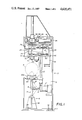
- FIG. 1 is a side elevation of a hardness testing device
- FIG. 2 is a front elevation of the hardness testing device
- FIG. 3 is an enlarged cross sectional view of a testing head
- FIG. 4 is an enlarged partial cross section of a milling head
- FIG. 5 is a block flow diagram of the testing head electronic control
- FIG. 6 is a block flow diagram of the pipe clamping electronic control mechanism
- FIG. 7 is a block diagram of a control unit and motor driven system
- FIG. 9 is an enlarged cross sectional view of a clamping load cell assembly.
- a hardness tester can be seen in FIGS. 1 and 2 of the drawings comprising a generally C-shaped frame configuration 10 having a base 11, vertical frame members 12 and 13 with right angularly extending head support framework 14 in oppositely disposed relation to said base 10.
- a work piece support and positioning stand 15 has a structural I-shaped member 16 from which multiple support links 17 and 18 extend.
- the links are pivoted to one another at 19 with links 17 being pivotally secured at one end to and extending from the stand 15.
- the free ends of the links 18 are pivoted to a work piece fixture 20 having a pair of upstanding support brackets 20A and 20B, the upper surfaces of which are tapered longitudinally from their oppositely disposed outer ends.
- a piston rod P of a piston and cylinder assembly P' is secured to the pivot 19 for reciprocation of the links as indicated by the broken lines in FIG. 1 of the drawings.
- the fixture 20 is movably positioned in a pair of spaced vertically aligned guide tracks 21 via guides 22 secured thereto.
- a testing and milling head assembly 23 is positioned within the head support framework 14 and is generally characterized by its ability to move on both a vertical and horizontal plane separately or simultaneously.
- the head assembly 23 has a stabilizer frame 24 with a pair of vertical guide shoes 25 positioned on either side thereof as best seen in FIG. 2 of the drawings.
- the guide shoes 25 are registrable within said vertically aligned guide tracks 21 as hereinbefore described.
- a vertical drive motor assembly 33 is secured within the head support framework 14 above and secured to the stabilizer frame 24.
- the vertical drive motor assembly comprises a motor 34 having a drive shaft 35 engaging a vertical ball jack 36 as is well known in the art.
- the vertical ball jack 36 has an activation shaft 37 that is secured to a bracket 38 on the upper side of the stabilizer frame 24.
- Horizontal movement of the test head support assembly 30 is achieved by activating the horizontal motor 26 with the corresponding movement of the screw follower 28 and support assembly 30 on the guide tracks 31 as indicated by the arrows in FIG. 1 of the drawings.
- a pair of clamping load cell assemblies 80 can be seen each having a main support arm 81 with an adjustable bracket 82.
- a limit switch 83 extends from the adjustable bracket 82.
- a load cell support bracket 84 is secured to the main support arm 81 and is apertured at 85 to receive a plunger 86 supported by bearings 87.
- the plunger 86 has a tapered top cap 88 that movably engages a limit switch follower 89.
- a clamping load cell 90 (manufactured by Houston Scientific International Inc., Model No. 1250) is positioned around the plunger 86 by a force washer 91 and held in place by a pair of retainer rings 92 and 93 separated by an adjustable shim 94.
- a spring washer 95 is positioned between the load cell 90 and support bracket 84 which allows for retraction of the clamping load cell 90 within the retainer rings 92 and 93.
- the timing sequence combined with the rate of displacement of the testing head support assembly 30 allows the controller (PC) to determine distance traveled upon initial contact by a nose piece 96 and compression of the clamping load cell 90 on which it is retained.
- the spring washer 95 is overcome allowing the clamping load cells 90 to retract within the retaining rings 93 and 92 as hereinbefore described.
- a milling head assembly 40 is positioned within the head support assembly 30 and can best be seen in FIG. 4 of the drawings having a head drive pulley 41 and central drive spindle 42 rotatably positioned within a main body member 43 having apertured upper and lower closure plates 44 and 45.
- Bearing assemblies 46 and associated lubrication passages 47 are positioned in closure plates 44 and 45 as will be well understood by those skilled in the art.
- a cutting tool 48 having a shank 49 is secured within a tool holder 50 defining the end of the spindle 42 and has a locking set screw 51 that secures the cutting tool 48 within the tool holder 50.
- An access plug 52 is aligned with said set screw in the main body member 43.
- An axial bore 53 extending downwardly from the spindle top is threaded at its lower end 54.
- a mill head drive motor 55 is secured to the test head support assembly 30 having a drive shaft 56 and a pulley 57 on the end thereof.
- a drive belt 58 communicates between the pulley 57 and said head drive pulley 41 providing rotation to the same.
- the control of the entire testing sequence which includes positioning and elevation of the test pipe (P), the vertical and horizontal movement of the testing and milling head assembly 23 is servo-controlled by a GE Series Six Programmable Controller (PC), Part No. 1C600CP241A and a GE Axis Positioning Module (APM) Type 1, part No. 1C600 BF915C via a Gould Inc. servodrive system (CLX).
- PC GE Series Six Programmable Controller
- API GE Axis Positioning Module
- CLX Gould Inc. servodrive system
- the axis positioning module is an intelligent, fully programmable single axis positioning controller integrated into the PC system.
- the APM provides a real time interface between the PC and a servo-controlled axis. Due to the complete integration of the APM into the PC system, the PC provides a predictable yet flexible axis control capability.
- the APM is distinguished by its use of resolvers (R) to provide postion feedback and by the programming of velocity and acceleration in terms of rates.
- the resolver (R) can be seen in FIGS. 7 and 8 of the drawings as a rotary transformer in which the phase relationship between its primary windings and secondary windings is controlled by the shaft position.
- Two primary coils, 90° mechanically and electrically out of phase, are located on a stator.
- a secondary coil (C) rotates with the rotor shaft (RS).
- the APM provides two excition signals identical in amplitude but 90° out of phase to the two stator coils; the phase angle (PA) of the voltage induced in the secondary coil is directly proportional to the mechanical shaft angle as will be well understood by those skilled in the art.
- the APM is positioned in a Series Six I/O rack where it is serviced by the Series Six Central Processing Unit (CPU) in the course of a normal CPU scan.
- the CPU communicates with the APM via a I/O bus using standard Series Six protocol.
- the APM translates the positioning commands received from the CPU into a position versus time profile, determines the current position of the axis using the input from a positioned feed back device, in this case a resolver, and compares it with the command position indicated by the profile.
- the profile is accomplished through software programming.
- This process results in a velocity command output to a servo-drive which moves the axis or axes.
- the CLX Servo Drive System consists of servo amplifier modules and power supply. Each amplifier module is capable of controlling one DC servo motor. Three motors that would be controlled by the CLX Servo Drive are the motor 34 of the vertical drive assembly, the motor 61 of the hardness testing device and motor 26 of the heat testing assembly 23.
- All external signals are fed into the amplifier module, see FIG. 6 of the drawings, via a removable personality board. Compensation for specific motor parameters (tack voltage, velocity command, input sensitivity, etc.) as well as selection of internal amplifier options (accel-decel, dual velocity command input sensitivity, etc.) are accessible on the personality board.
- the motor velocity command and tachomoeter feedback(T) are summed and amplified to become the current reference, see FIG. 7 of the drawings.
- the inner current loop then delivers the current error signal by summing the current reference with the current feeback.
- the polarity and amplitude of the current error signal is representative of the current delivered to the motor in question.
- the three axis control can be achieved with the proper positioning and clamping of the pipe(P) in the testing position, engagement and operation of the milling head 40 to mill a section of the pipe(P) so that the hardness testing head 59 can be positioned in the same space to achieve an accurate test of the pipe by the engagement of the testing load cell 72 via the plunger shaft 73 and diamond penetrator 74 onto the pipe(P).
- the clamping load cell 76 determines proper positioning of the test head assembly and a pre-determined clamp load factor on the pipe so that accurate hardness testing can be done.
- FIG. 6 of the drawings a block flow diagram is shown of the dual clamping load cell configuration. Output from the load cells are directed through strain gauge conditioners to the microprocessor which process the data information from a variety of other sources and outputs to the servo drive controller (CLX) which in turn drives the servomotors for position control as hereinbefore described.
- CLX servo drive controller
- the PC is indicated in the drawings of FIGS. 5 and 6 as the micro-processor block which connects to all positioning and activation functions.
- the testing device of this invention combines a unique clamping and testing load cell head configuration with a compact fully programmable positioning and activation control system that is fully adjustable to various pipe size and construction characteristics while maintaining a rapid, multi-step test sequence procedure insuring accurate, reliable test results within a continuous or batch material testing configuration environment.
Abstract
A hardness tester for pipes comprising a positioning mechanism that presents the pipe to a multiple purpose testing head having a pre-programmed proportional control configuration that independently engages the pipe and determines the pipes relative position to that of the program controlled testing head which contains independent pre-programmed testing heads. The pipe is prepared for testing by cleaning a small test portion of the pipe, engagement of a load cell assembly to the clean pipe portion determining material hardness.
Description
1. Technical Field
Devices of this type have used a variety of different and separate testing procedures to clean a small portion of the material to be tested and then determine the hardness of the material which is critically important in determining use characteristics and requirements.
2. Description of the Prior Art
Prior art devices of this type have relied on a variety of different holding and testing configurations. See for example U.S. Pat. Nos. 3,020,752, 2,126,175 and 2,690,702.
In U.S. Pat. No. 3,020,752, a device is disclosed that uses electromagnets to stabilize and hold the test piece in position for a movable hardness tester.
U.S. Pat. No. 2,126,175 discloses a testing machine that determines hardness of material by speed and pressure required on a drill that engages the material.
In U.S. Pat. No. 2,690,702, a combined testing device for use on materials is shown.
A hardness tester for pipes that provides an automatic positioning and holding of a work piece for testing and a pre-programmed, self-correcting prositioning of a multi-equipped testing head. The testing head combines both a cleaning and hardness testing function in a single configuration that has a pre-programmed controlled position by synchronized multiple servodrive motors in a position feed back configuration. A variety of pipes sizes and materials can be tested continuously in an automatic manner.
FIG. 1 is a side elevation of a hardness testing device;
FIG. 2 is a front elevation of the hardness testing device;
FIG. 3 is an enlarged cross sectional view of a testing head;
FIG. 4 is an enlarged partial cross section of a milling head;
FIG. 5 is a block flow diagram of the testing head electronic control;
FIG. 6 is a block flow diagram of the pipe clamping electronic control mechanism;
FIG. 7 is a block diagram of a control unit and motor driven system;
FIG. 8 is a graphic representation of a resolver; and
FIG. 9 is an enlarged cross sectional view of a clamping load cell assembly.
A hardness tester can be seen in FIGS. 1 and 2 of the drawings comprising a generally C-shaped frame configuration 10 having a base 11, vertical frame members 12 and 13 with right angularly extending head support framework 14 in oppositely disposed relation to said base 10. A work piece support and positioning stand 15 has a structural I-shaped member 16 from which multiple support links 17 and 18 extend. The links are pivoted to one another at 19 with links 17 being pivotally secured at one end to and extending from the stand 15. The free ends of the links 18 are pivoted to a work piece fixture 20 having a pair of upstanding support brackets 20A and 20B, the upper surfaces of which are tapered longitudinally from their oppositely disposed outer ends. A piston rod P of a piston and cylinder assembly P' is secured to the pivot 19 for reciprocation of the links as indicated by the broken lines in FIG. 1 of the drawings. The fixture 20 is movably positioned in a pair of spaced vertically aligned guide tracks 21 via guides 22 secured thereto. A testing and milling head assembly 23 is positioned within the head support framework 14 and is generally characterized by its ability to move on both a vertical and horizontal plane separately or simultaneously. The head assembly 23 has a stabilizer frame 24 with a pair of vertical guide shoes 25 positioned on either side thereof as best seen in FIG. 2 of the drawings. The guide shoes 25 are registrable within said vertically aligned guide tracks 21 as hereinbefore described.
A horizontal drive motor 26 is secured to the stabilizer frame 24 and has a threaded screw drive shaft 27 extending outwardly therefrom. A screw follower 28 is positioned on the shaft 27 and has a vertically disposed frame member 29 extending downwardly therefrom and secured to a movable testing head support assembly 30. A pair of horizontally positioned guide tracks 31 are longitudinally aligned on the testing head support assembly 30 and register with correspondingly positioned guide members 32 extending downwardly from the stabilizer frame 24.
A vertical drive motor assembly 33 is secured within the head support framework 14 above and secured to the stabilizer frame 24. The vertical drive motor assembly comprises a motor 34 having a drive shaft 35 engaging a vertical ball jack 36 as is well known in the art. The vertical ball jack 36 has an activation shaft 37 that is secured to a bracket 38 on the upper side of the stabilizer frame 24.
It will be evident from the above description that by activating the vertical drive motor 34 the shaft 37 will advance downwardly from the position indicated in FIG. 1 of the drawings moving the attached stabilizer frame 24 in the guide tracks 21 along with it.
Horizontal movement of the test head support assembly 30 is achieved by activating the horizontal motor 26 with the corresponding movement of the screw follower 28 and support assembly 30 on the guide tracks 31 as indicated by the arrows in FIG. 1 of the drawings.
Referring now to FIGS. 2 and 9 of the drawings, a pair of clamping load cell assemblies 80 can be seen each having a main support arm 81 with an adjustable bracket 82. A limit switch 83 extends from the adjustable bracket 82. A load cell support bracket 84 is secured to the main support arm 81 and is apertured at 85 to receive a plunger 86 supported by bearings 87. The plunger 86 has a tapered top cap 88 that movably engages a limit switch follower 89. A clamping load cell 90 (manufactured by Houston Scientific International Inc., Model No. 1250) is positioned around the plunger 86 by a force washer 91 and held in place by a pair of retainer rings 92 and 93 separated by an adjustable shim 94. A spring washer 95 is positioned between the load cell 90 and support bracket 84 which allows for retraction of the clamping load cell 90 within the retainer rings 92 and 93.
In operation, the clamping load cell assemblies 80 determine initial test material registration and sense the proper clamping load prior to material preparation for testing. The clamping load cell assemblies 80 are interconnected in the test procedure as is shown in FIG. 6 of the drawings. Upon initial vertical displacement of the testing head support assembly 30, the plunger 86 engages the test material and moves upwardly activating the limit switch 83 starting a timing sequence in a controller (PC) (which will be described in greater detail later).
The timing sequence combined with the rate of displacement of the testing head support assembly 30 allows the controller (PC) to determine distance traveled upon initial contact by a nose piece 96 and compression of the clamping load cell 90 on which it is retained.
As the proper predetermined clamping load is achieved, the spring washer 95 is overcome allowing the clamping load cells 90 to retract within the retaining rings 93 and 92 as hereinbefore described.
Once the limit switch assemblies 83 and clamping load cells 90 have satisfied all pre-programmed parameters as determined by the controller (PC) the material preparation and testing sequence can begin as will be hereinafter described.
A milling head assembly 40 is positioned within the head support assembly 30 and can best be seen in FIG. 4 of the drawings having a head drive pulley 41 and central drive spindle 42 rotatably positioned within a main body member 43 having apertured upper and lower closure plates 44 and 45. Bearing assemblies 46 and associated lubrication passages 47 are positioned in closure plates 44 and 45 as will be well understood by those skilled in the art.
A cutting tool 48 having a shank 49 is secured within a tool holder 50 defining the end of the spindle 42 and has a locking set screw 51 that secures the cutting tool 48 within the tool holder 50. An access plug 52 is aligned with said set screw in the main body member 43.
An axial bore 53 extending downwardly from the spindle top is threaded at its lower end 54. A mill head drive motor 55 is secured to the test head support assembly 30 having a drive shaft 56 and a pulley 57 on the end thereof. A drive belt 58 communicates between the pulley 57 and said head drive pulley 41 providing rotation to the same.
Referring now to FIG. 3 of the drawings, a hardness testing head assembly 59 can be seen comprising a two part housing 60A and 60B. A DC servodrive motor 61 is secured to the housing 60B and drives a gear box 62 within the housing via a coupling 63. A bearing assembly 64 supports an output shaft 65 which is axially aligned within the housings 60A and 60B. The shaft 65 is threaded and has a ball screw assembly 66 positioned thereon. A load cell stabilizer 67 is movably positioned within the housing 60A on stabilizer guide rods 68 that extend through slide bearings 69 in oppositely disposed bores 70 within the stabilizer 67. Each of the guide rods 68 have a disc-like stop 71 on its free end and is secured to the housing 60B at its opposite end. A testing load cell 72 is secured to the stabilizer 67 in axial alignment with the shaft 65 and has a plunger shaft 73 extending downwardly therefrom. The testing load cell 72 is well known in the art and in this example is manufactured by Houston Scientific International, Inc. Model 1350. The plunger shaft 73 extends in an opening in the housing 60A and has a diamond penetrator 74 secured to the end thereof. A clamping load cell assembly 75 is secured to the lower end of the housing 60A around the plunger shaft 73. The clamping load cell assembly comprising clamping load cell 76 manufactured by Houston Scientific International, Inc., Model 1250 held in positioned by a force washer 77 and a load cell retaining ring 78 secured to the housing by fasteners F.
Referring now to FIGS. 5, 6, 7 and 8 of the drawings, the control of the entire testing sequence which includes positioning and elevation of the test pipe (P), the vertical and horizontal movement of the testing and milling head assembly 23 is servo-controlled by a GE Series Six Programmable Controller (PC), Part No. 1C600CP241A and a GE Axis Positioning Module (APM) Type 1, part No. 1C600 BF915C via a Gould Inc. servodrive system (CLX).
The axis positioning module (APM) is an intelligent, fully programmable single axis positioning controller integrated into the PC system. The APM provides a real time interface between the PC and a servo-controlled axis. Due to the complete integration of the APM into the PC system, the PC provides a predictable yet flexible axis control capability. The APM is distinguished by its use of resolvers (R) to provide postion feedback and by the programming of velocity and acceleration in terms of rates.
The resolver (R) can be seen in FIGS. 7 and 8 of the drawings as a rotary transformer in which the phase relationship between its primary windings and secondary windings is controlled by the shaft position. Two primary coils, 90° mechanically and electrically out of phase, are located on a stator. A secondary coil (C) rotates with the rotor shaft (RS). The APM provides two excition signals identical in amplitude but 90° out of phase to the two stator coils; the phase angle (PA) of the voltage induced in the secondary coil is directly proportional to the mechanical shaft angle as will be well understood by those skilled in the art.
The APM is positioned in a Series Six I/O rack where it is serviced by the Series Six Central Processing Unit (CPU) in the course of a normal CPU scan. The CPU communicates with the APM via a I/O bus using standard Series Six protocol. The APM translates the positioning commands received from the CPU into a position versus time profile, determines the current position of the axis using the input from a positioned feed back device, in this case a resolver, and compares it with the command position indicated by the profile. The profile is accomplished through software programming.
This process results in a velocity command output to a servo-drive which moves the axis or axes.
The CLX Servo Drive System consists of servo amplifier modules and power supply. Each amplifier module is capable of controlling one DC servo motor. Three motors that would be controlled by the CLX Servo Drive are the motor 34 of the vertical drive assembly, the motor 61 of the hardness testing device and motor 26 of the heat testing assembly 23.
All external signals are fed into the amplifier module, see FIG. 6 of the drawings, via a removable personality board. Compensation for specific motor parameters (tack voltage, velocity command, input sensitivity, etc.) as well as selection of internal amplifier options (accel-decel, dual velocity command input sensitivity, etc.) are accessible on the personality board.
Within the amplifier module, the motor velocity command and tachomoeter feedback(T) are summed and amplified to become the current reference, see FIG. 7 of the drawings.
The inner current loop then delivers the current error signal by summing the current reference with the current feeback. The polarity and amplitude of the current error signal is representative of the current delivered to the motor in question.
By utilization of the APM and CLX System, the three axis control can be achieved with the proper positioning and clamping of the pipe(P) in the testing position, engagement and operation of the milling head 40 to mill a section of the pipe(P) so that the hardness testing head 59 can be positioned in the same space to achieve an accurate test of the pipe by the engagement of the testing load cell 72 via the plunger shaft 73 and diamond penetrator 74 onto the pipe(P). The clamping load cell 76 determines proper positioning of the test head assembly and a pre-determined clamp load factor on the pipe so that accurate hardness testing can be done.
Referring to FIG. 6 of the drawings, a block flow diagram is shown of the dual clamping load cell configuration. Output from the load cells are directed through strain gauge conditioners to the microprocessor which process the data information from a variety of other sources and outputs to the servo drive controller (CLX) which in turn drives the servomotors for position control as hereinbefore described.
The PC is indicated in the drawings of FIGS. 5 and 6 as the micro-processor block which connects to all positioning and activation functions.
The testing device of this invention combines a unique clamping and testing load cell head configuration with a compact fully programmable positioning and activation control system that is fully adjustable to various pipe size and construction characteristics while maintaining a rapid, multi-step test sequence procedure insuring accurate, reliable test results within a continuous or batch material testing configuration environment.
Claims (8)
1. A hardness testing device comprises in combination a testing and milling head assembly, means for positioning said testing and milling head assembly in position above a work piece, means for engaging, positioning and supporting a work piece, said testing and milling head assembly comprising a milling head having a drive means, a testing head positioned adjacent said milling head, load cells with in said testing head and means for control of said testing head position, duration, and relative spacing of both the milling head and testing head with said work piece, communication means in said testing head to said control means, clamping load cells on said testing head in communication with said control means of position.
2. The hardness testing device of claim 1 wherein said means for positioning said testing and milling head assembly comprises a support frame configuration having miltiple guide tracks and support work structures and clamping load cell means.
3. The hardness testing device of claim 1 wherein said means for engaging, positioning and supporting a work piece comprises a work piece fixture secured to a movable support stand.
4. The hardness testing device of claim 1 wherein said drive means for said milling head is a drive motor.
5. The hardness testing device of claim 1 wherein said means for controlling said positioning duration and relative spacing of both the milling head and testing head comprises an integrated multiple control system having a programmable controller, an axis positioning module and a servomotor drive system, means for programming said controller and a power source.
6. The hardness testing device of claim 5 wherein said programable controller receives and assimulates a variety of data input via feed back position comparison techniques, processing the same and comparing relative position of controlled axis parameters of head assemblies to pre-programmed positions and activation of said access position and servomotor drive system to achieve program objective in test sequence.
7. The hardness testing device of claim 1 wherein said testing head assembly comprises an internal load cell stabilizer positioning mechanism for advancing the load cell into registration with said work piece.
8. The method of testing a work piece for material hardness comprising the steps of positioning the work piece to be tested, advancing a milling head to engage and clean a portion of the work piece, positioning a hardness tester head for engagement with the work piece, said hardness tester head comprising a clamping and testing load cell configuration on the work piece, computing relative values of hardness to a pre-determined standard and controlling said steps by a pre-programable controller and servodrive mechanism.
Priority Applications (1)
| Application Number | Priority Date | Filing Date | Title |
|---|---|---|---|
| US06/819,415 US4635471A (en) | 1986-01-16 | 1986-01-16 | Hardness testing device for pipes |
Applications Claiming Priority (1)
| Application Number | Priority Date | Filing Date | Title |
|---|---|---|---|
| US06/819,415 US4635471A (en) | 1986-01-16 | 1986-01-16 | Hardness testing device for pipes |
Publications (1)
| Publication Number | Publication Date |
|---|---|
| US4635471A true US4635471A (en) | 1987-01-13 |
Family
ID=25228092
Family Applications (1)
| Application Number | Title | Priority Date | Filing Date |
|---|---|---|---|
| US06/819,415 Expired - Fee Related US4635471A (en) | 1986-01-16 | 1986-01-16 | Hardness testing device for pipes |
Country Status (1)
| Country | Link |
|---|---|
| US (1) | US4635471A (en) |
Cited By (20)
| Publication number | Priority date | Publication date | Assignee | Title |
|---|---|---|---|---|
| US4719793A (en) * | 1986-12-08 | 1988-01-19 | Amsted Industries Incorporated | Hardness testing apparatus |
| US4807465A (en) * | 1988-02-19 | 1989-02-28 | Warner-Lambert Company | Apparatus for measuring capsule plug, granule and pellet hardness |
| US4852397A (en) * | 1988-01-15 | 1989-08-01 | Haggag Fahmy M | Field indentation microprobe for structural integrity evaluation |
| WO1990010857A1 (en) * | 1989-03-15 | 1990-09-20 | Haggag Fahmy M | Field indentation microprobe for structural integrity evaluation |
| EP0461740A2 (en) * | 1990-06-12 | 1991-12-18 | MANNESMANN Aktiengesellschaft | Method and apparatus for testing the hardness of a workpiece using the impression method |
| US5255562A (en) * | 1992-01-24 | 1993-10-26 | Shimadzu Corporation | Measurement of interfacial strength of a composite material |
| EP0876593A1 (en) * | 1996-01-25 | 1998-11-11 | Instron Corporation | Penetration hardness tester |
| US20040153292A1 (en) * | 2003-02-03 | 2004-08-05 | Mts Systems Corporation | Detecting a significant event in experimental data and use of such for detection of engagement during a mechanical test |
| EP1674850A1 (en) * | 2004-12-23 | 2006-06-28 | CSM Instruments SA | Mesuring head for nanindentation device and process for measuring with such head |
| US7263898B1 (en) | 2004-11-22 | 2007-09-04 | Honda Motor Co., Ltd. | Fixture for holding a gear |
| US20080276714A1 (en) * | 2003-12-10 | 2008-11-13 | Nobuhisa Suzuki | Method for Determining Strain Hardening Property of Line Pipe |
| KR100941172B1 (en) | 2009-10-09 | 2010-02-10 | (주) 대진유압기계 | Brinell hardness tester for lot test |
| DE102009008288B4 (en) * | 2008-02-21 | 2013-08-22 | EMCO-TEST Prüfmaschinen GmbH | Device for hardness testing of workpieces |
| KR101413099B1 (en) | 2013-04-12 | 2014-07-01 | 주식회사 포스코 | Welded pipe testing device and testing method |
| US20150316459A1 (en) * | 2014-05-05 | 2015-11-05 | Helmut Fischer Gmbh Institut Fur Elektronik Und Messtechnik | Device to position and align a rotationally-symmetrical body |
| US20160236312A1 (en) * | 2013-09-23 | 2016-08-18 | Man Diesel & Turbo Se | Machine Tool Comprising A Hardness Testing Device |
| RU2604965C2 (en) * | 2014-08-13 | 2016-12-20 | Акционерное общество "Научно-исследовательский машиностроительный институт" (АО "НИМИ") | Method to detect metal hardness on operating pipeline by impact-dynamic device |
| CN108225954A (en) * | 2017-12-28 | 2018-06-29 | 武汉中仪物联技术股份有限公司 | A kind of pipeline material New Hardness Testing Device |
| CN112378789A (en) * | 2020-11-29 | 2021-02-19 | 林州天辰建筑工程有限公司 | Wallboard seismic strength detection device for construction with self-cleaning mechanism |
| US20230062723A1 (en) * | 2021-08-31 | 2023-03-02 | Illinois Tool Works Inc. | Systems and methods for mounting a grinder/polisher sample holder |
Citations (11)
| Publication number | Priority date | Publication date | Assignee | Title |
|---|---|---|---|---|
| US2126175A (en) * | 1936-11-09 | 1938-08-09 | John T Dalcher | Testing machine and measuring device therefor |
| US2252993A (en) * | 1938-11-23 | 1941-08-19 | Donald R Stewart | Material cutting and testing machine |
| US2259840A (en) * | 1938-07-06 | 1941-10-21 | Smith Robert Low Heron | Hardness testing machine |
| US2690702A (en) * | 1951-02-05 | 1954-10-05 | Motch Merryweather Machinery | Combined testing device and machine tool |
| US2839917A (en) * | 1955-10-04 | 1958-06-24 | Webster Instr Inc | Hardness testing machine |
| US3123997A (en) * | 1964-03-10 | cosner | ||
| US3236124A (en) * | 1963-05-01 | 1966-02-22 | Gen Electric | Temperature compensation system |
| US3295363A (en) * | 1962-11-16 | 1967-01-03 | Loire Atel Forges | Hardness-testing system |
| US3802316A (en) * | 1970-04-04 | 1974-04-09 | Kraftwerk Union Ag | Apparatus for machining an arcuate groove |
| US4061020A (en) * | 1976-08-13 | 1977-12-06 | The Regents Of The University Of California | Deformeter |
| US4435975A (en) * | 1981-12-28 | 1984-03-13 | J B Development Corporation | Apparatus and method for cutting a flat surface on a metallic member |
-
1986
- 1986-01-16 US US06/819,415 patent/US4635471A/en not_active Expired - Fee Related
Patent Citations (11)
| Publication number | Priority date | Publication date | Assignee | Title |
|---|---|---|---|---|
| US3123997A (en) * | 1964-03-10 | cosner | ||
| US2126175A (en) * | 1936-11-09 | 1938-08-09 | John T Dalcher | Testing machine and measuring device therefor |
| US2259840A (en) * | 1938-07-06 | 1941-10-21 | Smith Robert Low Heron | Hardness testing machine |
| US2252993A (en) * | 1938-11-23 | 1941-08-19 | Donald R Stewart | Material cutting and testing machine |
| US2690702A (en) * | 1951-02-05 | 1954-10-05 | Motch Merryweather Machinery | Combined testing device and machine tool |
| US2839917A (en) * | 1955-10-04 | 1958-06-24 | Webster Instr Inc | Hardness testing machine |
| US3295363A (en) * | 1962-11-16 | 1967-01-03 | Loire Atel Forges | Hardness-testing system |
| US3236124A (en) * | 1963-05-01 | 1966-02-22 | Gen Electric | Temperature compensation system |
| US3802316A (en) * | 1970-04-04 | 1974-04-09 | Kraftwerk Union Ag | Apparatus for machining an arcuate groove |
| US4061020A (en) * | 1976-08-13 | 1977-12-06 | The Regents Of The University Of California | Deformeter |
| US4435975A (en) * | 1981-12-28 | 1984-03-13 | J B Development Corporation | Apparatus and method for cutting a flat surface on a metallic member |
Cited By (35)
| Publication number | Priority date | Publication date | Assignee | Title |
|---|---|---|---|---|
| US4719793A (en) * | 1986-12-08 | 1988-01-19 | Amsted Industries Incorporated | Hardness testing apparatus |
| US4852397A (en) * | 1988-01-15 | 1989-08-01 | Haggag Fahmy M | Field indentation microprobe for structural integrity evaluation |
| US4807465A (en) * | 1988-02-19 | 1989-02-28 | Warner-Lambert Company | Apparatus for measuring capsule plug, granule and pellet hardness |
| EP0329162A2 (en) * | 1988-02-19 | 1989-08-23 | Warner-Lambert Company | Apparatus for measuring capsule plug, granule and pellet hardness |
| EP0329162A3 (en) * | 1988-02-19 | 1990-08-22 | Warner-Lambert Company | Apparatus for measuring capsule plug, granule and pellet hardness |
| WO1990010857A1 (en) * | 1989-03-15 | 1990-09-20 | Haggag Fahmy M | Field indentation microprobe for structural integrity evaluation |
| EP0461740A3 (en) * | 1990-06-12 | 1992-04-08 | Mannesmann Aktiengesellschaft | Method and apparatus for testing the hardness of a workpiece using the impression method |
| DE4119564A1 (en) * | 1990-06-12 | 1991-12-19 | Mannesmann Ag | METHOD AND DEVICE FOR TESTING THE HARDNESS OF A WORKPIECE AFTER THE PENETRATION METHOD |
| EP0461740A2 (en) * | 1990-06-12 | 1991-12-18 | MANNESMANN Aktiengesellschaft | Method and apparatus for testing the hardness of a workpiece using the impression method |
| US5195364A (en) * | 1990-06-12 | 1993-03-23 | Mannesmann Aktiengesellschaft | Method and apparatus for testing the hardness of a workpiece by the penetration method |
| US5255562A (en) * | 1992-01-24 | 1993-10-26 | Shimadzu Corporation | Measurement of interfacial strength of a composite material |
| EP0876593A1 (en) * | 1996-01-25 | 1998-11-11 | Instron Corporation | Penetration hardness tester |
| EP0876593A4 (en) * | 1996-01-25 | 2000-07-26 | Instron Corp | Penetration hardness tester |
| US20040153292A1 (en) * | 2003-02-03 | 2004-08-05 | Mts Systems Corporation | Detecting a significant event in experimental data and use of such for detection of engagement during a mechanical test |
| US7513165B2 (en) * | 2003-12-10 | 2009-04-07 | Jfe Steel Corporation | Method for determining strain hardening property of line pipe |
| US20080276714A1 (en) * | 2003-12-10 | 2008-11-13 | Nobuhisa Suzuki | Method for Determining Strain Hardening Property of Line Pipe |
| US7263898B1 (en) | 2004-11-22 | 2007-09-04 | Honda Motor Co., Ltd. | Fixture for holding a gear |
| WO2006069847A1 (en) * | 2004-12-23 | 2006-07-06 | Csm Instruments Sa | Measuring head for nanoindentation instrument and measuring method using same |
| EP1674850A1 (en) * | 2004-12-23 | 2006-06-28 | CSM Instruments SA | Mesuring head for nanindentation device and process for measuring with such head |
| US7685868B2 (en) | 2004-12-23 | 2010-03-30 | Csm Instruments Sa | Measuring head for nanoindentation instrument and measuring method using same |
| DE102009008288B4 (en) * | 2008-02-21 | 2013-08-22 | EMCO-TEST Prüfmaschinen GmbH | Device for hardness testing of workpieces |
| KR100941172B1 (en) | 2009-10-09 | 2010-02-10 | (주) 대진유압기계 | Brinell hardness tester for lot test |
| KR101413099B1 (en) | 2013-04-12 | 2014-07-01 | 주식회사 포스코 | Welded pipe testing device and testing method |
| US10875139B2 (en) * | 2013-09-23 | 2020-12-29 | Man Energy Solutions Se | Machine tool comprising a hardness testing device |
| US20160236312A1 (en) * | 2013-09-23 | 2016-08-18 | Man Diesel & Turbo Se | Machine Tool Comprising A Hardness Testing Device |
| CN105223966A (en) * | 2014-05-05 | 2016-01-06 | 赫尔穆特费希尔有限责任公司电子及测量技术研究所 | Rotational Symmetry main body is positioned and the device aimed at |
| JP2015212697A (en) * | 2014-05-05 | 2015-11-26 | ヘルムート・フィッシャー・ゲーエムベーハー・インスティテュート・フューア・エレクトロニク・ウント・メステクニク | Device for positioning and aligning rotationally symmetrical main body |
| US9976943B2 (en) * | 2014-05-05 | 2018-05-22 | Helmut Fischer GmbH Institut für Elektronik und Messtechnik | Device to position and align a rotationally-symmetrical body |
| CN105223966B (en) * | 2014-05-05 | 2020-02-14 | 赫尔穆特费希尔有限责任公司电子及测量技术研究所 | Device for positioning and aligning a rotationally symmetrical body |
| US20150316459A1 (en) * | 2014-05-05 | 2015-11-05 | Helmut Fischer Gmbh Institut Fur Elektronik Und Messtechnik | Device to position and align a rotationally-symmetrical body |
| RU2604965C2 (en) * | 2014-08-13 | 2016-12-20 | Акционерное общество "Научно-исследовательский машиностроительный институт" (АО "НИМИ") | Method to detect metal hardness on operating pipeline by impact-dynamic device |
| CN108225954A (en) * | 2017-12-28 | 2018-06-29 | 武汉中仪物联技术股份有限公司 | A kind of pipeline material New Hardness Testing Device |
| CN112378789A (en) * | 2020-11-29 | 2021-02-19 | 林州天辰建筑工程有限公司 | Wallboard seismic strength detection device for construction with self-cleaning mechanism |
| CN112378789B (en) * | 2020-11-29 | 2024-03-22 | 林州天辰建筑工程有限公司 | Wallboard shock resistance detection device for construction with self-cleaning mechanism |
| US20230062723A1 (en) * | 2021-08-31 | 2023-03-02 | Illinois Tool Works Inc. | Systems and methods for mounting a grinder/polisher sample holder |
Similar Documents
| Publication | Publication Date | Title |
|---|---|---|
| US4635471A (en) | Hardness testing device for pipes | |
| US4741078A (en) | Multi-function industrial robot | |
| US4752160A (en) | Automated tool positioning system | |
| EP0050797B1 (en) | Automatic tool changer with internal tool storage magazine | |
| US4529183A (en) | Method of machining and vise for use therein | |
| US4641819A (en) | Flexible assembly jig | |
| JPS598501B2 (en) | Self-responsive working center with programmable automation | |
| JPH05285747A (en) | Part assembling device | |
| JPH0757444B2 (en) | Screw processing equipment | |
| US6295710B1 (en) | Automatic fastening machine and method | |
| US4637761A (en) | Automated tool positioning system | |
| US4016784A (en) | Tool setting device | |
| US5330298A (en) | Milling machine accessory providing automatic and manual quill control | |
| CN105965049B (en) | A kind of method for assembling positioning bore hole to aircraft canard using servo-drive system | |
| US5876163A (en) | CNC bore slotting machining system | |
| US5407416A (en) | Automatic tool change device for printed circuit board machines | |
| CN104197887A (en) | Device and method for measuring tilt error of air main shaft | |
| CN107175578B (en) | Crankshaft hole honing and reaming combined device | |
| CN111283245A (en) | Processing system for irregular-shaped metal product | |
| JPH0623409Y2 (en) | Die polishing machine | |
| JPS5937162B2 (en) | How to adjust tailstock thrust | |
| CN108918122A (en) | High-accuracy and constant pressure valve processing technology and its production line | |
| CN219881667U (en) | Accurate positioning type welding jig | |
| JPS63224879A (en) | Multiple spot welding robot | |
| CN216371157U (en) | Fixture positioning mechanism for numerical control milling machine |
Legal Events
| Date | Code | Title | Description |
|---|---|---|---|
| AS | Assignment |
Owner name: ENERGY DEVELOPMENT CORPORATION, 518 MARKET STREET, Free format text: ASSIGNMENT OF ASSIGNORS INTEREST.;ASSIGNORS:ROGERS, D. BRETT;PENNER, KEVIN T.;REEL/FRAME:004510/0042 Effective date: 19860131 |
|
| FPAY | Fee payment |
Year of fee payment: 4 |
|
| REMI | Maintenance fee reminder mailed | ||
| LAPS | Lapse for failure to pay maintenance fees | ||
| FP | Lapsed due to failure to pay maintenance fee |
Effective date: 19950118 |
|
| STCH | Information on status: patent discontinuation |
Free format text: PATENT EXPIRED DUE TO NONPAYMENT OF MAINTENANCE FEES UNDER 37 CFR 1.362 |