US4637027A - Laser light source device - Google Patents

Laser light source device Download PDF

Info

Publication number
US4637027A
US4637027A US06/654,628 US65462884A US4637027A US 4637027 A US4637027 A US 4637027A US 65462884 A US65462884 A US 65462884A US 4637027 A US4637027 A US 4637027A
Authority
US
United States
Prior art keywords
laser
light source
source device
laser light
faraday rotator
Prior art date
Legal status (The legal status is an assumption and is not a legal conclusion. Google has not performed a legal analysis and makes no representation as to the accuracy of the status listed.)
Expired - Fee Related
Application number
US06/654,628
Inventor
Masataka Shirasaki
Hirochika Nakajima
Yasuo Furukawa
Takefumi Inagaki
Current Assignee (The listed assignees may be inaccurate. Google has not performed a legal analysis and makes no representation or warranty as to the accuracy of the list.)
Fujitsu Ltd
Original Assignee
Fujitsu Ltd
Priority date (The priority date is an assumption and is not a legal conclusion. Google has not performed a legal analysis and makes no representation as to the accuracy of the date listed.)
Filing date
Publication date
Priority claimed from JP17723383A external-priority patent/JPS6068684A/en
Priority claimed from JP17722783A external-priority patent/JPH0249667B2/en
Application filed by Fujitsu Ltd filed Critical Fujitsu Ltd
Assigned to FUJITSU LIMITED reassignment FUJITSU LIMITED ASSIGNMENT OF ASSIGNORS INTEREST. Assignors: FURUKAWA, YASUO, INAGAKI, TAKEFUMI, NAKAJIMA, HIROCHIKA, SHIRASAKI, MASATAKA
Application granted granted Critical
Publication of US4637027A publication Critical patent/US4637027A/en
Anticipated expiration legal-status Critical
Expired - Fee Related legal-status Critical Current

Links

Images

Classifications

    • HELECTRICITY
    • H01ELECTRIC ELEMENTS
    • H01SDEVICES USING THE PROCESS OF LIGHT AMPLIFICATION BY STIMULATED EMISSION OF RADIATION [LASER] TO AMPLIFY OR GENERATE LIGHT; DEVICES USING STIMULATED EMISSION OF ELECTROMAGNETIC RADIATION IN WAVE RANGES OTHER THAN OPTICAL
    • H01S3/00Lasers, i.e. devices using stimulated emission of electromagnetic radiation in the infrared, visible or ultraviolet wave range
    • H01S3/10Controlling the intensity, frequency, phase, polarisation or direction of the emitted radiation, e.g. switching, gating, modulating or demodulating
    • GPHYSICS
    • G01MEASURING; TESTING
    • G01RMEASURING ELECTRIC VARIABLES; MEASURING MAGNETIC VARIABLES
    • G01R33/00Arrangements or instruments for measuring magnetic variables
    • G01R33/02Measuring direction or magnitude of magnetic fields or magnetic flux
    • G01R33/032Measuring direction or magnitude of magnetic fields or magnetic flux using magneto-optic devices, e.g. Faraday or Cotton-Mouton effect
    • G01R33/0322Measuring direction or magnitude of magnetic fields or magnetic flux using magneto-optic devices, e.g. Faraday or Cotton-Mouton effect using the Faraday or Voigt effect
    • HELECTRICITY
    • H01ELECTRIC ELEMENTS
    • H01SDEVICES USING THE PROCESS OF LIGHT AMPLIFICATION BY STIMULATED EMISSION OF RADIATION [LASER] TO AMPLIFY OR GENERATE LIGHT; DEVICES USING STIMULATED EMISSION OF ELECTROMAGNETIC RADIATION IN WAVE RANGES OTHER THAN OPTICAL
    • H01S3/00Lasers, i.e. devices using stimulated emission of electromagnetic radiation in the infrared, visible or ultraviolet wave range
    • H01S3/10Controlling the intensity, frequency, phase, polarisation or direction of the emitted radiation, e.g. switching, gating, modulating or demodulating
    • H01S3/106Controlling the intensity, frequency, phase, polarisation or direction of the emitted radiation, e.g. switching, gating, modulating or demodulating by controlling devices placed within the cavity
    • H01S3/1066Controlling the intensity, frequency, phase, polarisation or direction of the emitted radiation, e.g. switching, gating, modulating or demodulating by controlling devices placed within the cavity using a magneto-optical device
    • HELECTRICITY
    • H01ELECTRIC ELEMENTS
    • H01SDEVICES USING THE PROCESS OF LIGHT AMPLIFICATION BY STIMULATED EMISSION OF RADIATION [LASER] TO AMPLIFY OR GENERATE LIGHT; DEVICES USING STIMULATED EMISSION OF ELECTROMAGNETIC RADIATION IN WAVE RANGES OTHER THAN OPTICAL
    • H01S5/00Semiconductor lasers
    • H01S5/10Construction or shape of the optical resonator, e.g. extended or external cavity, coupled cavities, bent-guide, varying width, thickness or composition of the active region
    • H01S5/14External cavity lasers

Landscapes

  • Physics & Mathematics (AREA)
  • Electromagnetism (AREA)
  • Engineering & Computer Science (AREA)
  • Optics & Photonics (AREA)
  • Power Engineering (AREA)
  • Condensed Matter Physics & Semiconductors (AREA)
  • General Physics & Mathematics (AREA)
  • Plasma & Fusion (AREA)
  • Semiconductor Lasers (AREA)
  • Lasers (AREA)

Abstract

Disclosed is a laser light source device having a laser and an external resonator, wherein as a base, a Faraday rotator is provided at the laser side front of a reflection plane of the resonator so that clockwise and counter-clockwise circular polarizations which have frequencies slightly different to each other are generated, and if a laser such as a semiconductor laser having an eigen-mode having a linear polarization is applied, elements which rotate a polarization by 90 degrees by one emission-and-return through the element, for example, quarter-wave plates, are arranged, The device does not need a strong magnetic field or a strong electric field, and can easily generate lights which are a constant strength. Thus the device can be miniaturized and a high efficiency obtained.

Description

BACKGROUND OF THE INVENTION
(1) Field of the Invention
The present invention relates to a light frequency controller wherein two lights having a stabilized frequency difference are generated using a single frequency light source, more particularly, it relates to a light source device preferable for use when a heterodyne measurement is carried out using light.
(2) Description of the Prior Art
Recently, methods have been proposed for measuring various physical quantities by using a laser light. In a measuring method using the wavelength or frequency of the laser light as a reference, the frequency of the light is high, i.e., more than 1014 Hz, and thus a direct conversion to an electric signal is impossible. Usually, the light to be measured suffers from interference from another light having a slightly different frequency from the light to be measured, causing a beat signal to be generated. The heterodyne measurement method is performed by detecting the phase or the frequency of the beat signal. In this method the magnitude of the difference of the two frequencies must be within the range of approximately 107 to 1010 Hz (1/104 to 1/108 of the frequency of the light to be measured), in which range processing by an electrical circuit becomes possible, the frequencies of the two lights, respectively, are stable and the frequency difference between them is also stable.
In practice, the two lights having the above-mentioned difference of frequencies cannot be obtained from two independent laser light sources, because of their frequency stability. Therefore, when using a single laser light source, the methods of generating two lights having a constant difference of frequencies, for example, by utilizing the Zeeman effect or by utilizing a diffraction effect due to ultrasonic waves, are proposed. However, in the method utilizing the Zeeman effect, a large magnet is required to obtain a desired difference of frequencies, and since the two lights having the difference of frequencies are obtained by the separation of clockwise circular polarization light from counter-clockwise circular polarization light, this method cannot be applied to a semiconductor laser which generates a linear polarization light (one of two linear polarization lights, i.e., transverse electric (TE) wave and transverse magnetic (TM) wave).
In the method utilizing the diffraction effect due to ultrasonic waves, the ultrasonic wave modulator requires a very strong driving power to obtain a desirable difference of frequencies through a change in the Bragg reflecting condition obtained with ultrasonic waves, and countermeasures are required against the heat generated.
On the other hand, as shown in FIG. 1, a method is proposed in which a light I (frequency ω) from one light source is separated into two lights, and the respective lights are modulated by external signals (frequency Δω) having a phase deviated by 1/4 period using photoelectric elements 1a and 1b. The two lights Ia and Ib obtained by the above-mentioned procedure, which include the frequencies ω+Δω and ω-Δω, are further separated into two lights. After an appropriate light path difference between the separated lights Ia and Ib is obtained, the two lights are then combined, and a further two lights Oa (frequency ω+Δω) and Ob (frequency ω-Δω) are taken out separately.
Using the above method, the two lights having a desirable difference of frequencies can be obtained by a comparatively small external signal (electric or magnetic signal). Also, the two lights having the difference of frequencies are obtained without a magnetic field, a semiconductor laser can be used as a light source, and the problems in the conventional method are effectively solved. On the other hand, when the light having the original frequency is modulated, the intensity thereof is effected by amplitude modulation. As a result, the modulated light is superimposed on the beat signal, and subsequently, separation of the superimposed light becomes difficult. The above problems in the conventional methods give rise to disadvantages in that the field of application of these methods is limited.
SUMMARY OF THE INVENTION
The object of the present invention is to provide a laser light source device capable of generating, from a single light source, two lights each having different frequencies, wherein a strong magnetic field or electric field is not necessary, a semiconductor laser can be used as a light source if required, lights having a constant intensity can be easily generated, the dimension of the device is small, the performance of the device is high, and whereby the heterodyne measurement of light can be used over a wider range of applications.
According to the fundamental feature of the present invention, there is provided a laser light source device having a laser and an external resonator, comprising a Faraday rotator at the laser side front of one of the reflection planes included in the external resonator, a clockwise circular polarization and a counter-clockwise circular polarization each having a different frequency being generated by applying the laser light through the Faraday rotator under a magnetic field.
According to another aspect of the present invention there is provided a laser light source device wherein, when a laser is provided with a resonator in which the eigen-mode is two linear polarizations having oscillational directions crossing each other perpendicularly, elements through which light is emitted and returned in such a manner that the polarization plane is rotated by 90 degrees, are arranged one by one at the laser side front of another reflection plane of the resonator and at the laser side front of the Faraday rotator.
According to still another aspect of the present invention, there is provided a laser light source device wherein, when a semiconductor laser is used as a laser light source, the semiconductor laser is provided with an external resonator and elements through which light is emitted and returned in such a manner that the polarlization plane is rotated by 90 degrees, are arranged at an angle of 45 degrees between the axis of the elements and the plane of the active layer in the semiconductor laser.
BRIEF DESCRIPTION OF THE DRAWINGS
FIG. 1 shows a schematic diagram of an example of a conventional light source device for generating, from a single light source, two lights having different frequencies;
FIG. 2 shows a schematic diagram explaining a fundamental principle of the present invention;
FIG. 3 is a diagram showing a constitution of a laser light source device using a semiconductor laser according to an embodiment of the present invention;
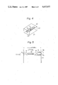
FIG. 4 is a perspective view explaining the semiconductor laser in the device of FIG. 3;
FIG. 5 is a schematic diagram showing an example of a practical constitution of the laser light source device of FIG. 3; and
FIGS. 6 and 7 show plan views of the constitutions of the laser diodes used as modifications in the embodiment of the present invention.
DESCRIPTION OF THE PREFERRED EMBODIMENTS
An embodiment of the present invention will now be explained with reference to the drawings.
FIG. 2 is a diagram explaining an operational principle of portions of the fundamental constitution. A laser 2 has an external resonator including reflection planes (reflection mirrors) 3 and 4, and a Faraday rotator 5 is provided at the laser 2 side front of one of the reflection planes (reflection plane 4 in the figure).
In the oscillational light of a gas laser and the like, two kinds of polarization modes exist in a degenerate state. In the above constitution, clockwise and counter-clockwise circular polarization are adopted and these are made to resonate through the Faraday rotator 5. The Faraday rotator 5 has a different refractive index for the clockwise and counter-clockwise circular polarization, respectively, under a magnetic fields. Since the relationship between the refractive index (n) of a medium and light velocity (v) through the medium is nv=constant, when the clockwise circular polarization and the counter-clockwise circular polarization pass through the Faraday rotator 5 having a predetermined thickness, a difference occurs in the time of the passage of the two polarizations. As a result, the apparent distance between the reflection planes 3 and 4 for the respective polarizations becomes different. Namely, the oscillation frequencies in the clockwise and the counter-clockwise polarizations is different. In the above relationship, if the Faraday rotator 5 is not provided, or if the Faraday rotator 5 is provided but a magnetic field is not applied, the clockwise and the counter-clockwise circular polarizations are in a time reversal relationship with each other. Namely, at that frequency, they are in a degenerate state. At this time, the magnetic field is applied and the degenerate state is released, and one frequency becomes two frequencies.
As mentioned above, the lights each having different frequencies ω+Δω and ω-Δω are output through the reflection plane 4. In the above example, since the two lights passing through the reflection plane 4 are circular polarizations, the polarizations can be separated and be taken out by passing them through a quarter-wave plate and a polarization separating element not shown). By the same processing, the above two lights can be taken out from the reflection plane 3.
The use of the above-mentioned laser is not limited to the gas laser, any arbitrary laser including lights having a circular polarization mode as an oscillatory light can also be used.
On the other hand, when a laser which generates linear polarizations having oscillational directions crossing each other perpendicularly is used, as shown in FIG. 3, quarter- wave plates 6 and 7, as elements through which light is emitted and returned in such a manner that the polarization plane is rotated by 90 degrees, are provided one by one at the laser side fronts of the reflection plane 3 and the Faraday rotator 5. Below, an example of the device shown in FIG. 3 using a semiconductor laser is explained.
In the usual semiconductor laser, two linear polarizations crossing each other perpendicularly are called the TE-wave and the TM-wave, and are an eigen-mode of the resonator. In a semiconductor laser 21 as shown in FIG. 4, the polarization plane of the TE-wave is in parallel with and the TM-wave is perpendicular to an active layer 22 plane (hatched plane) which is the light emitting and waveguide domain. The following is an explanation of the case wherein the above-mentioned TE-wave and TM-wave are irradiated from the end planes 23 and 24 of the semiconductor laser 21 and pass through the quarter- wave plates 6 and 7.
In FIG. 3, the TM-wave irradiated from the end plane 23 of the semiconductor laser 21 is given a circular polarization by the quarter-wave plate 6. This circular polarization is reflected by the reflection plane 3, and then is passed back through the quarter-wave plate 6, to again become a linear polarization. At this time, since the polarization plane is rotated by π/2, the wave was a TE-wave. Further, the light is irradiated from the end plane 24 and passes through the quarter-wave plate 7, and is then again given a circular polarization. This circular polarization is reflected by the reflection plane 4, is passed back through the quarter-wave plate 7, and is then returned as the TM-wave by the rotation of the polarization plane by π/2.
Meanwhile, the TE-wave irradiated from the end plane 23 of the semiconductor laser 21 is given a circular polarization in a reverse direction to that of the above case through the quarter-wave plate 6, and after the TE-wave is reflected by the reflection plane 3, the TE-wave is converted to the TM-wave through the quarter-wave plate 6. Further, the wave is irradiated from the end plane 24, is given a circular polarization in the reverse direction through the quarter-wave plate 7, is reflected by the reflection plane 4, and is then passed through the quarter-wave plate 7 and returned as the TE-wave.
The decision of whether the clockwise or the counter-clockwise circular polarization is given to the respective TE-wave and TM-wave is determined by the positive or negative sign of the angle of ±45 degree which is formed by the axis of the quarter-wave plate and the active layer plane.
As mentioned above, when the Faraday rotator is not provided, or the Faraday rotator is provided but the magnetic field is not applied, the oscillation light of the semiconductor laser 21 resonates in the degenerate state of the TE-wave and TM-wave between the reflection planes 3 and 4. However, even when the quarter- wave plates 6 and 7 are provided at both sides of the semiconductor laser 21, it is impossible to distinguish between the TE-mode and TM-mode.
However, in the lights passing through the Faraday rotator 5, two states having different modes, i.e., clockwise circular polarization and counter-clockwise circular polarization, exist. As mentioned above, since the Faraday rotator 5 has different refractive indexes for the clockwise and the counter-clockwise circular polarization, respectively, the effective distances between the reflection planes 3 and 4 for the two lights having two states are different. Therefore, these lights have different resonant frequencies.
As mentioned above, if the Faraday rotator is not provided, or the Faraday rotator is provided but the magnetic field is not applied thereto, these two modes are in the state of time reversal. Therefore, if the magnetic field is applied and the degeneracy is released, when the frequency of the clockwise circular polarization is given by ω+Δω, the frequency of the counter-clockwise circular polarization is given by ω-Δω.
In the above processing, for example, since the two lights having frequencies of ω+Δω and ω-Δω as clockwise and counter-clockwise circular polarization are emitted from the reflection plane 4, these two lights can be taken out separately by using the quarter-wave plate and polarization separating element as mentioned previously. Namely, in the above constitution, the semiconductor laser can be used as a light source in a manner equivalent to that of a gas laser. Although this semiconductor laser does not need a reflection coating at the end planes 23 and 24, as do the usual semiconductor lasers, it is better to apply the coating to prevent reflection.
The Faraday rotator 5, for example, comprises a magnetic thin plate 5a made of yttrium-iron-garnet (YIG), performs with the characteristic Faraday effect, and is light transmissible, and a ring magnet 5b for magnetizing the magnetic thin plate 5a along the light transmitting direction φ1 or φ2. The magnetic thin plate 5a is mounted in the ring of the ring magnet 5b.
According to the above described embodiment, since the magnetic field to be applied to the Faraday rotator to obtain a required frequency difference (Δω) can be comparatively weak, the construction of the light source device can be made smaller and the control for the frequency difference made easier. In addition, the advantage is gained of obtaining two lights having a constant intensity. Where the frequency difference Δω is fixed to a certain value, a permanent magnet can be used to supply the magnetic field. If an alternating magnetic field is applied, the frequency difference Δω can be modulated.
FIG. 5 shows an example of a practical constitution of a laser light source device according to the embodiment of the present invention. In the figure, a semiconductor laser is used as a light source. The semiconductor laser 21 is put on a heat sink 8, and, for example, spherical condenser lenses 9 and 10 are provided at both the light output ends of the semiconductor laser 21. Quarter- wave plates 61 and 71 are provided at both sides of the spherical lenses 9 and 10, respectively. One side of the quarter-wave plate 61 is coated with a reflection coating 31 having, for example, a reflectivity of 99 percent, and the Faraday rotator 5 is provided adjacent to one side of the quarter-wave plate 71. One side of the Faraday rotator 5 is coated with a reflection coating 41 having, for example, a reflectivity of 90 percent.
The distance between the reflection coatings 31 and 41 is approximately 1 mm, the length between the end planes of the semiconductor laser 21 is approximately 0.3 mm, and the diameter of the spherical lenses 9 and 10 is approximately 0.2 mm. Thus the device is miniaturized and the two-frequencies-supplying laser light source device is obtained. The quarter-wave plate is usually made of a quartz plate having double refraction characteristics.
Each element (2, 3, 4, 5, 6, 7) shown in FIGS. 2 and 3, is practically arranged on stems (not shown) made of non-magnetic metal, e.g., a stainless steel, using a holder for fixing, and a cap (not shown) made of non-magnetic metal is attached to the stems to cover the elements, thus completing the casing of the elements.
FIGS. 6 and 7 show modifications of the present embodiment. In the modifications, the sectional area of the waveguide layer provided adjacent to the active layer of the semiconductor laser 21 is enlarged near the end planes 23 and 24 of the semiconductor laser 21 for receiving and sending the light. These areas are shown as reference numerals 13 and 14 in the plan views of FIG. 6 and FIG. 7, respectively. These modifications prevent the reflection of the laser light at the end planes, and thus an external resonator type semiconductor laser light source device, wherein the complex mode rarely occurs and stable oscillation is performed, is obtained.
As another example of the modification of the present invention, the quarter- wave plates 6 and 7 used as the elements in the device of FIG. 3 can be replaced by a 45 degree Faraday rotator made of yttrium-iron-garnet (YIG), through which the polarization plane is rotated by 90 degrees for each light emission and return. Since the quarter-wave plate has double refraction characteristics, integration of the device is difficult. However, if the Faraday rotator is used instead of the quarter-wave plate, integration of the device can be accomplished.
As yet another example of the modifications, the sectional form of the waveguide layer of the semiconductor laser may have anisotropic characteristics. Namely, if the refractive index of the TE-wave is made to be different from that of the TM-wave, the interaction of the two waves becomes weaker, and thus a stable oscillation can be obtained.
The Faraday rotator 5 having a polarization angle regarding the frequency Δω in the present embodiment, for example, can be made of a paramagnetic glass.
According to the device of the present embodiment, the method of heterodyne measurement on light can be applied over a wide field. For example, if a magnetic field to be measured is applied to the Faraday rotator 5, the device operates as a light frequency modulator, and by utilizing the modulated data, a heterodyne type magnetic field measuring device is obtained.

Claims (10)

We claim:
1. A laser light source device comprising:
a laser having a first end plane and a second end plane, and an external resonator including first and second reflection planes spaced, respectively, from said first and second end planes;
a Faraday rotator positioned between said first end plane and said first reflection plane; and
means associated with said Faraday rotator for producing a magnetic field therein, said magnetic field causing an effect such that light of clockwise circular polarization and light of counter-clockwise circular polarization will be differently affected upon passage through said Faraday rotator, thereby producing from said laser light source device two light outputs, one of each polarization and having different oscillation frequencies determined by the strength of said magnetic field applied to said Faraday rotator.
2. A laser light source device as set forth in claim 1, wherein said Faraday rotator is a 45 degree Faraday rotator.
3. A laser light source device as set forth in claim 2, wherein said 45 degree Faraday rotator is made of yttrium-iron-garnet.
4. A laser light source device as set forth in claim 1, wherein said Faraday rotator is made of a paramagnetic glass.
5. A laser light source device as set forth in claim 1, wherein the eigen-mode of said laser is linear polarizations crossing each other perpendicularly in the oscillating direction thereof, and
said laser device further comprises a pair of elements for rotating a polarization by 90 degrees by one emission-and-return through an element,
said elements being arranged with a first element positioned between said first end plane and said Faraday rotator and a second element positioned between said second end plane and said second reflection plane.
6. A laser light source device as set forth in claim 5, wherein each said element is a quarter-wave plate.
7. A laser light source device as set forth in claim 1, wherein said quarter-wave plate is made of a quartz plate.
8. A laser light source device as set forth in claim 5 wherein said laser is a semiconductor laser including a waveguide, and wherein the sectional area of a waveguide layer adjoined to an active layer of the semiconductor laser is enlarged near the end planes through which the laser light enters and is emitted.
9. A laser light source device as set forth in claim 5 wherein said laser is a semiconductor laser including a waveguide, and wherein a waveguide layer adjoined to an active layer of the semiconductor laser has anisotropic characteristics due to the sectional form thereof so that the refractive index of the transverse electric wave is different from that of the transverse magnetic wave.
10. A laser light source device as set forth in claim 1 or 5, wherein said means for producing a magnetic field produces a magnetic field of variable intensity, and the frequency difference between the different oscillation frequencies of said two light outputs varies in accordance with the intensity of said magnetic field.
US06/654,628 1983-09-26 1984-09-26 Laser light source device Expired - Fee Related US4637027A (en)

Applications Claiming Priority (4)

Application Number Priority Date Filing Date Title
JP58-177227 1983-09-26
JP17723383A JPS6068684A (en) 1983-09-26 1983-09-26 Laser light source
JP17722783A JPH0249667B2 (en) 1983-09-26 1983-09-26 JIKIKOGAKUSOCHI
JP58-177233 1983-09-26

Publications (1)

Publication Number Publication Date
US4637027A true US4637027A (en) 1987-01-13

Family

ID=26497847

Family Applications (1)

Application Number Title Priority Date Filing Date
US06/654,628 Expired - Fee Related US4637027A (en) 1983-09-26 1984-09-26 Laser light source device

Country Status (5)

Country Link
US (1) US4637027A (en)
EP (1) EP0138452B1 (en)
KR (1) KR890003390B1 (en)
CA (1) CA1251846A (en)
DE (1) DE3483766D1 (en)

Cited By (22)

* Cited by examiner, † Cited by third party
Publication number Priority date Publication date Assignee Title
US4794605A (en) * 1986-03-13 1988-12-27 Trw Inc. Method and apparatus for control of phase conjugation cells
US4941738A (en) * 1988-07-29 1990-07-17 American Telephone And Telegraph Company Polarization independent optical amplifier apparatus
US4955006A (en) * 1988-01-13 1990-09-04 Fujitsu Limited Floating type magneto-optic disk reading head system having external semiconductor laser resonator operating at orthogonal two mode oscillations
US4975918A (en) * 1989-06-07 1990-12-04 Maxwell Laboratories, Inc. Tunable laser
US5007060A (en) * 1989-08-01 1991-04-09 Litton Systems, Inc. Linear laser with two-swept frequencies of controlled splitting
US5015070A (en) * 1989-03-14 1991-05-14 Mouse Systems Corporation Reference grid for optical scanner
US5022034A (en) * 1989-06-27 1991-06-04 May A D Laser device, including control of polarization mode
US5091912A (en) * 1990-02-13 1992-02-25 Societe D'applications Generales D'electricite Et De Mecanique Sagem Laser having two modes at different frequencies
US5132978A (en) * 1988-03-02 1992-07-21 British Telecommunications Public Limited Company Laser amplifier
WO1993026066A1 (en) * 1992-06-15 1993-12-23 Cygnus Laser Corporation Nonlinear optical frequency converter
US5355381A (en) * 1992-12-03 1994-10-11 Amoco Corporation Self-heterodyne optical fiber communications system
US5465154A (en) * 1989-05-05 1995-11-07 Levy; Karl B. Optical monitoring of growth and etch rate of materials
US5812304A (en) * 1995-08-29 1998-09-22 Fujitsu Limited Faraday rotator which generates a uniform magnetic field in a magnetic optical element
US5844710A (en) * 1996-09-18 1998-12-01 Fujitsu Limited Faraday rotator and optical device employing the same
US5867300A (en) * 1996-03-01 1999-02-02 Fujitsu Limited Variable optical attenuator which applies a magnetic field to a faraday element to rotate the polarization of a light signal
US5889609A (en) * 1992-07-31 1999-03-30 Fujitsu Limited Optical attenuator
US6018411A (en) * 1996-11-29 2000-01-25 Fujitsu Limited Optical device utilizing magneto-optical effect
US6212209B1 (en) * 1998-03-16 2001-04-03 Lucent Technologies, Inc. Switchable laser using a faraday rotator
US6441955B1 (en) 1998-02-27 2002-08-27 Fujitsu Limited Light wavelength-multiplexing systems
US20020154672A1 (en) * 1999-09-15 2002-10-24 Yeda Research And Development Co. Ltd. Optical resonators with orthogonally polarized modes
US6496300B2 (en) 1998-02-27 2002-12-17 Fujitsu Limited Optical amplifier
US6813286B1 (en) 1997-05-01 2004-11-02 Yeda Research And Development Co. Ltd. Optical resonators with discontinuous phase elements

Families Citing this family (6)

* Cited by examiner, † Cited by third party
Publication number Priority date Publication date Assignee Title
US4944592A (en) * 1987-10-16 1990-07-31 The University Of Texas System Device and method for quantum nondemolition measurements using parametric oscillation
EP0312296A3 (en) * 1987-10-16 1990-04-11 Board Of Regents, The University Of Texas System Device and method for quantum nondemolition measurements using parametric oscillation
FR2682769B1 (en) * 1991-10-17 1995-08-11 Sagem LASER MAGNETOMETER.
JP3167189B2 (en) * 1992-08-31 2001-05-21 浜松ホトニクス株式会社 Voltage measuring device
FR2915631B1 (en) * 2007-04-27 2009-07-10 Thales Sa COMPACT LASER SOURCE WITH LOW SPECTRAL WIDTH.
KR100815483B1 (en) * 2007-05-09 2008-03-20 한국전기연구원 Diode pumped laser apparatus using anisotropic laser crystal

Citations (5)

* Cited by examiner, † Cited by third party
Publication number Priority date Publication date Assignee Title
US3356438A (en) * 1963-06-12 1967-12-05 Sperry Rand Corp Light modulator employing multiplereflective light path
US3436677A (en) * 1964-06-29 1969-04-01 Ibm Magneto-optic radiation control and modulator
US3639855A (en) * 1969-12-19 1972-02-01 Bell Telephone Labor Inc Laser devices
US4305046A (en) * 1978-07-12 1981-12-08 Agence Nationale De La Valorisation De La Recherche (Anvar) Selective optical resonator
US4496518A (en) * 1980-02-27 1985-01-29 Marie G R P TMO and TEO cavity resonator for projecting plasma confining TEO mode components

Family Cites Families (1)

* Cited by examiner, † Cited by third party
Publication number Priority date Publication date Assignee Title
US4222668A (en) * 1978-02-23 1980-09-16 Rockwell International Corporation Ferrimagnetic Faraday elements for ring lasers

Patent Citations (5)

* Cited by examiner, † Cited by third party
Publication number Priority date Publication date Assignee Title
US3356438A (en) * 1963-06-12 1967-12-05 Sperry Rand Corp Light modulator employing multiplereflective light path
US3436677A (en) * 1964-06-29 1969-04-01 Ibm Magneto-optic radiation control and modulator
US3639855A (en) * 1969-12-19 1972-02-01 Bell Telephone Labor Inc Laser devices
US4305046A (en) * 1978-07-12 1981-12-08 Agence Nationale De La Valorisation De La Recherche (Anvar) Selective optical resonator
US4496518A (en) * 1980-02-27 1985-01-29 Marie G R P TMO and TEO cavity resonator for projecting plasma confining TEO mode components

Cited By (32)

* Cited by examiner, † Cited by third party
Publication number Priority date Publication date Assignee Title
US4794605A (en) * 1986-03-13 1988-12-27 Trw Inc. Method and apparatus for control of phase conjugation cells
US4955006A (en) * 1988-01-13 1990-09-04 Fujitsu Limited Floating type magneto-optic disk reading head system having external semiconductor laser resonator operating at orthogonal two mode oscillations
US5132978A (en) * 1988-03-02 1992-07-21 British Telecommunications Public Limited Company Laser amplifier
US4941738A (en) * 1988-07-29 1990-07-17 American Telephone And Telegraph Company Polarization independent optical amplifier apparatus
US5015070A (en) * 1989-03-14 1991-05-14 Mouse Systems Corporation Reference grid for optical scanner
US5465154A (en) * 1989-05-05 1995-11-07 Levy; Karl B. Optical monitoring of growth and etch rate of materials
US4975918A (en) * 1989-06-07 1990-12-04 Maxwell Laboratories, Inc. Tunable laser
US5022034A (en) * 1989-06-27 1991-06-04 May A D Laser device, including control of polarization mode
US5007060A (en) * 1989-08-01 1991-04-09 Litton Systems, Inc. Linear laser with two-swept frequencies of controlled splitting
US5091912A (en) * 1990-02-13 1992-02-25 Societe D'applications Generales D'electricite Et De Mecanique Sagem Laser having two modes at different frequencies
WO1993026066A1 (en) * 1992-06-15 1993-12-23 Cygnus Laser Corporation Nonlinear optical frequency converter
US6275323B1 (en) 1992-07-31 2001-08-14 Fujitsu Limited Optical attenuator
US6018412A (en) * 1992-07-31 2000-01-25 Fujitsu Limited Optical attenuator
US5889609A (en) * 1992-07-31 1999-03-30 Fujitsu Limited Optical attenuator
US5355381A (en) * 1992-12-03 1994-10-11 Amoco Corporation Self-heterodyne optical fiber communications system
US5812304A (en) * 1995-08-29 1998-09-22 Fujitsu Limited Faraday rotator which generates a uniform magnetic field in a magnetic optical element
US5973821A (en) * 1996-03-01 1999-10-26 Fujitsu Limited Variable optical attenuator which applies a magnetic field to a faraday element to rotate the polarization of light signal
US6570699B2 (en) 1996-03-01 2003-05-27 Fujitsu Limited Variable optical attenuator which applies a magnetic field to a Faraday element to rotate the polarization of a light signal
US6717713B2 (en) 1996-03-01 2004-04-06 Fujitsu Limited Variable optical attenuator which applies a magnetic field to a faraday element to rotate the polarization of a light signal
US20030210451A1 (en) * 1996-03-01 2003-11-13 Fujitsu Limited Variable optical attenuator which applies a magnetic field to a faraday element to rotate the polarization of a light signal
US5867300A (en) * 1996-03-01 1999-02-02 Fujitsu Limited Variable optical attenuator which applies a magnetic field to a faraday element to rotate the polarization of a light signal
US6333806B1 (en) 1996-03-01 2001-12-25 Fujitsu Limited Variable optical attenuator which applies a magnetic field to a Faraday element to rotate the polarization of a light signal
US5844710A (en) * 1996-09-18 1998-12-01 Fujitsu Limited Faraday rotator and optical device employing the same
US6018411A (en) * 1996-11-29 2000-01-25 Fujitsu Limited Optical device utilizing magneto-optical effect
US6813286B1 (en) 1997-05-01 2004-11-02 Yeda Research And Development Co. Ltd. Optical resonators with discontinuous phase elements
US6496300B2 (en) 1998-02-27 2002-12-17 Fujitsu Limited Optical amplifier
US20030025965A1 (en) * 1998-02-27 2003-02-06 Fujitsu Limited Light wavelength-multiplexing systems
US6441955B1 (en) 1998-02-27 2002-08-27 Fujitsu Limited Light wavelength-multiplexing systems
US6919987B2 (en) 1998-02-27 2005-07-19 Fujitsu Limited Light wavelength-multiplexing systems
US6212209B1 (en) * 1998-03-16 2001-04-03 Lucent Technologies, Inc. Switchable laser using a faraday rotator
US20020154672A1 (en) * 1999-09-15 2002-10-24 Yeda Research And Development Co. Ltd. Optical resonators with orthogonally polarized modes
US6850544B2 (en) * 1999-09-15 2005-02-01 Yeda Research And Development Co., Ltd. Optical resonators with orthogonally polarized modes

Also Published As

Publication number Publication date
KR850002611A (en) 1985-05-15
EP0138452A2 (en) 1985-04-24
DE3483766D1 (en) 1991-01-31
KR890003390B1 (en) 1989-09-19
CA1251846A (en) 1989-03-28
EP0138452B1 (en) 1990-12-19
EP0138452A3 (en) 1987-04-29

Similar Documents

Publication Publication Date Title
US4637027A (en) Laser light source device
CA1304970C (en) Polarization maintaining fiber interferometer and method for source stabilization
US4890922A (en) Thermally compensated reference interferometer and method
US4274742A (en) Passive ring laser rate of turn devices
JPH05129700A (en) Laser system and method of converting frequency
US5617435A (en) Lasing system with wavelength-conversion waveguide
JPH02119280A (en) Laser resonator
JP2501302B2 (en) LASER DEVICE AND METHOD
KR910006660B1 (en) Fixed magneto-optic head system
US7551342B2 (en) Optical frequency comb generator and optical modulator
JPS63279115A (en) Measuring device with laser and annular resonator
US3418476A (en) Device for internal modulation of laser radiation
US3752586A (en) Minimizing frequency locking in ring laser gyroscopes
US4765740A (en) Optical apparatus based on measurement of phase or frequency shift of an oscillating beam, particularly useful as an optical gyro
Kravtsov et al. Nonlinear dynamics of solid-state ring lasers
US3486130A (en) Ring laser having a quarter wave plate for rotating the plane of polarization of light which is reflected back into the ring from the combining optics
US3500233A (en) Frequency modulated laser device
JP3428067B2 (en) Displacement measuring method and displacement measuring device used therefor
Boon-Engering et al. Stabilization of an optical cavity containing a birefringent element
US3941481A (en) Ring laser having elastic wave bias
JPH0136986B2 (en)
CN114370928B (en) Linear type Sagnac interference type optical fiber vibration sensor
US5737080A (en) Solid state nonplanar laser gyroscope
US6462857B2 (en) Optical modulator and optical modulation method
Porte et al. Band pass & low-voltage symmetrical electro-optic modulator for absolute distance metrology

Legal Events

Date Code Title Description
AS Assignment

Owner name: FUJITSU LIMITED, 1015, KAMIKODANAKA, NAKAHARA-KU,

Free format text: ASSIGNMENT OF ASSIGNORS INTEREST.;ASSIGNORS:SHIRASAKI, MASATAKA;NAKAJIMA, HIROCHIKA;FURUKAWA, YASUO;AND OTHERS;REEL/FRAME:004318/0958

Effective date: 19840905

FEPP Fee payment procedure

Free format text: PAYOR NUMBER ASSIGNED (ORIGINAL EVENT CODE: ASPN); ENTITY STATUS OF PATENT OWNER: LARGE ENTITY

FPAY Fee payment

Year of fee payment: 4

REMI Maintenance fee reminder mailed
LAPS Lapse for failure to pay maintenance fees
FP Lapsed due to failure to pay maintenance fee

Effective date: 19990113

STCH Information on status: patent discontinuation

Free format text: PATENT EXPIRED DUE TO NONPAYMENT OF MAINTENANCE FEES UNDER 37 CFR 1.362