US4646815A - Heat exchange mat - Google Patents

Heat exchange mat Download PDF

Info

Publication number
US4646815A
US4646815A US06/682,177 US68217784A US4646815A US 4646815 A US4646815 A US 4646815A US 68217784 A US68217784 A US 68217784A US 4646815 A US4646815 A US 4646815A
Authority
US
United States
Prior art keywords
mat
heat exchange
members
fluid
pair
Prior art date
Legal status (The legal status is an assumption and is not a legal conclusion. Google has not performed a legal analysis and makes no representation as to the accuracy of the status listed.)
Expired - Fee Related
Application number
US06/682,177
Inventor
Hideo Iwata
Yoshiaki Kitagawa
Jiro Koshijima
Tetsuya Tachibana
Current Assignee (The listed assignees may be inaccurate. Google has not performed a legal analysis and makes no representation or warranty as to the accuracy of the list.)
Panasonic Holdings Corp
Original Assignee
Matsushita Electric Works Ltd
Priority date (The priority date is an assumption and is not a legal conclusion. Google has not performed a legal analysis and makes no representation as to the accuracy of the date listed.)
Filing date
Publication date
Priority claimed from JP58250767A external-priority patent/JPS60134194A/en
Priority claimed from JP902584A external-priority patent/JPS60152894A/en
Priority claimed from JP59098403A external-priority patent/JPS60240933A/en
Application filed by Matsushita Electric Works Ltd filed Critical Matsushita Electric Works Ltd
Assigned to MATSUSHITA ELECTRIC WORKS, LTD. reassignment MATSUSHITA ELECTRIC WORKS, LTD. ASSIGNMENT OF ASSIGNORS INTEREST. Assignors: IWATA, HIDEO, KITAGAWA, YOSHIAKI, KOSHIJIMA, JIRO, TACHIBANA, TETSUYA
Application granted granted Critical
Publication of US4646815A publication Critical patent/US4646815A/en
Anticipated expiration legal-status Critical
Expired - Fee Related legal-status Critical Current

Links

Images

Classifications

    • FMECHANICAL ENGINEERING; LIGHTING; HEATING; WEAPONS; BLASTING
    • F28HEAT EXCHANGE IN GENERAL
    • F28DHEAT-EXCHANGE APPARATUS, NOT PROVIDED FOR IN ANOTHER SUBCLASS, IN WHICH THE HEAT-EXCHANGE MEDIA DO NOT COME INTO DIRECT CONTACT
    • F28D1/00Heat-exchange apparatus having stationary conduit assemblies for one heat-exchange medium only, the media being in contact with different sides of the conduit wall, in which the other heat-exchange medium is a large body of fluid, e.g. domestic or motor car radiators
    • F28D1/02Heat-exchange apparatus having stationary conduit assemblies for one heat-exchange medium only, the media being in contact with different sides of the conduit wall, in which the other heat-exchange medium is a large body of fluid, e.g. domestic or motor car radiators with heat-exchange conduits immersed in the body of fluid
    • F28D1/03Heat-exchange apparatus having stationary conduit assemblies for one heat-exchange medium only, the media being in contact with different sides of the conduit wall, in which the other heat-exchange medium is a large body of fluid, e.g. domestic or motor car radiators with heat-exchange conduits immersed in the body of fluid with plate-like or laminated conduits
    • F28D1/0308Heat-exchange apparatus having stationary conduit assemblies for one heat-exchange medium only, the media being in contact with different sides of the conduit wall, in which the other heat-exchange medium is a large body of fluid, e.g. domestic or motor car radiators with heat-exchange conduits immersed in the body of fluid with plate-like or laminated conduits the conduits being formed by paired plates touching each other
    • FMECHANICAL ENGINEERING; LIGHTING; HEATING; WEAPONS; BLASTING
    • F24HEATING; RANGES; VENTILATING
    • F24DDOMESTIC- OR SPACE-HEATING SYSTEMS, e.g. CENTRAL HEATING SYSTEMS; DOMESTIC HOT-WATER SUPPLY SYSTEMS; ELEMENTS OR COMPONENTS THEREFOR
    • F24D3/00Hot-water central heating systems
    • F24D3/12Tube and panel arrangements for ceiling, wall, or underfloor heating
    • F24D3/122Details
    • F24D3/125Hydraulic pipe connections
    • FMECHANICAL ENGINEERING; LIGHTING; HEATING; WEAPONS; BLASTING
    • F24HEATING; RANGES; VENTILATING
    • F24DDOMESTIC- OR SPACE-HEATING SYSTEMS, e.g. CENTRAL HEATING SYSTEMS; DOMESTIC HOT-WATER SUPPLY SYSTEMS; ELEMENTS OR COMPONENTS THEREFOR
    • F24D3/00Hot-water central heating systems
    • F24D3/12Tube and panel arrangements for ceiling, wall, or underfloor heating
    • F24D3/122Details
    • F24D3/127Mechanical connections between panels
    • FMECHANICAL ENGINEERING; LIGHTING; HEATING; WEAPONS; BLASTING
    • F28HEAT EXCHANGE IN GENERAL
    • F28FDETAILS OF HEAT-EXCHANGE AND HEAT-TRANSFER APPARATUS, OF GENERAL APPLICATION
    • F28F3/00Plate-like or laminated elements; Assemblies of plate-like or laminated elements
    • F28F3/12Elements constructed in the shape of a hollow panel, e.g. with channels
    • YGENERAL TAGGING OF NEW TECHNOLOGICAL DEVELOPMENTS; GENERAL TAGGING OF CROSS-SECTIONAL TECHNOLOGIES SPANNING OVER SEVERAL SECTIONS OF THE IPC; TECHNICAL SUBJECTS COVERED BY FORMER USPC CROSS-REFERENCE ART COLLECTIONS [XRACs] AND DIGESTS
    • Y02TECHNOLOGIES OR APPLICATIONS FOR MITIGATION OR ADAPTATION AGAINST CLIMATE CHANGE
    • Y02BCLIMATE CHANGE MITIGATION TECHNOLOGIES RELATED TO BUILDINGS, e.g. HOUSING, HOUSE APPLIANCES OR RELATED END-USER APPLICATIONS
    • Y02B30/00Energy efficient heating, ventilation or air conditioning [HVAC]

Definitions

  • This invention relates to mat-shaped heat exchangers employing such heat exchanging fluid as hot water caused to flow therethrough and, more specifically, to a heat exchange mat formed into a flat sheet shape for laying on a floor so as to achieve, for example, floor surface heating with hot water circulated throughout the interior of the mat.
  • the heat exchange mat comprises, as shown in FIG. 1, a heat exchanging element 1 of wavy warp and linear weft filaments 2 and 3 of a metal or plastic material and knitted with each other substantially perpendicularly, and a face sheet 5 made of a polyvinyl chloride or the like and bonded to each of top and bottom faces of the element 1 with such an insert 4 as a textile material interposed between them.
  • a primary object of the present invention is, therefore, to provide a heat exchange mat which eliminates such problems as in the known devices, preventing specifically any deformation of the mat at any side edge thereof so as to attain the overall flatness of the mat suitable for lying on the room floor.
  • This object of the invention can be attained by linking at least a pair of heat exchange mat members together at their one side edge apt to be bent upward upon application of the roll pressing force and opposed to each other, with a link member acting as a partition while allowing the interior of the both mat members to communicate with each other at least at one end part of the link member.
  • Another important object of the present invention is to provide a heat exchange mat which attains the overall flatness even at the heat-exchanging-fluid supply and discharge means for the pair of heat exchange mat members, minimizing any level difference all over the mat. According to another feature of the present invention, therefore, this object is attained by employing a sufficiently flattened supply and discharge means for the heat exchange fluid to be circulated through the pair of mat members, as provided at the other end of the link member.
  • Sitll another object of the present invention is to provide a heat exchange mat in which the heat exchanging fluid can smoothly flow between the pair of mat members.
  • FIG. 1 is a fragmental perspective view with certain parts removed for showing interior structure of a heat exchange mat to which the present invention relates;
  • FIG. 2 is a schematic cross sectional view of the heat exchange mat of FIG. 1;
  • FIG. 3 is a schematic cross sectional view of a mat comprising a pair of heat exchange mat members as linked according to the present invention, in a state before being used;
  • FIG. 4 is a similar schematic cross sectional view of the mat of FIG. 3 but in a state of being used;
  • FIG. 5 is a top plan view of the mat of FIG. 3;
  • FIGS. 6 through 10 are perspective views of different embodiments of the mat according to the present invention, wherein the heat exchange fluid can flow from one of the pair of heat exchange members of the mat to the other at one end part of a link member between them, and means for supplying and discharging the fluid to and from the mat is provided at the other end part of the link means;
  • FIG. 11 is a perspective view of another embodiment of the mat according to the present invention employing a different link member for the pair of heat exchange mat members which are shown as separated from each other;
  • FIG. 12 is a fragmental perspective view at the fluid supply and discharge means of the mat in still another embodiment of the present invention having a featured arrangement for mounting the means to the mat;
  • FIGS. 13 and 14 are fragmentary perspective views respectively of the mat members in a further embodiment of the present invention at a part where the fluid supply and discharge means is to be mounted, and of the means before being mounted;
  • FIG. 15 is a fragmentary perspective view of the mat members and fluid supply and discharge means as mounted thereto in the embodiments of FIGS. 13 and 14.
  • a heat exchange mat 10 comprises, as a remarkable feature of the present invention, a pair of mat members 11a and 11b respectively formed in the manner disclosed with reference to FIG. 1.
  • the members are arranged side by side as opposed at one of their side edges where the linear weft filaments 3 terminate and specifically where each mat member tends to bend upward as has been explained with reference to FIG. 2.
  • These mat members are integrally linked to each other in fluid tight manner by means of a link member 12 of such a plastic material as polyvinyl chloride or the like which is H-shaped in section and extending along the side edge of the mat member.
  • a peripheral sealing member 13 also of such a plastic material as polyvinyl chloride or the like is adhered in fluid tight manner to both face sheets 5 along all other peripheral edges of the mat members 11a and 11b.
  • the action of the link member 12 as a partition is utilized for rendering the thermal distribution with the heat exchanging fluid supplied into the heat exchange mat to be uniform.
  • a link member 22 in a heat exchange mat 20 is partly removed at its one end so that the interior of a pair of mat members 21a and 21b will communicate with each other through a passage 24 provided at the removed end of the link member 22.
  • the sheets 5 are suitably bonded at the passage 24.
  • Tubes 25 and 26 for supplying the heat exchanging fluid into the mat member 21a and discharging the fluid out of the other mat member 21b are fluid tightly coupled to these members, respectively in the vicinity of the other end of the link member 22 and close relation to each other.
  • the heat exchanging fluid supplied into the heat exchange mat 20 through the supply tube 25 can be prevented from being immediately discharged out of the mat through the discharge tube 26, by means of the partitioning link member 22 between the closely disposed tubes, so that the fluid will travel throughout the mat member 21a until it reaches the passage 24 and further throughout the other mat member 21b from the passage 24 to the discharge tube 26.
  • the partitioning link member 22 between the closely disposed tubes so that the fluid will travel throughout the mat member 21a until it reaches the passage 24 and further throughout the other mat member 21b from the passage 24 to the discharge tube 26.
  • the means for supplying and discharging the heat exchanging fluid is made to be flat so that, in the case where the mat is laid on a room floor surface, the danger, for example, of false step of the user due to a raised provision of such supply and discharge means can be well removed.
  • the mat may be used with less danger when the supply and discharge tubes 25 and 26 are positioned, for example, at a room corner but the mat will lose the freedom of use in respect of its disposition in the room.
  • a heat exchange mat 30 as shown in FIGS.
  • a link member 32 made similarly to that of the above embodiment for a pair of mat members 31a and 31b is removed or shortened at its both ends.
  • Joint members 37 and 38 made of such plastic material as polyvinyl chloride or the like are secured fluid tightly to the removed ends of the member 32.
  • Fluid supply and discharge pipes 35 and 36 are provided in one of the joint members, i.e., in the joint member 37, so as to extend out of an outer end face coplanar with the mat 30.
  • the pipes are mutually separated within the member 37 by a partitioning wall 39 which extends from the other inner end face abutting the link member 32 to the outer end face, at intermediate point between the supply and discharge tubes 35 and 36, so as to define in the member 37 fluid supply and discharge paths 40 and 41 divided by the wall 39 to respectively communicate between each interior of the mat member 31a or 31b and the supply tube 35 or discharge tube 36.
  • the other joint member 38 is made hollow and secured at the same position as the passage 24 in the embodiment of FIG. 6, so as to form a passage communicating between the both interiors of the mat members 31a and 31b. Is in the case of FIG. 6, the heat exchanging fluid flows in the directions of arrows shown in FIGS.
  • a corresponding joint member 58 in a further embodiment of FIGS. 9 and 10 is provided therein with the same heat exchange element as that which forms a pair of mat members 51a and 51b while defining a communication path 54 between them. More specifically, in a heat exchange mat 50 comprising the pair of mat members 51a and 51b linked by a shortened link member 52, a corner part facing the path 54 of both mat members 51a and 51b is cut off diagonally to form a triangular notch at an end part of the link member 52.
  • Complementarily triangular joint member 58 having therein a heat exchange element 62 also of the complementarily triangular shape is fitted into the triangular notch in fluid tight manner with respect to the face sheets and inserts on both surfaces of the mat members 51a and 51b.
  • Operation of the mat 50 is substantially the same as those in FIG. 1 and the foregoing embodiments. In the present embodiment, therefore, the heat exchanging action can be obtained also at the communication path 54 in addition to that attained by the mat members 51a and 51b, thus, with an improvement to the case of FIG. 6 in this respect.
  • the number of the mat members is not limited only to a pair but any desired number more than that may easily be employed with the same arrangement for forming the heat exchange mat adapted to be laid on a floor.
  • the mat members have been explained to be rectangular in the respective embodiments disclosed, but a pair of mat members each having, for example, a right triangle may be employed as combined into a rectangle as a whole, in which the link member as well as the joint members are disposed to lie on a diagonal of the rectangle, whereby substantially the same heat exchange mat as in the respective embodiments disclosed can be obtained.
  • the heat exchange mats have been explained to be flexible, it will be readily appreciated by those skilled in the art that the face sheet may be of a rigid material if necessary.
  • a movable plate 92 of a U-shaped as viewed from the top is rotatably hinged at both leg ends to raised bosses 93a and 93b provided on both leg ends of also U-shaped stationary plate 91 so that, when the movable plate 92 is rotated to its closed position with respect to the stationary plate 91, both plates 92 and 91 can abut against the top and bottom surfaces of the joint member 37 with or without the fluid supply and discharge tube 35 and 36.
  • the jig 90 is fitted to the joint member prior to the press and removed after the press and cooling of the member and jig, whereby the joint member can be effectively prevented from being thermally deformed or separated from the mat members as fused rather to a heat pressing roller or the like when the joint member is pressed and heated directly.
  • the assembling efficiency of the mat employing the fluid supply and discharge means of such structure as shown in FIGS. 7 and 8 can be made higher.
  • mat members 101a, 101b and their link member 102 are formed to be provided, at their end edge on the fluid supply and discharge side, with notches 113a, 113b and 114 respectively, and a joint member 107 having therein a centrally extended partition 109 is made to have short inward projections 115a and 115b symmetrical with respect to the partition 109, so that the tip end of the partition 109 can fit into the notch 114 and the projections 115a and 115b can fit into the notches 113a and 113b With such an arrangement, when the joint member 107 of FIG.

Abstract

A heat exchange mat comprises at least a pair of mat members respectively including a heat exchange element and arranged side by side with their one side edges opposed, an elongated link member acting as a partition and linking between the opposed side edges of the mat members while allowing the interior of the respective members to communicate with each other at one longitudinal end of the link member, and means for supplying and discharging a heat exchange fluid to one of the mat members and out of the other member through supply and discharge tubes provided close to each other, the means being mounted to the mat at the other end of the link member, whereby substantially uniform thermal distribution overall the heat exchange mat is attained with remarkable improvement in the heat exchanging efficiency at its installing place.

Description

BACKGROUND OF THE INVENTION
This invention relates to mat-shaped heat exchangers employing such heat exchanging fluid as hot water caused to flow therethrough and, more specifically, to a heat exchange mat formed into a flat sheet shape for laying on a floor so as to achieve, for example, floor surface heating with hot water circulated throughout the interior of the mat.
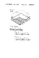
Conventional apparatuses for exchanging heat of a fluid with room air could be disposed only at a corner part of a house room and their heat exchanging efficiency has been insufficient. For this reason, there have been recently developed such flat heat exchange mats that can be laid on a floor or wall surface for exchanging heat with the room air to improve the heat exchanging efficiency. In this case, the heat exchange mat comprises, as shown in FIG. 1, a heat exchanging element 1 of wavy warp and linear weft filaments 2 and 3 of a metal or plastic material and knitted with each other substantially perpendicularly, and a face sheet 5 made of a polyvinyl chloride or the like and bonded to each of top and bottom faces of the element 1 with such an insert 4 as a textile material interposed between them. In firmly bonding the face sheet 5 with the interposed insert 4 to the heat exchanging element 1, usually, a roll pressing force must be applied at least to one of the face sheets 5 so that the force will cause the element 1 to be once compressed to fall down to become smaller in thickness. While the original state of the element 1 can be substantially restored from this compressed state with the restoring force of the filaments specifically when hot water or the like heat exchanging fluid is fed to flow through passages 6 defined between the top and bottom inserts 4, it has been known that the linear weft filaments 3 are caused to be bent downward at their one longitudinal end part and upward at the other end part so that the mat will be wavy at opposing side edges in opposite upward and downward directions as shown in FIG. 2, whereby a problem is caused to arise in that the upward and downward bent edges of the mat laid on the floor give to a user walking on the mat a danger of false step.
On the other hand, there has been suggested in U.S. Pat. No. 4,230,175 a heat exchange mat provided as a flexible sheet adapted to be laid on a flat surface and to be applied to solar water-heater. This mat is provided, however, at both opposing side edges with heat-exchanging-fluid supplying and discharging members which are larger in thickness than the mat itself so that the mat laid on a room floor may also give to the user the same danger of false step at the higher fluid supplying and discharging members. For this reason, too, it has been demanded to provide a heat exchange mat which is evenly flat without any rising part.
DISCLOSURE OF THE INVENTION
A primary object of the present invention is, therefore, to provide a heat exchange mat which eliminates such problems as in the known devices, preventing specifically any deformation of the mat at any side edge thereof so as to attain the overall flatness of the mat suitable for lying on the room floor. This object of the invention can be attained by linking at least a pair of heat exchange mat members together at their one side edge apt to be bent upward upon application of the roll pressing force and opposed to each other, with a link member acting as a partition while allowing the interior of the both mat members to communicate with each other at least at one end part of the link member.
Another important object of the present invention is to provide a heat exchange mat which attains the overall flatness even at the heat-exchanging-fluid supply and discharge means for the pair of heat exchange mat members, minimizing any level difference all over the mat. According to another feature of the present invention, therefore, this object is attained by employing a sufficiently flattened supply and discharge means for the heat exchange fluid to be circulated through the pair of mat members, as provided at the other end of the link member.
Sitll another object of the present invention is to provide a heat exchange mat in which the heat exchanging fluid can smoothly flow between the pair of mat members.
Other objects and advantages of the present invention shall become clear from the following description of the invention detailed with reference to preferred embodiments shown in accompanying drawings.
BRIEF EXPLANATION OF THE DRAWINGS
FIG. 1 is a fragmental perspective view with certain parts removed for showing interior structure of a heat exchange mat to which the present invention relates;
FIG. 2 is a schematic cross sectional view of the heat exchange mat of FIG. 1;
FIG. 3 is a schematic cross sectional view of a mat comprising a pair of heat exchange mat members as linked according to the present invention, in a state before being used;
FIG. 4 is a similar schematic cross sectional view of the mat of FIG. 3 but in a state of being used;
FIG. 5 is a top plan view of the mat of FIG. 3;
FIGS. 6 through 10 are perspective views of different embodiments of the mat according to the present invention, wherein the heat exchange fluid can flow from one of the pair of heat exchange members of the mat to the other at one end part of a link member between them, and means for supplying and discharging the fluid to and from the mat is provided at the other end part of the link means;
FIG. 11 is a perspective view of another embodiment of the mat according to the present invention employing a different link member for the pair of heat exchange mat members which are shown as separated from each other;
FIG. 12 is a fragmental perspective view at the fluid supply and discharge means of the mat in still another embodiment of the present invention having a featured arrangement for mounting the means to the mat;
FIGS. 13 and 14 are fragmentary perspective views respectively of the mat members in a further embodiment of the present invention at a part where the fluid supply and discharge means is to be mounted, and of the means before being mounted; and
FIG. 15 is a fragmentary perspective view of the mat members and fluid supply and discharge means as mounted thereto in the embodiments of FIGS. 13 and 14.
While the present invention shall now be described with reference to the preferred embodiments shown in the drawings, it should be understood that the intention is not to limit the invention only to the particular embodiments shown but rather to cover all alterations, modifications and equivalent arrangements possible within the scope of appended claims.
DISCLOSURE OF PREFERRED EMBODIMENTS
Referring to FIGS. 3 to 5, a heat exchange mat 10 comprises, as a remarkable feature of the present invention, a pair of mat members 11a and 11b respectively formed in the manner disclosed with reference to FIG. 1. The members are arranged side by side as opposed at one of their side edges where the linear weft filaments 3 terminate and specifically where each mat member tends to bend upward as has been explained with reference to FIG. 2. These mat members are integrally linked to each other in fluid tight manner by means of a link member 12 of such a plastic material as polyvinyl chloride or the like which is H-shaped in section and extending along the side edge of the mat member. A peripheral sealing member 13 also of such a plastic material as polyvinyl chloride or the like is adhered in fluid tight manner to both face sheets 5 along all other peripheral edges of the mat members 11a and 11b. With this arrangement, the tendency of both mat members 11a and 11b to bend upwardly at the edges (due to the application of the rolling press force for firmly bonding the heat exchange element 1 with the insert 4 and face sheets 5 as explained earlier) can be effectively suppressed by the link member 12 as shown in FIG. 4. Because the danger of false step of the user mostly arises at an upward bent edge of any mat, the heat exchange mat 10 of this arrangement prevents effectively such danger from occurring even when the mat is laid on a room floor surface.
According to another feature of the present invention, the action of the link member 12 as a partition is utilized for rendering the thermal distribution with the heat exchanging fluid supplied into the heat exchange mat to be uniform. Referring to FIG. 6, a link member 22 in a heat exchange mat 20 is partly removed at its one end so that the interior of a pair of mat members 21a and 21b will communicate with each other through a passage 24 provided at the removed end of the link member 22. The sheets 5 are suitably bonded at the passage 24. Tubes 25 and 26 for supplying the heat exchanging fluid into the mat member 21a and discharging the fluid out of the other mat member 21b are fluid tightly coupled to these members, respectively in the vicinity of the other end of the link member 22 and close relation to each other. With such a structure, the heat exchanging fluid supplied into the heat exchange mat 20 through the supply tube 25 can be prevented from being immediately discharged out of the mat through the discharge tube 26, by means of the partitioning link member 22 between the closely disposed tubes, so that the fluid will travel throughout the mat member 21a until it reaches the passage 24 and further throughout the other mat member 21b from the passage 24 to the discharge tube 26. As a result, such local concentration of heat and uneven thermal distribution that the heat exchange is higher at a part near the supply tube 25 but is lower as the heat exchange fluid leaves the tube 25 can be avoided, and a uniform thermal distribution for substantially uniform heat exchange all over the mat can be realized.
According to still another feature of the present invention, the means for supplying and discharging the heat exchanging fluid is made to be flat so that, in the case where the mat is laid on a room floor surface, the danger, for example, of false step of the user due to a raised provision of such supply and discharge means can be well removed. In the case of the mat of FIG. 6, the mat may be used with less danger when the supply and discharge tubes 25 and 26 are positioned, for example, at a room corner but the mat will lose the freedom of use in respect of its disposition in the room. In order to overcome this, such a heat exchange mat 30 as shown in FIGS. 7 and 8 is suggested, in which a link member 32 made similarly to that of the above embodiment for a pair of mat members 31a and 31b is removed or shortened at its both ends. Joint members 37 and 38 made of such plastic material as polyvinyl chloride or the like are secured fluid tightly to the removed ends of the member 32. Fluid supply and discharge pipes 35 and 36 are provided in one of the joint members, i.e., in the joint member 37, so as to extend out of an outer end face coplanar with the mat 30. The pipes are mutually separated within the member 37 by a partitioning wall 39 which extends from the other inner end face abutting the link member 32 to the outer end face, at intermediate point between the supply and discharge tubes 35 and 36, so as to define in the member 37 fluid supply and discharge paths 40 and 41 divided by the wall 39 to respectively communicate between each interior of the mat member 31a or 31b and the supply tube 35 or discharge tube 36. The other joint member 38 is made hollow and secured at the same position as the passage 24 in the embodiment of FIG. 6, so as to form a passage communicating between the both interiors of the mat members 31a and 31b. Is in the case of FIG. 6, the heat exchanging fluid flows in the directions of arrows shown in FIGS. 7 and 8 so that the uniform thermal distribution of the fluid can be realized, while the freedom of use in the disposition of the mat is well maintained with the fluid supply and discharge means effectively flattened by such provision of the supply and discharge pipes 35 and 36. As the joint members 37 and 38 are mounted to the both shortened ends of the link member 32, the linked end edges of the mat members 31a and 31b can be prevented from causing such upward deformation as has been disclosed, by means of the link and joint members 32, 37 and 38 which are effective to strengthen the mat structure.
While in the above embodiment the joint member 38 is hollow, a corresponding joint member 58 in a further embodiment of FIGS. 9 and 10 is provided therein with the same heat exchange element as that which forms a pair of mat members 51a and 51b while defining a communication path 54 between them. More specifically, in a heat exchange mat 50 comprising the pair of mat members 51a and 51b linked by a shortened link member 52, a corner part facing the path 54 of both mat members 51a and 51b is cut off diagonally to form a triangular notch at an end part of the link member 52. Complementarily triangular joint member 58 having therein a heat exchange element 62 also of the complementarily triangular shape is fitted into the triangular notch in fluid tight manner with respect to the face sheets and inserts on both surfaces of the mat members 51a and 51b. Operation of the mat 50 is substantially the same as those in FIG. 1 and the foregoing embodiments. In the present embodiment, therefore, the heat exchanging action can be obtained also at the communication path 54 in addition to that attained by the mat members 51a and 51b, thus, with an improvement to the case of FIG. 6 in this respect.
In linking the pair of mat members, further, it is preferable to employ the link member of an H-shaped section, but an alternative measure may be taken as shown in FIG. 11, in which opposed side edges of a pair of mat members 81a and 81b showing the tendency of upward deformation are covered respectively with a pair of shortened link bars 82a and 82b of U-shaped section. The bars are bonded together at their opposed side faces, and then joint members similar to those disclosed in connection with FIGS. 7 and 8 are mounted to remainrng open parts between the mat members 81a and 81b at both ends of the bars 82a and 83b, whereby substantially the same effect as that of the foregoing embodiments can be obtained. While not shown, further, the number of the mat members is not limited only to a pair but any desired number more than that may easily be employed with the same arrangement for forming the heat exchange mat adapted to be laid on a floor. In addition, the mat members have been explained to be rectangular in the respective embodiments disclosed, but a pair of mat members each having, for example, a right triangle may be employed as combined into a rectangle as a whole, in which the link member as well as the joint members are disposed to lie on a diagonal of the rectangle, whereby substantially the same heat exchange mat as in the respective embodiments disclosed can be obtained. Furthermore, although the heat exchange mats have been explained to be flexible, it will be readily appreciated by those skilled in the art that the face sheet may be of a rigid material if necessary.
In mounting the respective joint members in the respective embodiments of FIGS. 7 to 10, on the other hand, such a jig 90 as shown in FIG. 12 is preferably used. More specifically, in the illustrated jig 90, a movable plate 92 of a U-shaped as viewed from the top is rotatably hinged at both leg ends to raised bosses 93a and 93b provided on both leg ends of also U-shaped stationary plate 91 so that, when the movable plate 92 is rotated to its closed position with respect to the stationary plate 91, both plates 92 and 91 can abut against the top and bottom surfaces of the joint member 37 with or without the fluid supply and discharge tube 35 and 36. When the mat members linked with the link and joint members are subjected to the heat roll press, therefore, the jig 90 is fitted to the joint member prior to the press and removed after the press and cooling of the member and jig, whereby the joint member can be effectively prevented from being thermally deformed or separated from the mat members as fused rather to a heat pressing roller or the like when the joint member is pressed and heated directly.
According to a further feature of the present invention, the assembling efficiency of the mat employing the fluid supply and discharge means of such structure as shown in FIGS. 7 and 8 can be made higher. Referring to FIGS. 13 to 15, mat members 101a, 101b and their link member 102 are formed to be provided, at their end edge on the fluid supply and discharge side, with notches 113a, 113b and 114 respectively, and a joint member 107 having therein a centrally extended partition 109 is made to have short inward projections 115a and 115b symmetrical with respect to the partition 109, so that the tip end of the partition 109 can fit into the notch 114 and the projections 115a and 115b can fit into the notches 113a and 113b With such an arrangement, when the joint member 107 of FIG. 14 is mounted to the mat members of FIG. 13, the notches 113a, 113b and 114 thus receiving respectively the projections 115a and 115b and tip end of the partition 109 perform a favourable guiding and positioning action so as to provide a high assembability to the mat of the present invention.

Claims (10)

What is claimed as our invention is:
1. A floor heat exchange mat comprising at least a pair of flexible mat members, each mat member including top and bottom face sheets defining an interior space therebetween, a pair of inserts disposed within said interior space, and heat exchanger means disposed between said inserts, said heat exchanger means including wavy warp and linear weft filaments knitted substantially perpendicularly with each other for allowing a heat exchange fluid to flow through the interior space of said mat member, each mat member including a plurality of side edges, one of said side edges at which said weft filaments terminate being inherently upwardly biased relative to remaining portions of said mat member in response to being heated by the heat exchange fluid, said mat members arranged such that said upwardly biased edges lie side-by-side, and linking means extending along both said upwardly biased edges and joining such edges together, said linking means including upstanding wall means defining a fluid partition between the interiors of said mat members, and sealing means extending around, and sealing, the peripheral edges of said linked mat members, and conducting means for conducting the heat exchange fluid into and from said mat members.
2. A heat exchange mat according to claim 1, wherein one end of said linking means terminates short of an end of said upwardly biased edges to permit fluid to flow between the interiors of said mat members.
3. A heat exchange mat according to claim 2, wherein said conducting means includes fluid supply means communicating with the interior of one of said mat members adjacent another end of said wall means opposite said one end thereof, and fluid discharge means communicating with the interior of the other mat member adjacent said other end of said wall means.
4. A heat exchange mat according to claim 1, wherein both ends of said linking means terminate short of respective ends of said upwardly biased edges, and a pair of joint members secured to the ends of said linking means for joining said mat members together and intercommunicating the interiors thereof, said conducting means including fluid supply means and fluid discharge means connected to one of said joint members.
5. A heat exchange mat according to claim 4, wherein said fluid supply means and fluid discharge means each comprises a tube projecting from said one joint member coplanar with said mat members.
6. A heat exchange mat according to claim 5, wherein said one joint member forms a fluid supply path communicating said fluid supply tube with one of said mat members, and a fluid discharge path communicating said fluid discharge tube with the other mat member.
7. A heat exchange mat according to claim 4, wherein the other joint member includes heat exchange means therein and is of triangular shape.
8. A heat exchange mat according to claim 4, wherein said linking means is an elongated member of H-shape in cross-section.
9. A heat exchange mat according to claim 4, wherein said linking means comprises a pair of elongated members of U-shape cross-section, each elongated member including a pair of parallel legs and a wall interconnecting said legs, said legs extending over and under the associated mat member, and the walls of said elongated members being secured together.
10. A heat exchange mat according to claim 1, wherein said linking means is arranged to resist relative rotational movement between said mat members.
US06/682,177 1983-12-23 1984-12-17 Heat exchange mat Expired - Fee Related US4646815A (en)

Applications Claiming Priority (6)

Application Number Priority Date Filing Date Title
JP58-250767 1983-12-23
JP58250767A JPS60134194A (en) 1983-12-23 1983-12-23 Heat exchange mat
JP902584A JPS60152894A (en) 1984-01-20 1984-01-20 Coupling structure of heat exchange pannel
JP59-9025 1984-01-20
JP59098403A JPS60240933A (en) 1984-05-15 1984-05-15 Heat exchanger panel
JP59-98403 1984-05-15

Publications (1)

Publication Number Publication Date
US4646815A true US4646815A (en) 1987-03-03

Family

ID=27278296

Family Applications (1)

Application Number Title Priority Date Filing Date
US06/682,177 Expired - Fee Related US4646815A (en) 1983-12-23 1984-12-17 Heat exchange mat

Country Status (1)

Country Link
US (1) US4646815A (en)

Cited By (21)

* Cited by examiner, † Cited by third party
Publication number Priority date Publication date Assignee Title
US5092271A (en) * 1989-09-29 1992-03-03 Crystal Spring Colony Farms Ltd. Heating pad
US5205348A (en) * 1991-05-31 1993-04-27 Minnesota Mining And Manufacturing Company Semi-rigid heat transfer devices
US5411077A (en) * 1994-04-11 1995-05-02 Minnesota Mining And Manufacturing Company Flexible thermal transfer apparatus for cooling electronic components
US6216957B1 (en) * 1999-03-02 2001-04-17 Roger Turunen, Jr. Heated floor system for a movable structure
US20030164233A1 (en) * 2002-02-19 2003-09-04 Wu Alan K. Low profile finned heat exchanger
US20030173068A1 (en) * 2000-12-21 2003-09-18 Davies Michael E. Finned plate heat exchanger
US6676027B1 (en) * 2002-12-30 2004-01-13 Schmidt Aircraft Products, Inc. Heater for aircraft cockpit
US20040069474A1 (en) * 2002-07-05 2004-04-15 Alan Wu Baffled surface cooled heat exchanger
US20040238162A1 (en) * 2003-04-11 2004-12-02 Seiler Thomas F. Heat exchanger with flow circuiting end caps
US20050006083A1 (en) * 2003-07-02 2005-01-13 Yin-Yuan Chen Temperature-homogenizing device
US20050115701A1 (en) * 2003-11-28 2005-06-02 Michael Martin Low profile heat exchanger with notched turbulizer
US20050115700A1 (en) * 2003-11-28 2005-06-02 Michael Martin Brazed sheets with aligned openings and heat exchanger formed therefrom
US7854223B1 (en) * 2008-07-16 2010-12-21 Latimer Iii Julian A Heat exchanger for a log-burning fireplace
US20110180060A1 (en) * 2010-01-25 2011-07-28 National Yunlin University Of Science & Technology Pavement element
US20130333310A1 (en) * 2012-06-15 2013-12-19 Mas S.R.L. Modular Structure, Modular Panel To Make Said Modular Structure And Corresponding Method To Make Said Modular Structure
EP2365268A3 (en) * 2010-03-12 2014-01-22 Mefa Befestigungs- und Montagesysteme GmbH Heat exchanger board
USD735842S1 (en) 2013-02-22 2015-08-04 The Abell Foundation, Inc. Condenser heat exchanger plate
USD736361S1 (en) 2013-02-22 2015-08-11 The Abell Foundation, Inc. Evaporator heat exchanger plate
US9285125B2 (en) * 2008-09-22 2016-03-15 Hi Gon Lee Prefabricated heat-insulation panel with two hot water flow paths
US20160216038A1 (en) * 2013-07-08 2016-07-28 Liebherr-Aerospace Toulouse Sas Heat exchange device and method for making such a device
US20160245593A1 (en) * 2015-02-19 2016-08-25 J R Thermal LLC Intermittent Thermosyphon

Citations (11)

* Cited by examiner, † Cited by third party
Publication number Priority date Publication date Assignee Title
US3331169A (en) * 1964-06-12 1967-07-18 Cumming E Palmer Floor air conduit and conditioning system
US3640283A (en) * 1970-03-02 1972-02-08 Baxter Laboratories Inc Disposable blood-warming container
US3902654A (en) * 1973-12-26 1975-09-02 Gen Connector Corp Bag for breathing apparatus and means and method of manufacture
JPS5585896A (en) * 1978-12-23 1980-06-28 Natl House Ind Co Ltd Floor heater
US4230175A (en) * 1977-02-15 1980-10-28 Hoechst Aktiengesellschaft Heat exchanger element
JPS56130587A (en) * 1980-03-14 1981-10-13 Matsushita Electric Works Ltd Heat panel
JPS56157736A (en) * 1980-05-09 1981-12-05 Mitsubishi Electric Corp Manufacture of floor heater
WO1982000058A1 (en) * 1980-06-20 1982-01-07 Porter P Processes and apparatus for carrying out specific binding assays
JPS5716735A (en) * 1980-07-04 1982-01-28 Mitsubishi Electric Corp Floor heating equipment
JPS5716733A (en) * 1980-07-03 1982-01-28 Mitsubishi Electric Corp Floor heating equipment
DE3217578A1 (en) * 1982-05-11 1983-11-17 Siegfried 8501 Schwarzenbruck Jung Radiant heating system

Patent Citations (12)

* Cited by examiner, † Cited by third party
Publication number Priority date Publication date Assignee Title
US3331169A (en) * 1964-06-12 1967-07-18 Cumming E Palmer Floor air conduit and conditioning system
US3640283A (en) * 1970-03-02 1972-02-08 Baxter Laboratories Inc Disposable blood-warming container
US3902654A (en) * 1973-12-26 1975-09-02 Gen Connector Corp Bag for breathing apparatus and means and method of manufacture
US4230175A (en) * 1977-02-15 1980-10-28 Hoechst Aktiengesellschaft Heat exchanger element
US4230175B1 (en) * 1977-02-15 1986-05-06
JPS5585896A (en) * 1978-12-23 1980-06-28 Natl House Ind Co Ltd Floor heater
JPS56130587A (en) * 1980-03-14 1981-10-13 Matsushita Electric Works Ltd Heat panel
JPS56157736A (en) * 1980-05-09 1981-12-05 Mitsubishi Electric Corp Manufacture of floor heater
WO1982000058A1 (en) * 1980-06-20 1982-01-07 Porter P Processes and apparatus for carrying out specific binding assays
JPS5716733A (en) * 1980-07-03 1982-01-28 Mitsubishi Electric Corp Floor heating equipment
JPS5716735A (en) * 1980-07-04 1982-01-28 Mitsubishi Electric Corp Floor heating equipment
DE3217578A1 (en) * 1982-05-11 1983-11-17 Siegfried 8501 Schwarzenbruck Jung Radiant heating system

Cited By (30)

* Cited by examiner, † Cited by third party
Publication number Priority date Publication date Assignee Title
US5092271A (en) * 1989-09-29 1992-03-03 Crystal Spring Colony Farms Ltd. Heating pad
US5205348A (en) * 1991-05-31 1993-04-27 Minnesota Mining And Manufacturing Company Semi-rigid heat transfer devices
US5411077A (en) * 1994-04-11 1995-05-02 Minnesota Mining And Manufacturing Company Flexible thermal transfer apparatus for cooling electronic components
US6216957B1 (en) * 1999-03-02 2001-04-17 Roger Turunen, Jr. Heated floor system for a movable structure
US7011142B2 (en) 2000-12-21 2006-03-14 Dana Canada Corporation Finned plate heat exchanger
US20030173068A1 (en) * 2000-12-21 2003-09-18 Davies Michael E. Finned plate heat exchanger
US20030164233A1 (en) * 2002-02-19 2003-09-04 Wu Alan K. Low profile finned heat exchanger
US20060243431A1 (en) * 2002-02-19 2006-11-02 Martin Michael A Low profile finned heat exchanger
US7025127B2 (en) 2002-07-05 2006-04-11 Dana Canada Corporation Baffled surface cooled heat exchanger
US20040069474A1 (en) * 2002-07-05 2004-04-15 Alan Wu Baffled surface cooled heat exchanger
US6676027B1 (en) * 2002-12-30 2004-01-13 Schmidt Aircraft Products, Inc. Heater for aircraft cockpit
US20040238162A1 (en) * 2003-04-11 2004-12-02 Seiler Thomas F. Heat exchanger with flow circuiting end caps
US7213638B2 (en) 2003-04-11 2007-05-08 Dana Canada Corporation Heat exchanger with flow circuiting end caps
US20050006083A1 (en) * 2003-07-02 2005-01-13 Yin-Yuan Chen Temperature-homogenizing device
US7066244B2 (en) * 2003-07-02 2006-06-27 Delta Electronics, Inc. Temperature-homogenizing device
US20050115701A1 (en) * 2003-11-28 2005-06-02 Michael Martin Low profile heat exchanger with notched turbulizer
US20050115700A1 (en) * 2003-11-28 2005-06-02 Michael Martin Brazed sheets with aligned openings and heat exchanger formed therefrom
US6962194B2 (en) 2003-11-28 2005-11-08 Dana Canada Corporation Brazed sheets with aligned openings and heat exchanger formed therefrom
US7182125B2 (en) 2003-11-28 2007-02-27 Dana Canada Corporation Low profile heat exchanger with notched turbulizer
US7854223B1 (en) * 2008-07-16 2010-12-21 Latimer Iii Julian A Heat exchanger for a log-burning fireplace
US9285125B2 (en) * 2008-09-22 2016-03-15 Hi Gon Lee Prefabricated heat-insulation panel with two hot water flow paths
US20110180060A1 (en) * 2010-01-25 2011-07-28 National Yunlin University Of Science & Technology Pavement element
EP2365268A3 (en) * 2010-03-12 2014-01-22 Mefa Befestigungs- und Montagesysteme GmbH Heat exchanger board
US20130333310A1 (en) * 2012-06-15 2013-12-19 Mas S.R.L. Modular Structure, Modular Panel To Make Said Modular Structure And Corresponding Method To Make Said Modular Structure
USD735842S1 (en) 2013-02-22 2015-08-04 The Abell Foundation, Inc. Condenser heat exchanger plate
USD736361S1 (en) 2013-02-22 2015-08-11 The Abell Foundation, Inc. Evaporator heat exchanger plate
US20160216038A1 (en) * 2013-07-08 2016-07-28 Liebherr-Aerospace Toulouse Sas Heat exchange device and method for making such a device
US10101093B2 (en) * 2013-07-08 2018-10-16 Liebherr-Aerospace Toulouse Sas Heat exchange device and method for making such a device
US20160245593A1 (en) * 2015-02-19 2016-08-25 J R Thermal LLC Intermittent Thermosyphon
US10480865B2 (en) * 2015-02-19 2019-11-19 J R Thermal LLC Intermittent thermosyphon

Similar Documents

Publication Publication Date Title
US4646815A (en) Heat exchange mat
CA2214614C (en) Heat exchanger and method of manufacturing a heat exchanging member of a heat exchanger
US6019170A (en) Spacer for heat exchangers, element for heat exchangers, and heat exchanger
JP3612826B2 (en) Heat exchange element
JPS61262593A (en) Heat exchanger
KR940022048A (en) Refrigerant distribution pipe for heat exchanger and its manufacturing method
JP3674189B2 (en) Heat exchanger
ES2181952T3 (en) PROCEDURE FOR THE MANUFACTURE OF HEAT EXCHANGING FLAT TUBES.
US5584341A (en) Plate bundle for a heat exchanger
EP1361406A2 (en) Heat exchanger
JP3414012B2 (en) Heat exchange element
JPH0493596A (en) Core structure of stacked type heat exchanger
US5887625A (en) Flat pipe
EP4160128A1 (en) Method for manufacturing counter-flow total heat exchanger
KR200454731Y1 (en) Heated mat
EP0813036A2 (en) Panel radiators
JPH08271177A (en) Lamination type heat exchanger
JPH0612377Y2 (en) Stacked heat exchanger
JPH0126983Y2 (en)
JPH0387595A (en) Laminated type evaporator
KR200274469Y1 (en) Plate structure of heat exchanger for air-conditioning equipments
JPH08178576A (en) Heat exchanger element
JPH0443740Y2 (en)
JPS5924895Y2 (en) floor heating panel
KR200291237Y1 (en) A connector for assembling heating panel and heating system having the same

Legal Events

Date Code Title Description
AS Assignment

Owner name: MATSUSHITA ELECTRIC WORKS, LTD., 1048 OAZA-KADOMA,

Free format text: ASSIGNMENT OF ASSIGNORS INTEREST.;ASSIGNORS:IWATA, HIDEO;KITAGAWA, YOSHIAKI;KOSHIJIMA, JIRO;AND OTHERS;REEL/FRAME:004346/0623

Effective date: 19840612

FEPP Fee payment procedure

Free format text: PAYOR NUMBER ASSIGNED (ORIGINAL EVENT CODE: ASPN); ENTITY STATUS OF PATENT OWNER: LARGE ENTITY

FPAY Fee payment

Year of fee payment: 4

FPAY Fee payment

Year of fee payment: 8

REMI Maintenance fee reminder mailed
LAPS Lapse for failure to pay maintenance fees
FP Lapsed due to failure to pay maintenance fee

Effective date: 19990303

STCH Information on status: patent discontinuation

Free format text: PATENT EXPIRED DUE TO NONPAYMENT OF MAINTENANCE FEES UNDER 37 CFR 1.362