US4656320A - Cord reel - Google Patents
Cord reel Download PDFInfo
- Publication number
- US4656320A US4656320A US06/581,731 US58173184A US4656320A US 4656320 A US4656320 A US 4656320A US 58173184 A US58173184 A US 58173184A US 4656320 A US4656320 A US 4656320A
- Authority
- US
- United States
- Prior art keywords
- hub
- cord reel
- extension cord
- cord
- housing
- Prior art date
- Legal status (The legal status is an assumption and is not a legal conclusion. Google has not performed a legal analysis and makes no representation as to the accuracy of the status listed.)
- Expired - Lifetime
Links
Images


Classifications
-
- H—ELECTRICITY
- H02—GENERATION; CONVERSION OR DISTRIBUTION OF ELECTRIC POWER
- H02G—INSTALLATION OF ELECTRIC CABLES OR LINES, OR OF COMBINED OPTICAL AND ELECTRIC CABLES OR LINES
- H02G11/00—Arrangements of electric cables or lines between relatively-movable parts
- H02G11/02—Arrangements of electric cables or lines between relatively-movable parts using take-up reel or drum
Definitions
- This invention relates to cord reels for electrical extension cords.
- cords which are capable of being used in their reeled condition are, in accordance with most regulatory requirements, rated at below their free air capacity, and the cord reel is required to include a current limiting device connected serially with the cord.
- Past commercial practice appears to have been to include the current limiting device in the free end of the cord. While in this location it is sensitive to the current carried by the cord, it cannot sense the actual thermal build-up on the reel, which may vary widely under identical loads in accordance with particular conditions of use of the cord reel.
- open support structure I mean structure that retains the electrodes in fixed position behind the front cover of the receptacle, which is to say the face of the receptacle having openings therein for receiving the prongs of a male connector to be connected to the electrodes, without closely surrounding the electrodes so as to trap water therein.
- the juncture points where various walls interconnect will be restricted, particularly where walls in two or more planes interconnect.
- the spatial separation between the electrodes and the supporting walls therefor will be such as to not trap water therebetween by capillary action.
- the back wall of the housing which acts to preclude physical access to the electrodes, will be spaced apart from other electrode supporting walls.
- the receptacle housing forms a structural member for retaining other portions of the cord reel in operational relationship.
- the receptacle housing is formed in a first material having preferred electrical characteristics and the other structural portions of the cord reel from other materials having preferred mechanical characteristics.
- a circuit breaker is used as a load limiting device for the cord reel, it is beneficially located in a position wherein it may sense thermal build up in the extension cord when coiled on the reel. In such location, when the temperature within the cord reel is elevated, the circuit breaker will tend to trip under a lower load condition than would a comparable circuit breaker located in a position wherein it is not responsive to the operation temperature of the cord reel. As a corollary, where the circuit breaker locates in a position where it is sensitive to thermal build up in the cord reel, it may be selected to have a higher load rating than a circuit breaker which is not sensitive to thermal build up.
- a cord reel having a 15 m extension cord having a free air load capacity of 15 amps may be protected by a circuit breaker having a load rating of about 13 amps when the circuit breaker is located in a thermally sensitive position, whereas a circuit breaker located in a position where it senses only the current load would be required to have a rating of about 10 amps.
- FIG. 1 shows a cord reel in general perspective view
- FIG. 2 shows the cord reel of FIG. 1 in exploded view with the electrical cord removed for clarity
- FIG. 3 shows in exploded view top and bottom components of FIG. 2 inverted and on a larger scale; with a portion of electrical cord connected thereto, and with one electrode in a disassembled position;
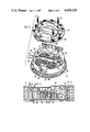
- FIG. 4 is a section on 4-4 of FIG. 1, also shown inverted so as to be more readily understood in conjunction with FIG. 3;
- FIG. 5 is a section along line 5--5 of FIG. 1 of the cord reel having, showing the interior of the hub in elevation.
- Cord reel 10 comprises a housing 12 including an annular radial wall 14 surrounded by a peripheral wall 16 which includes four portions 18 having a common radius of diameter centered on the centre of radial wall 14 and interconnected by lower shoulders 20 and upper shoulders 22 which are hollow.
- the shoulders 20,22 are open sided in the plane of radial wall 14, at 24.
- Fillets 26 close the shoulders 20,22 at the opposed axial end thereof, the fillets having an inwardly facing edge 28 which has an identical radius of curvature to peripheral wall portions 18, thereby forming a circular opening 30 in one axial side of the housing.
- the lower surface 32 of the lower pair of shoulders 18 is planar, whereby these shoulders serve to maintain housing 12 an upright position when desired.
- a handle 34 for carrying cord reel 10 connects between upper shoulders 20.
- Radial wall 14 has a relatively large circular opening 36 centrally located therein surrounded on the interior wall face of the radial wall by an annular wall 38, this last wall having a lip 40 on one surface thereof.
- Cord reel 10 further comprises a hollow, open ended hub 42, having an annular cheek wall 43 radiating from one axial end thereof, the diameter of the cheek wall being marginally less than the diameter of opening 30 in housing 12.
- the bore opening of hub 42 is such that the hub is a loose, telescopic fit about wall 38, the wall forming a trunnion bearing for the hub.
- the axial position of the hub is maintained by the distal end 44 of the hub which bears on the inner wall surface of radial wall 14, the hub being dimensioned so that cheek wall 43 then lays in the plane of opening 30.
- Hub 42 is retained in housing 12 by a cover plate 46 which inserts into opening 36 and engages lip 40.
- Cover plate 46 secures to a second cover plate 48 by machine screws 50, which engages a flange 52 formed on the interior wall of the hub adjacent cheek 43.
- Flange 52 is provided with openings 54 therein, and cover plate 48 with tabs 56 which engage with openings 54 so as to maintain the cover plate 48 in fixed, predetermined relationship with hub 42.
- a handle 58 extends from cheek wall 43 for imparting a rotary movement to hub 42.
- Cover plate 48 is provided with a concentered annular skirt wall 60 on the inner surface thereof, and cover plate 46 with a similar wall 62, although of lesser axial extent, which is telescopically received in skirt wall 60, the cover plates and skirt wall acting to form an enclosure 64 within hub 42.
- Cover plate 46 is provided with a plurality of small apertures 66 about the periphery thereof to assist in draining water which may be adventitiously introduced into enclosure 64.
- Cover plate 48 has a plurality of openings 68 in the face thereof extending therethrough for receiving the prongs of an electrical connector therein.
- a plurality of strip electrodes 70 are supported in radial directions by ribs 72 formed on the inner surface of cover plate 48, and axially by further ribs 74 formed on the inner surface of cover plate 46 transverse to ribs 72 when the cover plates are in their assembled relationship.
- Ribs 72 are provided with small transverse protrusions 76 which cooperate with transverse protrusions formed as part of the electrode structure, for example those referenced by the numeral 78, and which also function to stand the electrodes off from the ribs, so as not to trap moisture between the ribs and the electrodes by capillary action.
- the ribs provide an open support structure for the electrodes which facilitates the drainage of water such as may be adventitiously introduced thereto through prong openings 68.
- Cord reel 10 further comprises an electrical cord 80 which is storable on hub 42, and which may be withdrawn from housing 12, an opening 82 being provided in peripheral wall 16 for this purpose.
- a further opening 84 is formed in hub 42 to permit the passage of cord 80 therethrough.
- a still further slotted opening 86 is provided in skirt wall 60 of cover plate 48. Opening 84 is displaced from opening 54 by the same degree as opening 86 is displaced from tabs 56, whereby openings 84 and 86 are maintained in alignment to permit the passage of cord 80 to the interior of enclosure 64.
- Cord 80 is generally round, and has a nominal diameter of 8.5 mm.
- the width of hub 42, measured between the inner surfaces of radial housing wall 14 and cheek wall 43 has a dimension of some 36 mm, thereby permitting only four side by side turns of the cord in a layer of windings on the hub. It is found that with only four turns per layer a relatively regular winding of cord 80 onto hub 42 takes place as the hub is rotated, notwithstanding the absence of any cord feeding mechanism to control the lateral placement of the cord on the hub.
- Cord 80 is anchored to hub 42 by a tab 88 which projects below the periphery of wall 62 of cover plate 46, and which closes slotted opening 86 and acts to compress cord 80 therein.
- Slotted opening 86 is in general alignment with a maze 90 which comprises opposed ribs 92,94 formed on the inner surface of cover plate 48 generally parallel to ribs 72, having gate openings 96,98 and 100 therebetween which are staggered in the radial and axial directions to permit cord 80 to be threaded therethrough along a serpentine path.
- a tab 102 projects centrally from a rib 74 formed on the inner surface of cover plate 46 to urge cord 80 into gate 98, which is somewhat lower than the adjacent gates 96 and 100.
- circuit breaker 104 is supported within enclosure 64 from cover plate 48 and has a reset button 106 accessible on the outer surface of the cover plate.
- the body of circuit breaker 104 locates adjacent an opening 108 provided in skirt wall 60 of cover plate 48, which in turn aligns with an opening in hub 42 similar to opening 84 earlier described.
- Circuit breaker 104 is of a conventional structure, and for this reason the internal structure thereof is not specifically illustrated; such structure comprises a self heating bimetallic strip which triggers contacts to an open circuit position under given load conditions.
- the location of the circuit breaker 104 adjacent a window opening 84 in the hub 42 ensures that the circuit breaker will be in part responsive to any thermal build up caused by operating cord 80 when in its stored position.
- circuit breaker 104 will tend to trip under lower current loads when the cord reel is used with the cord stored thereon than when the cord is withdrawn from the reel.
- the long term overload trip current rating of circuit breaker 104 may be appreciably higher than where the circuit breaker is situated in a position where it is not sensitive to thermal build up within the cord reel.
- Thermal build up within housing 12 is reduced by providing a plurality of apertures 110 in cheek wall 43 which, together with openings 24 in shoulders 18, permit the circulation of converted air therethrough.
- the housing 12 of cord reel 10, together with the hub 42 and its cheek wall 43, are molded in an integrally skinned foamed polyethylene having a density of approximately 0.55 g/cc (ca 35 lbs/cuft.).
- the material has a somewhat waxy surface which resists the frictional binding of the material to itself and to most other materials including plasticized vinyl chloride, from which the outer cover of extension cord 80 is normally made, thereby facilitating the winding of cord 80 onto hub 42 and its slippage relative to radial wall 14 of the housing, and through opening 82 of the cord reel.
- the electrical and flammable properties of foamed polyethylene are not such as to be conductive to its use in forming a housing for exposed electrical contacts. For this reason I prefer to provide the enclosure 64 within the hub of a material having improved flammability and electrical properties, and cover plates 46,48 with their unitarily formed rib structure and skirt walls are suitably molded from a rigid polypropylene stabilized with a flame retardant such as antimony oxide or calcium carbonate.
Abstract
Description
Claims (8)
Priority Applications (1)
| Application Number | Priority Date | Filing Date | Title |
|---|---|---|---|
| US06/581,731 US4656320A (en) | 1984-02-21 | 1984-02-21 | Cord reel |
Applications Claiming Priority (1)
| Application Number | Priority Date | Filing Date | Title |
|---|---|---|---|
| US06/581,731 US4656320A (en) | 1984-02-21 | 1984-02-21 | Cord reel |
Publications (1)
| Publication Number | Publication Date |
|---|---|
| US4656320A true US4656320A (en) | 1987-04-07 |
Family
ID=24326348
Family Applications (1)
| Application Number | Title | Priority Date | Filing Date |
|---|---|---|---|
| US06/581,731 Expired - Lifetime US4656320A (en) | 1984-02-21 | 1984-02-21 | Cord reel |
Country Status (1)
| Country | Link |
|---|---|
| US (1) | US4656320A (en) |
Cited By (41)
| Publication number | Priority date | Publication date | Assignee | Title |
|---|---|---|---|---|
| US4725697A (en) * | 1986-08-28 | 1988-02-16 | Alert Stamping & Mfg. Co., Inc. | Extension cord reel and case |
| US5086988A (en) * | 1990-03-01 | 1992-02-11 | Lapoint David A | Car cover deployment and storage system |
| US5361879A (en) * | 1993-08-11 | 1994-11-08 | Lin Yeong Hwa | Extension cord reel |
| US5657841A (en) * | 1996-03-04 | 1997-08-19 | Morvan; Jacques | Extension cord reel assembly with ground fault interrupt outlets |
| US5662193A (en) * | 1995-12-18 | 1997-09-02 | Reel-Thing Innovations, Inc., The | Housing for a retractacle cord mechanism |
| USD384878S (en) * | 1996-08-23 | 1997-10-14 | Alert Stamping & Manufacturing Co., Inc. | Cord storage reel |
| US5803764A (en) * | 1996-12-26 | 1998-09-08 | The Reel-Thing Innovations Inc. | Method of weather proofing an opening through which an electrical cord passes, and associated apparatus |
| US5819894A (en) * | 1996-09-19 | 1998-10-13 | Nichido Kogyo Kabushiki Kaisha | Cable winding apparatus |
| GB2332991A (en) * | 1997-09-03 | 1999-07-07 | Ian Fussell | Electrical extension lead |
| US5934598A (en) * | 1996-08-23 | 1999-08-10 | Alert Stamping & Mfg. Co., Inc. | Manually operated cord storage reel |
| US6077109A (en) * | 1999-02-08 | 2000-06-20 | Prazoff; Michael | Extension socket |
| US6273354B1 (en) * | 1999-06-03 | 2001-08-14 | Alert Stamping & Mfg. Co., Inc. | Retracting extension cord reel |
| US20040004798A1 (en) * | 2002-07-08 | 2004-01-08 | Adc Dsl Systems, Inc. | Inrush limiter circuit |
| US6703889B2 (en) | 2002-02-14 | 2004-03-09 | Adc Dsl Systems, Inc. | In-rush current protection |
| US20050072645A1 (en) * | 2003-10-02 | 2005-04-07 | Kovacik James D. | Cord reel with electrical outlets |
| US20050224307A1 (en) * | 2001-12-28 | 2005-10-13 | Michael Steffen | Cable roller with a frequency converter device |
| US20060118377A1 (en) * | 2004-12-02 | 2006-06-08 | Li-Chun Lai | Extension cord holder |
| US20060186255A1 (en) * | 2005-02-22 | 2006-08-24 | Rooker Jeffrey F | Cord storage reel with built-in plug and receptacle panel |
| US20060266605A1 (en) * | 2005-05-31 | 2006-11-30 | Caamano Ramon A | Reel and reel housing |
| US20080012681A1 (en) * | 2006-05-26 | 2008-01-17 | Paul Kadar | Thermally protected electrical wiring device |
| US20080090434A1 (en) * | 2006-10-12 | 2008-04-17 | Yi-Ching Lin | Retractable extension socket |
| US20110193521A1 (en) * | 2008-10-09 | 2011-08-11 | Toyota Jidosha Kabushiki Kaisha | Connecting device |
| US20120262115A1 (en) * | 2009-12-28 | 2012-10-18 | Toyota Jidosha Kabushiki Kaisha | Wire housing device, vehicle equipped with the same, and power feeding device |
| US20130006226A1 (en) * | 2011-05-31 | 2013-01-03 | Hong Daniel Wei-Chen | Compact catheter assembly |
| US20130023148A1 (en) * | 2008-10-09 | 2013-01-24 | Wang Han Yap | Extension socket with cord storage and dispensing system |
| US20150048792A1 (en) * | 2013-08-15 | 2015-02-19 | John William Alford | Cord Reel Variable Current Thermal Management and Damage Detection |
| USD739448S1 (en) * | 2013-11-15 | 2015-09-22 | Southwire Company, Llc | Wire and cable package manufacturing jig |
| WO2016075348A1 (en) * | 2014-11-12 | 2016-05-19 | Fabricacion De Material Electrico, S.A. | Extension cord |
| GB2532933A (en) * | 2014-12-01 | 2016-06-08 | Intumescent Systems Ltd | Temporary enclosures |
| US9368303B2 (en) | 2010-08-31 | 2016-06-14 | Great Stuff, Inc. | Electrical cord reel with control system to limit overheating |
| US9484693B1 (en) * | 2015-06-11 | 2016-11-01 | Tyler James Richter | Cord organizing assembly |
| US20170031124A1 (en) * | 2012-02-29 | 2017-02-02 | Commscope Technologies Llc | Fiber optic cable packaging arrangement |
| CN106964922A (en) * | 2017-03-29 | 2017-07-21 | 浦江之音科技有限公司 | A kind of welder |
| CN107009058A (en) * | 2017-05-22 | 2017-08-04 | 宁波市协新机电科技有限公司 | A kind of welder |
| CN107175441A (en) * | 2017-06-08 | 2017-09-19 | 何昊充 | A kind of welder |
| US10265499B2 (en) | 2011-05-31 | 2019-04-23 | Compactcath, Inc. | Compact urinary catheter |
| US20190296481A1 (en) * | 2017-03-21 | 2019-09-26 | Logan Bailey | Cable management system for storing an managing an adapter box and a cable |
| US20190344678A1 (en) * | 2013-08-15 | 2019-11-14 | John Alford | Cord Reel Variable Current Thermal Management and Damage Detection |
| US10644492B2 (en) | 2017-10-13 | 2020-05-05 | Ralph Carl Magno | Cart for storing, transporting, and organizing a long electrical cord and a plurality of electrical outlets |
| US20200239266A1 (en) * | 2019-01-29 | 2020-07-30 | Brett Aldrich | Apparatus and method for providing tethered electrical power to autonomous unmanned ground vehicles |
| US11117737B2 (en) | 2012-11-12 | 2021-09-14 | Southwire Company, Llc | Wire and cable package |
Citations (8)
| Publication number | Priority date | Publication date | Assignee | Title |
|---|---|---|---|---|
| US2801303A (en) * | 1953-01-19 | 1957-07-30 | Grace N Pailing | Cord reel |
| US3837448A (en) * | 1972-12-15 | 1974-09-24 | L Hagstrom | Line cord caddy |
| DE2444807A1 (en) * | 1974-09-19 | 1976-04-01 | Bosch Gmbh Robert | Cable drum for extendable cables has elongated lateral window - exposing cables windings and graded in watts to indicate max. cable power at various extentions |
| US4244536A (en) * | 1979-10-31 | 1981-01-13 | Harrill Thomas D | Extension cord reel |
| US4282954A (en) * | 1980-02-11 | 1981-08-11 | Hill John O | Rewinder device |
| US4338497A (en) * | 1980-05-07 | 1982-07-06 | Noma Canada Ltd. | Extension cord reel set |
| US4467979A (en) * | 1982-02-01 | 1984-08-28 | Noma Inc. | Cord reel |
| US4520239A (en) * | 1982-09-30 | 1985-05-28 | Cable Electric Products, Inc. | Electrical cord reel and storage system |
-
1984
- 1984-02-21 US US06/581,731 patent/US4656320A/en not_active Expired - Lifetime
Patent Citations (8)
| Publication number | Priority date | Publication date | Assignee | Title |
|---|---|---|---|---|
| US2801303A (en) * | 1953-01-19 | 1957-07-30 | Grace N Pailing | Cord reel |
| US3837448A (en) * | 1972-12-15 | 1974-09-24 | L Hagstrom | Line cord caddy |
| DE2444807A1 (en) * | 1974-09-19 | 1976-04-01 | Bosch Gmbh Robert | Cable drum for extendable cables has elongated lateral window - exposing cables windings and graded in watts to indicate max. cable power at various extentions |
| US4244536A (en) * | 1979-10-31 | 1981-01-13 | Harrill Thomas D | Extension cord reel |
| US4282954A (en) * | 1980-02-11 | 1981-08-11 | Hill John O | Rewinder device |
| US4338497A (en) * | 1980-05-07 | 1982-07-06 | Noma Canada Ltd. | Extension cord reel set |
| US4467979A (en) * | 1982-02-01 | 1984-08-28 | Noma Inc. | Cord reel |
| US4520239A (en) * | 1982-09-30 | 1985-05-28 | Cable Electric Products, Inc. | Electrical cord reel and storage system |
Cited By (71)
| Publication number | Priority date | Publication date | Assignee | Title |
|---|---|---|---|---|
| US4725697A (en) * | 1986-08-28 | 1988-02-16 | Alert Stamping & Mfg. Co., Inc. | Extension cord reel and case |
| US5086988A (en) * | 1990-03-01 | 1992-02-11 | Lapoint David A | Car cover deployment and storage system |
| US5361879A (en) * | 1993-08-11 | 1994-11-08 | Lin Yeong Hwa | Extension cord reel |
| US5662193A (en) * | 1995-12-18 | 1997-09-02 | Reel-Thing Innovations, Inc., The | Housing for a retractacle cord mechanism |
| US5657841A (en) * | 1996-03-04 | 1997-08-19 | Morvan; Jacques | Extension cord reel assembly with ground fault interrupt outlets |
| US5934598A (en) * | 1996-08-23 | 1999-08-10 | Alert Stamping & Mfg. Co., Inc. | Manually operated cord storage reel |
| USD384878S (en) * | 1996-08-23 | 1997-10-14 | Alert Stamping & Manufacturing Co., Inc. | Cord storage reel |
| US5819894A (en) * | 1996-09-19 | 1998-10-13 | Nichido Kogyo Kabushiki Kaisha | Cable winding apparatus |
| US5803764A (en) * | 1996-12-26 | 1998-09-08 | The Reel-Thing Innovations Inc. | Method of weather proofing an opening through which an electrical cord passes, and associated apparatus |
| GB2332991A (en) * | 1997-09-03 | 1999-07-07 | Ian Fussell | Electrical extension lead |
| GB2332991B (en) * | 1997-09-03 | 2002-04-24 | Ian Clarke Fussell | Electrical extension lead or adaptor |
| US6077109A (en) * | 1999-02-08 | 2000-06-20 | Prazoff; Michael | Extension socket |
| US6273354B1 (en) * | 1999-06-03 | 2001-08-14 | Alert Stamping & Mfg. Co., Inc. | Retracting extension cord reel |
| US7044413B2 (en) * | 2001-12-28 | 2006-05-16 | Wacker Construction Equipment Ag | Cable roller with a frequency converter device |
| US20050224307A1 (en) * | 2001-12-28 | 2005-10-13 | Michael Steffen | Cable roller with a frequency converter device |
| US6703889B2 (en) | 2002-02-14 | 2004-03-09 | Adc Dsl Systems, Inc. | In-rush current protection |
| US6807039B2 (en) | 2002-07-08 | 2004-10-19 | Adc Dsl Systems, Inc. | Inrush limiter circuit |
| US20040004798A1 (en) * | 2002-07-08 | 2004-01-08 | Adc Dsl Systems, Inc. | Inrush limiter circuit |
| US20050072645A1 (en) * | 2003-10-02 | 2005-04-07 | Kovacik James D. | Cord reel with electrical outlets |
| US20060118377A1 (en) * | 2004-12-02 | 2006-06-08 | Li-Chun Lai | Extension cord holder |
| US7114603B2 (en) * | 2004-12-02 | 2006-10-03 | Li-Chun Lai | Extension cord holder |
| US20060186255A1 (en) * | 2005-02-22 | 2006-08-24 | Rooker Jeffrey F | Cord storage reel with built-in plug and receptacle panel |
| WO2006130583A3 (en) * | 2005-05-31 | 2007-03-29 | Great Stuff Inc | Improved reel and reel housing |
| US8201673B2 (en) | 2005-05-31 | 2012-06-19 | Great Stuff, Inc. | Temperature control system for electrical cord reel |
| US20060266605A1 (en) * | 2005-05-31 | 2006-11-30 | Caamano Ramon A | Reel and reel housing |
| WO2006130583A2 (en) * | 2005-05-31 | 2006-12-07 | Great Stuff, Inc. | Improved reel and reel housing |
| US20110141634A1 (en) * | 2005-05-31 | 2011-06-16 | Great Stuff, Inc. | Temperature control system for electrical cord reel |
| US7419038B2 (en) | 2005-05-31 | 2008-09-02 | Great Stuff, Inc. | Reel and reel housing |
| US20090057085A1 (en) * | 2005-05-31 | 2009-03-05 | Great Stuff, Inc. | Reel and reel housing |
| US20080012681A1 (en) * | 2006-05-26 | 2008-01-17 | Paul Kadar | Thermally protected electrical wiring device |
| US7467971B2 (en) * | 2006-10-12 | 2008-12-23 | Powertech Industrial Co., Ltd. | Retractable extension socket |
| US20080090434A1 (en) * | 2006-10-12 | 2008-04-17 | Yi-Ching Lin | Retractable extension socket |
| US20110193521A1 (en) * | 2008-10-09 | 2011-08-11 | Toyota Jidosha Kabushiki Kaisha | Connecting device |
| US8525476B2 (en) * | 2008-10-09 | 2013-09-03 | Toyota Jidosha Kabushiki Kaisha | Connecting device for supplying electric power from an outside power supply to a vehicle |
| US9225128B2 (en) * | 2008-10-09 | 2015-12-29 | Wang Han Yap | Extension socket with cord storage and dispensing system |
| US20130023148A1 (en) * | 2008-10-09 | 2013-01-24 | Wang Han Yap | Extension socket with cord storage and dispensing system |
| US20120262115A1 (en) * | 2009-12-28 | 2012-10-18 | Toyota Jidosha Kabushiki Kaisha | Wire housing device, vehicle equipped with the same, and power feeding device |
| US9073441B2 (en) * | 2009-12-28 | 2015-07-07 | Toyota Jidosha Kabushiki Kaisha | Wire housing device, vehicle equipped with the same, and power feeding device |
| US9368303B2 (en) | 2010-08-31 | 2016-06-14 | Great Stuff, Inc. | Electrical cord reel with control system to limit overheating |
| US20130006226A1 (en) * | 2011-05-31 | 2013-01-03 | Hong Daniel Wei-Chen | Compact catheter assembly |
| US8974438B2 (en) | 2011-05-31 | 2015-03-10 | Compactcath, Inc. | Compact catheter assembly |
| US10265499B2 (en) | 2011-05-31 | 2019-04-23 | Compactcath, Inc. | Compact urinary catheter |
| US8708999B2 (en) | 2011-05-31 | 2014-04-29 | Compactcath, Inc. | Compact catheter assembly |
| US8556884B2 (en) * | 2011-05-31 | 2013-10-15 | Compactcath, Inc. | Compact catheter assembly |
| US20170031124A1 (en) * | 2012-02-29 | 2017-02-02 | Commscope Technologies Llc | Fiber optic cable packaging arrangement |
| US10663685B2 (en) | 2012-02-29 | 2020-05-26 | Commscope Technologies Llc | Fiber optic cable packaging arrangement |
| US10078193B2 (en) | 2012-02-29 | 2018-09-18 | Commscope Technologies Llc | Fiber optic cable packaging arrangement |
| US9791655B2 (en) * | 2012-02-29 | 2017-10-17 | Commscope Technologies Llc | Fiber optic cable packaging arrangement |
| US11117737B2 (en) | 2012-11-12 | 2021-09-14 | Southwire Company, Llc | Wire and cable package |
| US11858719B2 (en) | 2012-11-12 | 2024-01-02 | Southwire Company, Llc | Wire and cable package |
| US9238416B2 (en) * | 2013-08-15 | 2016-01-19 | Telefonix, Incorporated | Cord reel variable current thermal management and damage detection |
| US20190344678A1 (en) * | 2013-08-15 | 2019-11-14 | John Alford | Cord Reel Variable Current Thermal Management and Damage Detection |
| US20160318412A1 (en) * | 2013-08-15 | 2016-11-03 | John Alford | Cord Reel Variable Current Thermal Management and Damage Detection |
| US20150048792A1 (en) * | 2013-08-15 | 2015-02-19 | John William Alford | Cord Reel Variable Current Thermal Management and Damage Detection |
| US10906417B2 (en) * | 2013-08-15 | 2021-02-02 | Konnectronix, Inc. | Cord reel variable current thermal management and damage detection |
| US20230081330A1 (en) * | 2013-08-15 | 2023-03-16 | John Alford | Cord Reel Variable Current Thermal Management and Damage Detection |
| US10214114B2 (en) * | 2013-08-15 | 2019-02-26 | Konnectronix, Inc. | Cord reel variable current thermal management and damage detection |
| US11505074B2 (en) * | 2013-08-15 | 2022-11-22 | Konnectronix, Inc. | Cord reel variable current thermal management and damage detection |
| USD739448S1 (en) * | 2013-11-15 | 2015-09-22 | Southwire Company, Llc | Wire and cable package manufacturing jig |
| WO2016075348A1 (en) * | 2014-11-12 | 2016-05-19 | Fabricacion De Material Electrico, S.A. | Extension cord |
| GB2532933A (en) * | 2014-12-01 | 2016-06-08 | Intumescent Systems Ltd | Temporary enclosures |
| GB2532933B (en) * | 2014-12-01 | 2020-09-23 | Intumescent Systems Ltd | Temporary enclosures |
| US9484693B1 (en) * | 2015-06-11 | 2016-11-01 | Tyler James Richter | Cord organizing assembly |
| US20190296481A1 (en) * | 2017-03-21 | 2019-09-26 | Logan Bailey | Cable management system for storing an managing an adapter box and a cable |
| US10938148B2 (en) * | 2017-03-21 | 2021-03-02 | Logan Bailey | Cable management system for storing and managing an adapter box and cable |
| CN106964922A (en) * | 2017-03-29 | 2017-07-21 | 浦江之音科技有限公司 | A kind of welder |
| CN107009058A (en) * | 2017-05-22 | 2017-08-04 | 宁波市协新机电科技有限公司 | A kind of welder |
| CN107009058B (en) * | 2017-05-22 | 2019-02-12 | 湖北泰业汽车零部件科技有限公司 | A kind of welder |
| CN107175441A (en) * | 2017-06-08 | 2017-09-19 | 何昊充 | A kind of welder |
| US10644492B2 (en) | 2017-10-13 | 2020-05-05 | Ralph Carl Magno | Cart for storing, transporting, and organizing a long electrical cord and a plurality of electrical outlets |
| US20200239266A1 (en) * | 2019-01-29 | 2020-07-30 | Brett Aldrich | Apparatus and method for providing tethered electrical power to autonomous unmanned ground vehicles |
Similar Documents
| Publication | Publication Date | Title |
|---|---|---|
| US4656320A (en) | Cord reel | |
| US5673360A (en) | Travel Humidifier | |
| CA1304339C (en) | Extension cord reel and case | |
| US5413501A (en) | Electrical outlet | |
| US5657841A (en) | Extension cord reel assembly with ground fault interrupt outlets | |
| US6991495B1 (en) | Power strip with self-contained ground fault circuit interrupter module | |
| US5899761A (en) | Power strip | |
| US4520239A (en) | Electrical cord reel and storage system | |
| CA2011897C (en) | Multiple outlet receptacle and mountings therefor | |
| US4484185A (en) | Safety plug adapter | |
| EP0527560B1 (en) | Outdoor electrical outlet cover | |
| US5135411A (en) | Multiple outlet receptacle and mountings therefor | |
| US6230860B1 (en) | Mobile phone battery charger with power cord winding mechanism | |
| US7554033B1 (en) | Environmentally Protected Wiring Device | |
| US4340267A (en) | Safety electrical plug | |
| US4771367A (en) | Electric plug with circuit breaker | |
| US3815078A (en) | Retractable extension cord unit | |
| US4442984A (en) | Electric cord reel | |
| US20070257764A1 (en) | Portable electrical receptacle with multiple heat sensors | |
| US4758184A (en) | Fused plug for electrical appliance cord | |
| US5384559A (en) | Fuse plug with replacement fuse storage | |
| CA1252078A (en) | Cord reel | |
| US2585070A (en) | Retractable electric extension cord switch | |
| US5137473A (en) | Fused protection device | |
| EP0421906A1 (en) | Cord storing power strip |
Legal Events
| Date | Code | Title | Description |
|---|---|---|---|
| AS | Assignment |
Owner name: NOMA INC PROVINCE OKNTARIO 375 KENNEDY RD SCARBORO Free format text: ASSIGNMENT OF ASSIGNORS INTEREST.;ASSIGNOR:MADDOCK, WILLIAM H.;REEL/FRAME:004232/0764 Effective date: 19840206 |
|
| STCF | Information on status: patent grant |
Free format text: PATENTED CASE |
|
| FPAY | Fee payment |
Year of fee payment: 4 |
|
| FPAY | Fee payment |
Year of fee payment: 8 |
|
| AS | Assignment |
Owner name: WOODS II INC., CANADA Free format text: ASSIGNMENT OF ASSIGNORS INTEREST;ASSIGNOR:NOMA, INC.;REEL/FRAME:009257/0838 Effective date: 19980521 |
|
| AS | Assignment |
Owner name: WOODS INDUSTRIES (CANADA) INC., CANADA Free format text: CHANGE OF NAME;ASSIGNOR:WOODS II INC.;REEL/FRAME:009267/0691 Effective date: 19980609 |
|
| REMI | Maintenance fee reminder mailed | ||
| FPAY | Fee payment |
Year of fee payment: 12 |
|
| SULP | Surcharge for late payment |