US4667259A - Non-magnetic part in magnetic head assembly - Google Patents
Non-magnetic part in magnetic head assembly Download PDFInfo
- Publication number
- US4667259A US4667259A US06/724,469 US72446985A US4667259A US 4667259 A US4667259 A US 4667259A US 72446985 A US72446985 A US 72446985A US 4667259 A US4667259 A US 4667259A
- Authority
- US
- United States
- Prior art keywords
- magnetic
- volume
- baal
- core
- tio
- Prior art date
- Legal status (The legal status is an assumption and is not a legal conclusion. Google has not performed a legal analysis and makes no representation as to the accuracy of the status listed.)
- Expired - Lifetime
Links
Images


Classifications
-
- G—PHYSICS
- G11—INFORMATION STORAGE
- G11B—INFORMATION STORAGE BASED ON RELATIVE MOVEMENT BETWEEN RECORD CARRIER AND TRANSDUCER
- G11B5/00—Recording by magnetisation or demagnetisation of a record carrier; Reproducing by magnetic means; Record carriers therefor
- G11B5/127—Structure or manufacture of heads, e.g. inductive
- G11B5/265—Structure or manufacture of a head with more than one gap for erasing, recording or reproducing on the same track
- G11B5/2652—Structure or manufacture of a head with more than one gap for erasing, recording or reproducing on the same track with more than one gap simultaneously operative
- G11B5/2654—Structure or manufacture of a head with more than one gap for erasing, recording or reproducing on the same track with more than one gap simultaneously operative for recording or erasing
- G11B5/2655—Structure or manufacture of a head with more than one gap for erasing, recording or reproducing on the same track with more than one gap simultaneously operative for recording or erasing with all the gaps disposed within the track or "guard band" between tracks, e.g. with erase gaps operative on track edges, with wide erase gap followed by narrow write gap
-
- G—PHYSICS
- G11—INFORMATION STORAGE
- G11B—INFORMATION STORAGE BASED ON RELATIVE MOVEMENT BETWEEN RECORD CARRIER AND TRANSDUCER
- G11B5/00—Recording by magnetisation or demagnetisation of a record carrier; Reproducing by magnetic means; Record carriers therefor
- G11B5/127—Structure or manufacture of heads, e.g. inductive
- G11B5/133—Structure or manufacture of heads, e.g. inductive with cores composed of particles, e.g. with dust cores, with ferrite cores with cores composed of isolated magnetic particles
Definitions
- the present invention relates to a non-magnetic part to be bonded to a magnetic core portion made of Ni-Zn ferrite in a magnetic head assembly.
- a magnetic head assembly is composed of three like layers joined in a sandwich structure, the center layer being a read/write layer and the outer layers being erase layers wherein each layer has a magnetic core portion having a magnetic gap formed by two legs and a non-magnetic spacer portion joined to one of the legs.
- the magnetic core portion is generally made of Ni-Zn ferrite, because it is readily machinable to a constant width, highly permeable for a high frequency A.C. magnetic flux and resistant to abrasion or wear.
- a magnetic core made of Mn-Zn in a read/write layer is utilized in a magnetic recording device where a high coercive force of recording medium is utilized in order to attain a higher writing density.
- a magnetic head assembly is provided with a non-magnetic part made of a ceramic material consisting of two phases, TiO 2 and Ba 2 Ti 9 O 20 which is bonded to a magnetic core portion made of Ni-Zn ferrite.
- the above-mentioned ceramic material consisting of two phases, TiO 2 and Ba 2 Ti 9 O 20 is too sensitive to composition variations.
- the mean thermal expansion coefficient measured in a temperature range of 100 to 400 degrees centigrade of a ceramic part having two phases TiO 2 and Ba 2 Ti 9 O 20 varies drastically depending on the volume ratio of TiO 2 to the total amount of TiO 2 and Ba 2 Ti 9 O 20 , and it causes a difficulty for a manufacturer to produce a ceramic material having the desired a mean thermal expansion coefficient in actual production. Previously it was necessary to perform a strict selection of the non-magnetic parts produced, comparing the expansion coefficient of each non-magnetic part with the coefficients desired.
- a non-magnetic part had a coefficient outside of the desired range was bonded to a Ni-Zn ferrite core, it caused some cracks in the core or an undesirable reduction of magnetic characteristics of the core because of strain induced stress in the core.
- the ceramic material which is a mixture of only TiO 2 and Ba 2 Ti 9 O 20 wears faster than a Ni-Zn ferrite core, when used as a non-magnetic portion in a magnetic head assembly which moves in contact with a magnetic recording medium.
- It is another object of the invention to provide a non-magnetic part bonded to a magnetic core portion made of Ni-Zn ferrite in a magnetic head assembly comprising a read/write head unit sandwiched by a pair of erasing magnetic head units, each head unit of which is comprised of a magnetic core portion and non-magnetic spacer bonded to one of legs separated by a magnetic gap in the magnetic core portion.
- a non-magnetic part bonded to a magnetic core portion made of Ni-Zn ferrite in a magnetic head assembly which is made of a ceramic material comprised of 30 to 50 volume % of TiO 2 and 70 to 50 volume % of Ba 2 Ti 9 O 20 and BaAl 2 Ti 5 O 14 wherein the volume ratio of Ba 2 Ti 9 O 20 to the total volume of Ba 2 Ti 9 O 20 and BaAl 2 Ti 5 O 14 is 0.05 to 0.5.
- FIG. 1 is a perspective view of a core assembly for a magnetic head assembly in which the invention is applied;
- FIGS. 3(a) and 3(b) are photomicrographs of the cross-section of non-magnetic parts having three phases according to the invention.
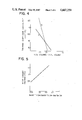
- FIG. 4 is a graph showing the mean thermal expansion coefficient variation versus the volume ratio of the phases contained in a non-magnetic material
- FIG. 5 is a graph showing the wear amount versus the volume ratio of BaAl 2 Ti 5 O 14 to the total amount of BaAl 2 Ti 5 O 14 and Ba 2 Ti 9 O 20 ;
- FIG. 6 is a schematic view of the apparatus to measure the amount of wear.
- FIG. 1 is a schematic illustration of a magnetic head assembly in accordance with an embodiment of the invention
- FIG. 2 is an exploded view of the magnetic head assembly shown in FIG. 1.
- a reference numeral 1 designates a read/write magnetic head core made of an Ni-Zn ferrite.
- a first reinforcer 2 made of a non-magnetic ceramics is bonded by means of a glass in parallel with the magnetic gap of the magnetic head core 1.
- a reference numeral 3 designates an erasing head which is composed of an L-shaped core 3a and an I-shaped core 3b made of Ni-Zn ferrite arranged to abutt each other to form a predetermined magnetic gap and glass-bonded to each other.
- An L-shaped second reinforcer 4 made of a non-magnetic ceramic is glass-bonded in parallel to the magnetic gap of the erasing head 3.
- a reference numeral 5 denote side plates.
- the second reinforcers 4 are positioned at both sides of the read/write magnetic head core 1, while the erasing magnetic head cores 3 are positioned at both sides of the first reinforcer 2 bonded in parallel to the gap of the read/write magnetic head core 1.
- the side plates 5 are placed at the outer sides of respective erasing head cores 3.
- the reinforcers 2 and 4 are all made of a ceramic material comprised of TiO 2 , Ba 2 Ti 9 O 20 and BaAl 2 Ti 5 O 14 .
- FIGS. 3(a) and 3(b) are photomicrographs of the cross-section of the parts 2 and 4 having the three phases TiO 2 , Ba 2 Ti 9 O 20 and BaAl 2 Ti 5 O 14 .
- the ceramic material shown in FIG. 3(a) was produced from 76.95 weight % TiO 2 , 20.95 weight % of BaCO 3 and 2.1 weight % of Al 2 O 3 .
- the ceramic material shown in FIG. 3(b) was produced from 76.2 weight % of TiO 2 , 20.2 weight % of BaCO 3 and 3.6 weight % of Al 2 O 3 .
- the black parts represent TiO 2 phase
- the gray parts represent BaAl 2 Ti 5 O 14
- the rather white parts represent Ba 2 Ti 9 O 20 as identified by a scanning electron beam type of microscope.
- the gray BaAl 2 Ti 5 O 14 phase increases, the rather white Ba 2 Ti 9 O 20 phase decreases, and each Ba 2 Ti 9 O 20 particle becomes smaller and smaller.
- the non-magnetic reinforcer according to the invention can be used in a magnetic head assembly described in U.S. Pat. No. 4,506,308 wherein a Mn-Zn ferrite is utilized as a read/write magnetic core material.
- the non-magnetic material produced according to the invention contains three phases TiO 2 , Ba 2 Ti 9 O 20 and BaAl 2 Ti 5 O 14 .
- ⁇ 1/1/deg. is defined as a coefficient of thermal expansion such as mm of change ( ⁇ mm) per mm (/mm) of length per degree centigrade (/deg.).
- the units of length cancel and do not effect the value measured for the coefficient, the units are simply those of length or ("1") or the length units can be omitted and the coefficient can be written as simply /degrees centigrade.
- This range is close to the thermal expansion coefficient of Ni-Zn ferrites, in order to avoid distortions or cracks in a magnetic core portion made of Ni-Zn ferrite during the bonding steps involving heating, due to the difference in their thermal expansion coefficients, if there is a large difference in coefficient of thermal expansion between the non-magnetic part and magnetic core part to be bonded to it.
- the ceramic material of the invention can be easily manufactured, because the variation of the coefficient depending on the volume ratio of TiO 2 to the total amount of TiO 2 , Ba 2 Ti 9 O 20 and BaAl 2 Ti 5 O 14 is less than one in the previous two phases of ceramic material.
- the invented material comprised of three phases has an excellent wear resistance which is close to one of Ni-Zn ferrite materials.
- the BaAl 2 Ti 5 O 14 phase serve to enhance the wear resistance and the controllability of the thermal expansion coefficient to be provided to the ceramic material.
- the variation of thermal expansion coefficients versus the volume ratio of TiO 2 to the total volume of the compositions contained in a material is shown in FIG. 4.
- the curves B and A represents respectively a ceramic material having no BaAl 2 Ti 5 O 14 phase and a ceramic material wherein about 70 volume % of Ba 2 Ti 9 O 20 phase is substituted by BaAl 2 Ti 5 O 14 phase.
- the variation dependence of thermal expansion coefficients on the volume ratio of TiO 2 to the total volume of the compositions contained in a material is reduced by BaAl 2 Ti 5 O 14 substitution for Ba 2 Ti 9 O 20 .
- the amount of TiO 2 contained in the non-magnetic part is 30 to 50 volume % in order to provide a thermal expansion coefficient in the range of 86 ⁇ 10 -7 ⁇ 1/1/deg. to 99 ⁇ 10 -7 ⁇ 1/1/deg. which is close to one of Ni-Zn ferrite material as shown in FIG. 4.
- the preferable volume ratio of BaAl 2 Ti 5 O 14 to the total volume of BaAl 2 Ti 5 O 14 and Ba 2 Ti 9 O 20 is one value in the range of 0.05 to 0.5, as shown in FIG. 5.
- Aluminum content in the ceramic material should not be excess, because the excess addition of Aluminum causes an apperance of undesirable phases as Al 2 O 3 and others in it.
- Some other oxides as SiO 2 , SrO, CaO, MgO, or ZrO 2 could be contained in the non-magnetic material in the invention without any serious deterioration of mechanical or magnetic characteristics of the material, if the content of SiO 2 is less than 0.5 weight % and the each content of the other oxides should not exceed 0.1 weight %.
- each phase it is preferable for the each phase to be distributed uniformly in the ceramic material invented.
- the mean particle size of each phase, TiO 2 , BaAl 2 Ti 5 O 14 or BaTi 9 O 20 is preferably less than 5 ⁇ m.
- BaAl 2 Ti 5 O 14 phase and BaTi 9 O 20 phase enclose the TiO 2 phase as shown in FIGS. 3(a) and 3(b).
- the volume ratio of pores to the total volume of a non-magnetic part in the invention is preferably less than 0.005, in order to enhance the wear resistance and the control of the thermal expansion coefficient.
- Titanium oxide, barium carbonate and aluminum oxide were mixed in a wet condition by a ball mill apparatus.
- the mixed material was sintered temporarily after it was dried.
- the temporarily sintered material was crushed and then milled.
- the milled powders were granulated with polyvinyl alcohol as binder material, and then compressed to be formed as a green body.
- various compositions of green bodies were produced, and then sintered at a temperature of 1300° C.
- the obtained products were further treated at 1200° C., 1000 atmospheric pressure and in Ar atmosphere for 1 hour. Subsequently they were annealed.
- the measurements of thermal expansion coefficient were performed at temperatures ranging 100° to 400° C., in order to calculate the mean value of the coefficients in the temperature range.
- the measurements of wear resistance were performed by the apparatus shown in FIG. 6, where the test piece 34 having a shape of 3 ⁇ 3 ⁇ 10 mm was loaded by 100 grams of weight, for one hour.
- the relative amount of wear for each test piece was measured, where the amount of wear for a Ni-Zn ferrite piece was normalized as equal to 1.
- the various phases contained in the test pieces were identified by a scanning electron beam type of microscope and the cross sections of some test pieces were photographed.
- the typical photomicrographs of the phases contained in the non-magnetic part according to the invention are shown in FIGS. 3(a) and 3(b).
Abstract
Description
Claims (8)
Applications Claiming Priority (2)
| Application Number | Priority Date | Filing Date | Title |
|---|---|---|---|
| JP59-79254 | 1984-04-19 | ||
| JP59079254A JPS60226455A (en) | 1984-04-19 | 1984-04-19 | Non-magnetic ceramic for magnetic head |
Publications (1)
| Publication Number | Publication Date |
|---|---|
| US4667259A true US4667259A (en) | 1987-05-19 |
Family
ID=13684713
Family Applications (1)
| Application Number | Title | Priority Date | Filing Date |
|---|---|---|---|
| US06/724,469 Expired - Lifetime US4667259A (en) | 1984-04-19 | 1985-04-18 | Non-magnetic part in magnetic head assembly |
Country Status (2)
| Country | Link |
|---|---|
| US (1) | US4667259A (en) |
| JP (1) | JPS60226455A (en) |
Cited By (24)
| Publication number | Priority date | Publication date | Assignee | Title |
|---|---|---|---|---|
| US4736122A (en) * | 1987-04-15 | 1988-04-05 | Echlin Inc. | Read head for Wiegand wire |
| EP0533162A1 (en) * | 1991-09-18 | 1993-03-24 | Ngk Spark Plug Co., Ltd | BaO-xTiO2 dielectric ceramic composition |
| US8970537B1 (en) | 2013-09-30 | 2015-03-03 | Synaptics Incorporated | Matrix sensor for image touch sensing |
| US9081457B2 (en) | 2013-10-30 | 2015-07-14 | Synaptics Incorporated | Single-layer muti-touch capacitive imaging sensor |
| US9081453B2 (en) | 2012-01-12 | 2015-07-14 | Synaptics Incorporated | Single layer capacitive imaging sensors |
| US9274662B2 (en) | 2013-10-18 | 2016-03-01 | Synaptics Incorporated | Sensor matrix pad for performing multiple capacitive sensing techniques |
| US9298325B2 (en) | 2013-09-30 | 2016-03-29 | Synaptics Incorporated | Processing system for a capacitive sensing device |
| US9459367B2 (en) | 2013-10-02 | 2016-10-04 | Synaptics Incorporated | Capacitive sensor driving technique that enables hybrid sensing or equalization |
| US9542023B2 (en) | 2013-08-07 | 2017-01-10 | Synaptics Incorporated | Capacitive sensing using matrix electrodes driven by routing traces disposed in a source line layer |
| US9690397B2 (en) | 2014-05-20 | 2017-06-27 | Synaptics Incorporated | System and method for detecting an active pen with a matrix sensor |
| US9715304B2 (en) | 2015-06-30 | 2017-07-25 | Synaptics Incorporated | Regular via pattern for sensor-based input device |
| US9720541B2 (en) | 2015-06-30 | 2017-08-01 | Synaptics Incorporated | Arrangement of sensor pads and display driver pads for input device |
| US9778713B2 (en) | 2015-01-05 | 2017-10-03 | Synaptics Incorporated | Modulating a reference voltage to preform capacitive sensing |
| US9798429B2 (en) | 2014-02-28 | 2017-10-24 | Synaptics Incorporated | Guard electrodes in a sensing stack |
| US9927832B2 (en) | 2014-04-25 | 2018-03-27 | Synaptics Incorporated | Input device having a reduced border region |
| US9939972B2 (en) | 2015-04-06 | 2018-04-10 | Synaptics Incorporated | Matrix sensor with via routing |
| US10037112B2 (en) | 2015-09-30 | 2018-07-31 | Synaptics Incorporated | Sensing an active device'S transmission using timing interleaved with display updates |
| US10042489B2 (en) | 2013-09-30 | 2018-08-07 | Synaptics Incorporated | Matrix sensor for image touch sensing |
| US10067587B2 (en) | 2015-12-29 | 2018-09-04 | Synaptics Incorporated | Routing conductors in an integrated display device and sensing device |
| US10095948B2 (en) | 2015-06-30 | 2018-10-09 | Synaptics Incorporated | Modulation scheme for fingerprint sensing |
| US10126890B2 (en) | 2015-12-31 | 2018-11-13 | Synaptics Incorporated | Single layer sensor pattern and sensing method |
| US10133421B2 (en) | 2014-04-02 | 2018-11-20 | Synaptics Incorporated | Display stackups for matrix sensor |
| US10175827B2 (en) | 2014-12-23 | 2019-01-08 | Synaptics Incorporated | Detecting an active pen using a capacitive sensing device |
| US10488994B2 (en) | 2015-09-07 | 2019-11-26 | Synaptics Incorporated | Single layer capacitive sensor pattern |
Citations (10)
| Publication number | Priority date | Publication date | Assignee | Title |
|---|---|---|---|---|
| US3819990A (en) * | 1971-12-29 | 1974-06-25 | Matsushita Electric Ind Co Ltd | Thin-film capacitor and method for the fabrication thereof |
| US3846840A (en) * | 1973-08-10 | 1974-11-05 | Ibm | Read/write and longitudinal edge erase head assembly having multiple similarly shaped layers |
| US4055438A (en) * | 1971-06-02 | 1977-10-25 | Ngk Insulators, Ltd. | Barium titanate ceramic |
| JPS54143217A (en) * | 1978-04-28 | 1979-11-08 | Tdk Corp | Magnetic head |
| JPS5589915A (en) * | 1978-12-28 | 1980-07-08 | Matsushita Electric Ind Co Ltd | Magnetic head of wear resistant performance |
| US4222783A (en) * | 1978-02-06 | 1980-09-16 | Ngk Insulators, Ltd. | Barium titanate series ceramics having a positive temperature coefficient of electric resistance |
| US4392167A (en) * | 1980-06-18 | 1983-07-05 | U.S. Philips Corporation | Magnetic head, method of producing the magnetic head |
| US4406722A (en) * | 1982-05-03 | 1983-09-27 | International Business Machines Corp. | Diffusion bonding of dissimilar ceramics |
| US4430440A (en) * | 1981-05-29 | 1984-02-07 | Sumitomo Special Metal Co. Ltd. | Magnetic head slider material |
| US4443825A (en) * | 1981-12-30 | 1984-04-17 | North American Philips Corporation | Magnetic head pole piece mount of TiO2 -CaO |
Family Cites Families (2)
| Publication number | Priority date | Publication date | Assignee | Title |
|---|---|---|---|---|
| JPS5229766A (en) * | 1975-09-01 | 1977-03-05 | Asahi Kagaku Kenkyusho:Kk | Fluid flow detector |
| JPS6029669B2 (en) * | 1981-05-22 | 1985-07-11 | 日立金属株式会社 | Non-magnetic ceramics for magnetic heads |
-
1984
- 1984-04-19 JP JP59079254A patent/JPS60226455A/en active Pending
-
1985
- 1985-04-18 US US06/724,469 patent/US4667259A/en not_active Expired - Lifetime
Patent Citations (10)
| Publication number | Priority date | Publication date | Assignee | Title |
|---|---|---|---|---|
| US4055438A (en) * | 1971-06-02 | 1977-10-25 | Ngk Insulators, Ltd. | Barium titanate ceramic |
| US3819990A (en) * | 1971-12-29 | 1974-06-25 | Matsushita Electric Ind Co Ltd | Thin-film capacitor and method for the fabrication thereof |
| US3846840A (en) * | 1973-08-10 | 1974-11-05 | Ibm | Read/write and longitudinal edge erase head assembly having multiple similarly shaped layers |
| US4222783A (en) * | 1978-02-06 | 1980-09-16 | Ngk Insulators, Ltd. | Barium titanate series ceramics having a positive temperature coefficient of electric resistance |
| JPS54143217A (en) * | 1978-04-28 | 1979-11-08 | Tdk Corp | Magnetic head |
| JPS5589915A (en) * | 1978-12-28 | 1980-07-08 | Matsushita Electric Ind Co Ltd | Magnetic head of wear resistant performance |
| US4392167A (en) * | 1980-06-18 | 1983-07-05 | U.S. Philips Corporation | Magnetic head, method of producing the magnetic head |
| US4430440A (en) * | 1981-05-29 | 1984-02-07 | Sumitomo Special Metal Co. Ltd. | Magnetic head slider material |
| US4443825A (en) * | 1981-12-30 | 1984-04-17 | North American Philips Corporation | Magnetic head pole piece mount of TiO2 -CaO |
| US4406722A (en) * | 1982-05-03 | 1983-09-27 | International Business Machines Corp. | Diffusion bonding of dissimilar ceramics |
Non-Patent Citations (1)
| Title |
|---|
| Secrist et al., Ceramic Material for Recording Heads, vol. 12, No. 6, Nov. 1969, IBM. * |
Cited By (35)
| Publication number | Priority date | Publication date | Assignee | Title |
|---|---|---|---|---|
| US4736122A (en) * | 1987-04-15 | 1988-04-05 | Echlin Inc. | Read head for Wiegand wire |
| EP0533162A1 (en) * | 1991-09-18 | 1993-03-24 | Ngk Spark Plug Co., Ltd | BaO-xTiO2 dielectric ceramic composition |
| US9182861B2 (en) | 2012-01-12 | 2015-11-10 | Synaptics Incoporated | Single layer capacitive imaging sensors |
| US9817533B2 (en) | 2012-01-12 | 2017-11-14 | Synaptics Incorporated | Single layer capacitive imaging sensors |
| US9081453B2 (en) | 2012-01-12 | 2015-07-14 | Synaptics Incorporated | Single layer capacitive imaging sensors |
| US9542023B2 (en) | 2013-08-07 | 2017-01-10 | Synaptics Incorporated | Capacitive sensing using matrix electrodes driven by routing traces disposed in a source line layer |
| US9552089B2 (en) | 2013-08-07 | 2017-01-24 | Synaptics Incorporated | Capacitive sensing using a matrix electrode pattern |
| US9778790B2 (en) | 2013-09-30 | 2017-10-03 | Synaptics Incorporated | Matrix sensor for image touch sensing |
| US9298325B2 (en) | 2013-09-30 | 2016-03-29 | Synaptics Incorporated | Processing system for a capacitive sensing device |
| US10042489B2 (en) | 2013-09-30 | 2018-08-07 | Synaptics Incorporated | Matrix sensor for image touch sensing |
| US10088951B2 (en) | 2013-09-30 | 2018-10-02 | Synaptics Incorporated | Matrix sensor for image touch sensing |
| US8970537B1 (en) | 2013-09-30 | 2015-03-03 | Synaptics Incorporated | Matrix sensor for image touch sensing |
| US9760212B2 (en) | 2013-09-30 | 2017-09-12 | Synaptics Incorported | Matrix sensor for image touch sensing |
| US9459367B2 (en) | 2013-10-02 | 2016-10-04 | Synaptics Incorporated | Capacitive sensor driving technique that enables hybrid sensing or equalization |
| US9274662B2 (en) | 2013-10-18 | 2016-03-01 | Synaptics Incorporated | Sensor matrix pad for performing multiple capacitive sensing techniques |
| US9483151B2 (en) | 2013-10-30 | 2016-11-01 | Synaptics Incorporated | Single layer multi-touch capacitive imaging sensor |
| US9081457B2 (en) | 2013-10-30 | 2015-07-14 | Synaptics Incorporated | Single-layer muti-touch capacitive imaging sensor |
| US9798429B2 (en) | 2014-02-28 | 2017-10-24 | Synaptics Incorporated | Guard electrodes in a sensing stack |
| US10133421B2 (en) | 2014-04-02 | 2018-11-20 | Synaptics Incorporated | Display stackups for matrix sensor |
| US9927832B2 (en) | 2014-04-25 | 2018-03-27 | Synaptics Incorporated | Input device having a reduced border region |
| US9690397B2 (en) | 2014-05-20 | 2017-06-27 | Synaptics Incorporated | System and method for detecting an active pen with a matrix sensor |
| US10175827B2 (en) | 2014-12-23 | 2019-01-08 | Synaptics Incorporated | Detecting an active pen using a capacitive sensing device |
| US9778713B2 (en) | 2015-01-05 | 2017-10-03 | Synaptics Incorporated | Modulating a reference voltage to preform capacitive sensing |
| US10795471B2 (en) | 2015-01-05 | 2020-10-06 | Synaptics Incorporated | Modulating a reference voltage to perform capacitive sensing |
| US10990148B2 (en) | 2015-01-05 | 2021-04-27 | Synaptics Incorporated | Central receiver for performing capacitive sensing |
| US11693462B2 (en) | 2015-01-05 | 2023-07-04 | Synaptics Incorporated | Central receiver for performing capacitive sensing |
| US9939972B2 (en) | 2015-04-06 | 2018-04-10 | Synaptics Incorporated | Matrix sensor with via routing |
| US10095948B2 (en) | 2015-06-30 | 2018-10-09 | Synaptics Incorporated | Modulation scheme for fingerprint sensing |
| US9720541B2 (en) | 2015-06-30 | 2017-08-01 | Synaptics Incorporated | Arrangement of sensor pads and display driver pads for input device |
| US9715304B2 (en) | 2015-06-30 | 2017-07-25 | Synaptics Incorporated | Regular via pattern for sensor-based input device |
| US10488994B2 (en) | 2015-09-07 | 2019-11-26 | Synaptics Incorporated | Single layer capacitive sensor pattern |
| US10037112B2 (en) | 2015-09-30 | 2018-07-31 | Synaptics Incorporated | Sensing an active device'S transmission using timing interleaved with display updates |
| US10067587B2 (en) | 2015-12-29 | 2018-09-04 | Synaptics Incorporated | Routing conductors in an integrated display device and sensing device |
| US10126890B2 (en) | 2015-12-31 | 2018-11-13 | Synaptics Incorporated | Single layer sensor pattern and sensing method |
| US11093058B2 (en) | 2015-12-31 | 2021-08-17 | Synaptics Incorporated | Single layer sensor pattern and sensing method |
Also Published As
| Publication number | Publication date |
|---|---|
| JPS60226455A (en) | 1985-11-11 |
Similar Documents
| Publication | Publication Date | Title |
|---|---|---|
| US4667259A (en) | Non-magnetic part in magnetic head assembly | |
| Warshaw et al. | Comparison of strength of triaxial porcelains containing alumina and silica | |
| US4406722A (en) | Diffusion bonding of dissimilar ceramics | |
| US3735052A (en) | Magnetic head assembly using titanium dioxide and barium titanate slider | |
| US5031064A (en) | Magnetic head having a slider member characterized by improved wear resistance | |
| US4441132A (en) | Magnetic head device | |
| US5034285A (en) | Magnetic head | |
| US5010431A (en) | Flying-type composite magnetic head | |
| EP0137134B1 (en) | A magnetic head having a non-magnetic substrate | |
| JPS585451B2 (en) | magnetic head | |
| EP0085794B1 (en) | Magnetic head construction | |
| KR100690460B1 (en) | Non-magnetic substrate for a magnetic head and magnetic head | |
| US4489168A (en) | Composition of matter for use in manufacturing non-magnetic parts of a magnetic head and method of manufacturing the composition | |
| JPS6337819A (en) | Floating type magnetic head for magnetic disk device | |
| JP3825079B2 (en) | Manufacturing method of non-magnetic ceramics | |
| US5404259A (en) | Magnetic head having high wear resistance and non-magnetic substrate used in the magnetic head | |
| JPS6140869A (en) | Ceramic composition for magnetic head reinforcement | |
| US5764455A (en) | Magnetic head | |
| KR0143068B1 (en) | A method of oxide magnetized material | |
| JP2622078B2 (en) | Manufacturing method of non-magnetic ceramics for magnetic head | |
| Monforte et al. | Pressure sintering of MnZn and NiZn ferrites | |
| JPH09221358A (en) | Production of non-magnetic substrate for magnetic head | |
| JP3078302B2 (en) | Non-magnetic ceramic composition | |
| JPS6297115A (en) | Magnetic head | |
| JPS59217624A (en) | Polycrystalline ferrite |
Legal Events
| Date | Code | Title | Description |
|---|---|---|---|
| AS | Assignment |
Owner name: HITACHI METALS, LTD., 1-2, MARUNOUCHI 2-CHOME, CHI Free format text: ASSIGNMENT OF ASSIGNORS INTEREST.;ASSIGNORS:UCHIDA, NORIAKI;USHIJIMA, MAKOTO;YANAGISAWA, ETSUO;REEL/FRAME:004396/0963 Effective date: 19850402 |
|
| STCF | Information on status: patent grant |
Free format text: PATENTED CASE |
|
| FEPP | Fee payment procedure |
Free format text: PAYOR NUMBER ASSIGNED (ORIGINAL EVENT CODE: ASPN); ENTITY STATUS OF PATENT OWNER: LARGE ENTITY |
|
| FPAY | Fee payment |
Year of fee payment: 4 |
|
| FEPP | Fee payment procedure |
Free format text: PAYOR NUMBER ASSIGNED (ORIGINAL EVENT CODE: ASPN); ENTITY STATUS OF PATENT OWNER: LARGE ENTITY Free format text: PAYER NUMBER DE-ASSIGNED (ORIGINAL EVENT CODE: RMPN); ENTITY STATUS OF PATENT OWNER: LARGE ENTITY |
|
| FPAY | Fee payment |
Year of fee payment: 8 |
|
| FPAY | Fee payment |
Year of fee payment: 12 |
|
| AS | Assignment |
Owner name: IP TRADING JAPAN CO., LTD., JAPAN Free format text: ASSIGNMENT OF ASSIGNORS INTEREST;ASSIGNOR:HITACHI METALS, LTD.;REEL/FRAME:014373/0044 Effective date: 20030806 |
|
| AS | Assignment |
Owner name: HITACHI METALS, LTD., JAPAN Free format text: CHANGE OF ADDRESS OF ASSIGNEE;ASSIGNOR:HITACHI METALS, LTD.;REEL/FRAME:014822/0110 Effective date: 20030822 |
|
| AS | Assignment |
Owner name: ALPS ELECTRIC CO., LTD., JAPAN Free format text: ASSIGNMENT OF ASSIGNORS INTEREST;ASSIGNOR:IP TRADING JAPAN CO., LTD.;REEL/FRAME:014462/0634 Effective date: 20040301 |