US4668489A - Method for treating gas streams - Google Patents
Method for treating gas streams Download PDFInfo
- Publication number
- US4668489A US4668489A US06/719,550 US71955085A US4668489A US 4668489 A US4668489 A US 4668489A US 71955085 A US71955085 A US 71955085A US 4668489 A US4668489 A US 4668489A
- Authority
- US
- United States
- Prior art keywords
- granules
- bed
- sorbent material
- gas
- accordance
- Prior art date
- Legal status (The legal status is an assumption and is not a legal conclusion. Google has not performed a legal analysis and makes no representation as to the accuracy of the status listed.)
- Expired - Lifetime
Links
Images


Classifications
-
- B—PERFORMING OPERATIONS; TRANSPORTING
- B01—PHYSICAL OR CHEMICAL PROCESSES OR APPARATUS IN GENERAL
- B01D—SEPARATION
- B01D53/00—Separation of gases or vapours; Recovering vapours of volatile solvents from gases; Chemical or biological purification of waste gases, e.g. engine exhaust gases, smoke, fumes, flue gases, aerosols
- B01D53/34—Chemical or biological purification of waste gases
- B01D53/46—Removing components of defined structure
- B01D53/48—Sulfur compounds
- B01D53/50—Sulfur oxides
- B01D53/508—Sulfur oxides by treating the gases with solids
-
- B—PERFORMING OPERATIONS; TRANSPORTING
- B01—PHYSICAL OR CHEMICAL PROCESSES OR APPARATUS IN GENERAL
- B01D—SEPARATION
- B01D53/00—Separation of gases or vapours; Recovering vapours of volatile solvents from gases; Chemical or biological purification of waste gases, e.g. engine exhaust gases, smoke, fumes, flue gases, aerosols
- B01D53/34—Chemical or biological purification of waste gases
- B01D53/46—Removing components of defined structure
- B01D53/68—Halogens or halogen compounds
- B01D53/685—Halogens or halogen compounds by treating the gases with solids
-
- B—PERFORMING OPERATIONS; TRANSPORTING
- B01—PHYSICAL OR CHEMICAL PROCESSES OR APPARATUS IN GENERAL
- B01D—SEPARATION
- B01D2257/00—Components to be removed
- B01D2257/20—Halogens or halogen compounds
- B01D2257/204—Inorganic halogen compounds
- B01D2257/2045—Hydrochloric acid
-
- B—PERFORMING OPERATIONS; TRANSPORTING
- B01—PHYSICAL OR CHEMICAL PROCESSES OR APPARATUS IN GENERAL
- B01D—SEPARATION
- B01D2257/00—Components to be removed
- B01D2257/20—Halogens or halogen compounds
- B01D2257/204—Inorganic halogen compounds
- B01D2257/2047—Hydrofluoric acid
Definitions
- This invention relates to the treatment of gas streams and is more particularly concerned with the removal of pollutants from waste gases associated with industrial and utility processes.
- the invention is especially useful, for example, in the removal of sulfur compounds (e.g., gaseous SO 2 ) from waste gases generated by the combustion of sulfur-bearing fossil fuels in boilers and the like.
- sulfur compounds e.g., gaseous SO 2
- halogen compounds such as chlorides (e.g., gaseous HCl) and fluorides (e.g., gaseous HF)
- dry sorbent injection systems represent perhaps the most attractive alternative to wet scrubbers among previously known flue gas desulfurization techniques.
- the potential operational and cost advantages of this approach (which basically involves the injection of finely divided dry sorbent material directly into a flue gas stream) are readily apparent, as the need for water or the like is eliminated while advantage can still be taken of less expensive sorbent materials.
- attempts to implement dry sorbent injection for SO 2 control have, by and large, proved disappointing--primarily due to physical limitations on reaction kinetics.
- Recent attempts at dry injection in conjunction with baghouse dust collectors have provided some encouraging results, but this approach still faces significant technical problems and has yet to be proven commercially feasible.
- the invention may be used to particular advantage in the control of SO 2 and in the control of halogen compounds--for example, chlorides such as HCl generated by the incineration of solid waste and fluorides such as HF generated by ceramic and glass furnaces, electric slag remelting operations, and aluminum smelting operations.
- halogen compounds for example, chlorides such as HCl generated by the incineration of solid waste and fluorides such as HF generated by ceramic and glass furnaces, electric slag remelting operations, and aluminum smelting operations.
- the invention relates to the treatment of gas streams using granular bed filters, devices which are well known in the art and commercially proven (especially in connection with the removal of particulate pollutants such as fly ash and the like). More particularly, it has been found in accordance with the invention that by passing a waste gas stream through a granular bed filter which contains granules coated with a thin layer of sorbent material, an undesired gaseous constituent can be removed from the gas stream with remarkable efficiency. The gaseous constituent is removed by reaction with the sorbent coating on the bed granules which forms a residue that is retained in the filter bed.
- the present invention overcomes the various problems associated with dry injection sorbent reaction systems and further provides the additional capability of simultaneous, highly efficient removal of particulates entrained in the gas stream by virtue of the use of granular bed filters.
- the invention thus offers significant advantages in regard to both equipment costs and overall system operation.
- the invention provides a method of treating a gas stream containing a gaseous constituent to be removed, comprising providing a granular bed filter, supplying to the bed of the filter granules of a first material having deposited thereon a coating of a second material which is a sorbent reactive with the gaseous constituent and passing the gas stream through the granular bed filter for contacting the gas stream with the sorbent material.
- the method may further include removing granules from the bed of the granular bed filter after a portion of the gas stream has been in contact with the sorbent material, removing reacted sorbent material from the removed granules, coating the removed granules with further sorbent material and feeding them back to the granular bed filter.
- apparatus for treating a gas stream containing a gaseous constituent to be removed comprises a granular bed filter adapted for the passage of the gas stream therethrough, the filter including a granular bed containing granules of a first material having deposited thereon a coating of a second material which is a sorbent reactive with the gaseous constituent.
- the apparatus may also include means for removing granules from the bed of the filter, means for removing reacted sorbent material from the removed granules, means including a further granular bed for coating the last-mentioned granules with further sorbent material, and means for supplying those granules from the further bed to the filter bed.
- aspects of the invention pertain, inter alia, to electrification of the granules in the filter bed for simultaneous removal of particulates entrained in the gas stream, methods and apparatus for coating the bed granules with sorbent material and specific applications of the invention in the treatment of gas streams containing gaseous SO 2 , HCl, or HF.
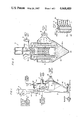
- FIG. 1 is a diagrammatic representation of apparatus for treating a gas stream in accordance with the invention
- FIG. 2 is a diagrammatic view, shown partly in section, of a granular bed filter of a preferred type for use in the apparatus of FIG. 1;
- FIG. 3 is an explanatory diagram
- FIG. 4 is a diagrammatic view, shown partly in section, of apparatus for coating granules in accordance with the invention.
- FIG. 5 is a view similar to FIG. 4, showing a second form of apparatus for coating granules in accordance with the invention
- FIG. 6 is another view similar to FIG. 4, showing a third form of apparatus for coating granules in accordance with the invention:
- FIG. 7 is a plot showing test results obtained from a pilot emission control installation in accordance with the invention.
- FIG. 1 shows preferred apparatus for carrying out a method of treating a gas stream in accordance with the invention, including a granular bed filter A and various peripheral components B-F which will be discussed in more detail shortly.
- the granular bed filter A be of the electrified moving bed type as described, for example, in U.S. Pat. Nos. 4,308,036; 4,374,652 or 4,505,723 (all issued to the assigneee hereof and incorporated herein by reference).
- certain advantages of the invention may be obtained by using other types of granular bed filters.
- a granular bed filter of the type described in the last-mentioned patent has been assumed and is shown diagrammatically in FIG. 2.
- the basic characteristics of the granular bed filter A will now be generally described.
- the granular bed filter A comprises an ionizer section 10 and a filter section 12.
- a gas stream to be treated enters the ionizer section 10 through an inlet 14 and then flows through the filter section 12 into an outlet plenum 16 which leads to an outlet port 18.
- the ionizer section 10 includes three ionizer disks 20 which are mounted on a rotatable shaft 22 disposed axially within the ionizer section 10.
- the disks 20 are provided with radially projecting needle electrodes such as 24 to which a high voltage is applied for creating a corona discharge which emanates from the needle tips, thereby electrically charging particulates entrained in the gas stream, as described more fully in the corresponding patent.
- the filter section 12 includes, inter alia, an inner cylindrical louver cage 26 and an outer cylindrical louver cage 28 which respectively form inner and outer retaining structures for a tubular portion 30a of a granular bed.
- the granular bed also includes a lower portion 30b supported by a conical outlet hopper 32.
- the granular bed 30a, 30b continuously moves downward through the granular bed filter A, the movement of the bed being achieved by removing granules from the bed through an exit port 34 at the base of the conical outlet hopper 32 and supplying additional granules to the bed through a feed line 36 near the top of the granular bed filter A, above filter section 12.
- the gas flow path in filter section 12 is split, a portion of the gas stream flowing radially outward of the louver cage 26 through the tubular portion 30a of the granular bed, the remainder flowing through the lower portion 30b of the granular bed substantially in counterflow to the movement of the bed granules.
- the filter section 12 be designed to provide a radial gas flow of approximately 80-90% of the gas stream and a counterflow of the remaining 10-20%.
- electrification of the granular bed 30a, 30b is effected by a bed electrode 38 to which a high voltage is applied relative to the louver cages 26 and 28 which are grounded as shown in FIG. 3.
- the electric field created between the bed electrode 38 and the louver cages 26 and 28 polarizes the bed granules, causing the electrically charged particulates in the gas stream to adhere to the granules.
- the granular bed filter A is supplied with granules coated with a thin layer of a sorbent material which is reactive with the gaseous constituent.
- a sorbent material which is reactive with the gaseous constituent.
- the sorbent coating on the granules thus reacts with the undesired constituent of the gas stream to form a residue (reacted sorbent) which remains on the granules in the filter bed, thereby removing the constituent from the gas stream.
- particulate matter is simultaneously removed from the gas stream with high efficiency by virtue of the basic characteristics of the preferred granular bed filter.
- particulates contained in the gas stream are retained in the filter bed by the "electromechanical freezing” effect described in U.S. Pat. No. 4,374,652, previously incorporated by reference. (Basically, this effect causes the granule-particulate mixture to move downwardly within the granular bed filter as a "frozen” or rigid plug.) Reacted sorbent material is similarly frozen in the filter bed.
- the electromechanical freezing effect generally permits the use of a wider range of granule flow rates through the filter bed and therefore provides broad sorbent usage rate capabilities.
- peripheral components B-F granules coated with reacted sorbent and particulates removed from the gas stream flow from the outlet hopper 32 of granular bed filter A into an intake line 40 for a screw feeder B which controls the granule flow rate through the granular bed filter A.
- the outlet of screw feeder B is connected to a pneumatic lift line C which is supplied with low pressure air from a blower (so designated).
- the lift line C extends upwardly part way into a disengagement chamber D and conveys the screw feeder output thereto.
- the conveyance of the granule-particulate mixture through lift line C causes intense agitation of the mixture, effectively dislodging particulates and reacted sorbent from the granules.
- the now clean granules are gravitationally separated from the particulates and reacted sorbent material in the disengagement chamber D, the granules falling into a storage pile 42 in the lower portion of the disengagement chamber, below the upper extremity 44 of the lift line C, the particulates and reacted sorbent being conveyed to disposal by way of an outlet 46 located toward the top of the disengagement chamber.
- the granules are supplied to a mixer E through a feed line 54 connected to the base of the disengagement chamber D.
- the granules are coated with fresh sorbent material from a supply F, which may include the sorbent material in finely powdered form, for reuse in the granular bed filter A. (The coating process will be explained in detail later.)
- sorbent supply F is connected to a second screw feeder 48 which feeds a sorbent supply line 58 to the mixer E.
- the output of mixer E is delivered to the granular bed filter A through feed line 36.
- Natural gravel is a preferred granular material for use according to the invention, since it is available in abundant supply and is quite inexpensive.
- gravel exhibits excellent mechanical properties for use in a granular bed filter of the type described hereinabove and permits operation at elevated filter bed temperatures. This allows the choice of operating temperature in the granular bed filter to be dictated primarily by reaction kinetics and not by material properties (as is the case with dry injection-baghouse systems, for example, where bag material properties limit operating temperatures).
- the preferred gravel size range is from about 1/16 in. to about 1 in. (about 16 mm to about 250 mm) in diameter. Larger granules provide less collection surface area, resulting in lower overall system efficiency and perhaps necessitating larger equipment to achieve desired results. Smaller granules, on the other hand, may result in excessive pressure drop across the filter bed and may require lower gas stream velocities through the filter bed to prevent "blowout" (i.e., entrainment of bed granules in the gas stream), also necessitating larger equipment. In applications of the apparatus of FIG.
- preferred gravel size and gas velocity through the granular bed filter A are about 1/4 inch (about 64 mm) diameter and about 100 feet (about 30.5 meters) per minute, respectively.
- HCl emissions such as from municipal solid waste incinerators
- HF emissions such as from ceramic and glass furnaces, electric slag remelting operations and aluminum smelting operations.
- the thickness of the sorbent coating should be kept to a minimum to maximize the portion of the coating which is physically available for reaction. (It has been found that sorbent-constituent reactions are subject to "shell formation," whereby the outermost sorbent material reacts with the undesired constituent to form a reacted sorbent shell which effectively seals off underlying unreacted sorbent, making it unavailable for reaction.)
- the coating should be uniformly applied to all gravel (or granule) surfaces to minimize the required size and gravel recycle rate of the granular bed filter and the associated costs.
- the coating should be tightly adherent to the gravel (or granules) so that it remains substantially intact during handling prior to introduction into the granular bed filter as well as during passage through the filter.
- the sorbent reaction product preferably should be a solid which can be separated from the gravel (or granules) by pneumatic conveyance or other convenient means.
- sorbent material for a particular application will depend on a number of factors, such as reaction conditions (e.g., reaction temperature), usage rates, and material cost.
- reaction conditions e.g., reaction temperature
- material cost e.g., material cost
- alkali sorbents are generally suitable, but sodium and calcium-based materials are usually preferred on the basis of cost.
- cost considerations militate strongly toward the use of calcium-based sorbents.
- Sodium-based sorbents which are somewhat more reactive but also more expensive, are generally better suited for smaller industrial applications.
- sodium-based sorbents which unlike calcium-based sorbents are generally completely soluble in water, offer certain advantages in wet granule coating processes.
- Examples of preferred calcium-based sorbent materials for the control of sulfur oxides, chlorides, and fluorides include hydrated line, Ca (OH) 2 , and calcined limestone (or lime), CaO.
- dry calcium-based sorbents generally exhibit low reactivity with SO 2 at temperatures of about 250°-300° F. (about 120°-150° C.) (the typical temperature range for power plant stack gases), with reactivity increasing with temperature. Therefore, with respect to utility-scale applications in particular, the foregoing sorbents are well suited for "hot side" flue gas treatment (i.e., treatment of the flue gas at the hot side of the air preheater), hot side temperatures typically being in the range of about 600°-650° F.
- limestone In addition to the aforementioned sorbents, another calcium-based material which may be quite useful in practice is limestone, CaCO 3 . Limestone is particularly attractive on the basis of cost but, due to lower reactivity, may not be as desirable as the earlier-identified sorbents for certain applications.
- sodium-based sorbents preferred materials include sodium carbonate, Na 2 CO 3 , and sodium bicarbonate, NaHCO 3 .
- these sorbents are generally more costly than calcium-based sorbent materials, but their higher reactivity makes them an attractive alternative for many industrial emission control applications.
- Optimum reactivity of these materials occurs at about 400° F. (about 205° C.) for SO 2 and around 300° F. (around 150° C.) for HCl and HF.
- filter bed granules may be coated with mixtures of sodium and calcium-based sorbents in accordance with the invention.
- Such mixtures offer a potentially significant advantage in applications involving wet granule coating methods (such as that which will be described in connection with FIG. 5).
- the mixer E comprises a vessel 50 containing a bed of granules 52 which continuously moves downward through the vessel. Clean granules from the disengagement chamber D are supplied to the bed 52 through a feed line 54, while coated granules are removed from the bed through an exit port 56 located at the base of a conical outlet hopper 55 which forms the lower part of the vessel 50.
- granules travel downward through the vessel 50, which is electrically grounded, they are electrified by a bed electrode (so designated) which is connected to a high voltage source as shown.
- the voltage applied to the bed electrode may be of the conventional order of magnitude for electrified granular bed filters.
- Particles of dry sorbent material are supplied to the mixer E from sorbent supply F through a pneumatic feed line 58.
- the feed line 58 extends downward into the vessel 50 for dispersing the sorbent particles into the granular bed 52.
- the sorbent particles become triboelectrically charged in the feed line 58 and thus adhere to the electrified bed granules upon dispersion.
- feed line 58 preferably discharges through an outwardly flared end 60.
- the flared end 60 be positioned for discharging sorbent particles into an agitated portion of the bed.
- the flared end is located in the lower portion of the bed 52, which is agitated as a result of the passage of the bed granules through the conical outlet hopper 55.
- any suitable means for agitating the granules can be used as desired (e.g, stirring paddles, screw augers, vibrating screens or fluidized beds).
- FIG. 5 illustrates a second form of apparatus for coating granules in accordance with the invention, with parts corresponding to those shown in FIG. 4 being designated by corresponding primed reference numerals.
- a liquid containing the selected sorbent is supplied to the mixer E' via a feed line 58'.
- Feed line 58' terminates at a spray nozzle (so designated) through which the liquid coating medium is applied to the granules in the bed 52'.
- the spray nozzle is preferably positioned within the vessel 50 for discharging the coating medium into the agitated portion of the granular bed in conical outlet hopper 55', as shown, to enhance coating uniformity.
- a hood or flared member 60' is attached near the end of feed line 58' and extends downward past the spray nozzle to provide clearance between the spray nozzle and the bed granules.
- the bed granules in this case are heated to a temperature high enough to cause very rapid evaporation of the liquid from the applied coating medium. This results in the deposit of a thin sorbent coating on the granules.
- the heating of the granules can be accomplished by any means convenient for a particular application. It will be appreciated that for boiler flue gas desulfurization and the like, it is preferable that the granules be heated sufficiently to ensure that their temperature upon entering the granular bed filter A exceeds the acid dew point of the flue gas, typically 250°-350° F. (120°-175° C.) depending upon SO 3 concentration, to avoid acid condensation which may lead to equipment corrosion problems, although SO 2 removal is not significantly affected.
- the granules will generally be of sufficient temperature as a result of their previous exposure to the hot flue gases.
- the acid dew point for industial waste gases containing these constituents will be about 250°-350° F. (120°-175° C.), depending upon HCl or HF concentration.
- FIG. 6 shows a third form of apparatus for coating granules in accordance with the invention, with parts corresponding to those previously shown being designated by corresponding double primed reference numerals.
- the granular bed 52" is electrified by means of a bed electrode (so designated) and sorbent material is conveyed to the mixer E" through a pneumatic feed line 58" having a flared end 60" to ensure wide dispersion of the sorbent powder.
- feed line 58" contains a coaxial liquid line 59 which terminates at a spray nozzle (so designated) within the flared end 60" of the feed line.
- the bed granules which are heated and agitated as in the apparatus of FIG. 5
- sorbent particles are simultaneously sprayed with water (or other appropriate liquid) from liquid line 59.
- the present apparatus combines the electrostatic coating effect as was described with reference to FIG. 4 with a flash-drying coating effect similar to that described with reference to FIG. 5.
- the result is a uniform, tightly adherent sorbent coating on the granules removed from the bed 52".
- water is fed in separately, slurry handling considerations are eliminated and the water flow rate can be determined independently of sorbent feed requirements.
- a granular bed filter used in accordance with the invention offers excellent mass transfer characteristics. More particularly, because the finely divided sorbent material is dispersed throughout the granular bed, waste gases can flow past the sorbent at relatively high velocities. This provides a thin gas boundary layer adjacent to the sorbent coating., with the result that diffusion of gaseous pollutant from the gas stream to the sorbent will not be a rate-limiting factor. Also, the uniform distribution of sorbent throughout the granular bed ensures that all of the waste gas is exposed to non-reacted sorbent. This ensures high removal efficiency.
- the invention further provides the advantage of high sorbent utilization efficiency.
- the residence time of the granules within the granular bed filter may typically be on the order of one hour (which is considerably longer than the average residence times in baghouse sorbent reaction systems). This extended residence time helps to ensure that sorbent material is not prematurely removed from the granular bed for disposal. Further assurance against premature removal of sorbent material from the granular bed is provided by the counterflow portion of the gas stream through the lower part of the granular bed as mentioned previously.
- the gas stream counterflow (which is preferably about 10-20% of the waste gas stream) utilizes any unreacted sorbent that may still be present in the lower portion of the granular bed. Due to the depth of the granular bed in this region, the waste gas stream flows at a lower velocity, thus permitting efficient removal in this region in spite of the reduced availability of unreacted sorbent.
- operating parameters may be:
- FIG. 7 shows a plot of test data from a pilot installation embodying the present invention for the removal of HCl from the exhaust gas stream of a municipal solid waste incinerator.
- Hydrated lime was the sorbent selected for test purposes, the sorbent-constituent reaction thus being represented by the equation: 2HCl+Ca(OH) 2 ⁇ CaCl 2 +2H 2 O.
- two groups of test runs were made at different sorbent-to-constituent stoichiometric ratios, the test data (plotted as removal efficiency versus stoichiometric ratio) indicating a removal efficiency in excess of 90% with a stoichiometric ratio approaching 3.
- the theoretical maximum removal efficiency is plotted along with the test results. Test parameters were as follows:
Abstract
Description
______________________________________
Sorbent          Hydrated lime, calcined lime-
                 stone, sodium carbonate/
                 bicarbonate
Flue gas temperature
                 200-800° F. (95-425° C.)
Flue gas velocity through
                 15-150 fpm (4.6-45.7 mpm)
filter bed
Filter bed depth (radial)
                 6-24 in (15-61 cm)
Gravel feed rate .1-1 lb/hr/acfm waste gas
                 (1.3-13 gm/hr/acmm)
Sorbent/constituent stoi-
                 .5-3
chiometric ratio
Inlet constituent concen-
                 10-20,000 ppm
tration
______________________________________
______________________________________
Sorbent             Hydrated lime
Inlet gas temperature
                    400° F. (205° C.)
Gas flow rate       1000 acfm (28.3 acmm)
Gas velocity through filter
                    50 fpm (15.2 mpm)
bed
Filter bed depth (radial)
                    6 in. (15 cm)
Gravel feed rate    150 lb/hr (68.2 kg/hr)
Inlet HCl concentration
                    350 ppm
Gas contact time    0.48 sec.
Sorbent residence time
                    5.2 hrs.
______________________________________
Claims (17)
Priority Applications (1)
| Application Number | Priority Date | Filing Date | Title |
|---|---|---|---|
| US06/719,550 US4668489A (en) | 1984-01-30 | 1985-04-03 | Method for treating gas streams |
Applications Claiming Priority (2)
| Application Number | Priority Date | Filing Date | Title |
|---|---|---|---|
| US06/575,148 US4542000A (en) | 1984-01-30 | 1984-01-30 | Method for treating gas streams |
| US06/719,550 US4668489A (en) | 1984-01-30 | 1985-04-03 | Method for treating gas streams |
Related Parent Applications (1)
| Application Number | Title | Priority Date | Filing Date |
|---|---|---|---|
| US06/575,148 Continuation-In-Part US4542000A (en) | 1984-01-30 | 1984-01-30 | Method for treating gas streams |
Publications (1)
| Publication Number | Publication Date |
|---|---|
| US4668489A true US4668489A (en) | 1987-05-26 |
Family
ID=27076604
Family Applications (1)
| Application Number | Title | Priority Date | Filing Date |
|---|---|---|---|
| US06/719,550 Expired - Lifetime US4668489A (en) | 1984-01-30 | 1985-04-03 | Method for treating gas streams |
Country Status (1)
| Country | Link |
|---|---|
| US (1) | US4668489A (en) |
Cited By (25)
| Publication number | Priority date | Publication date | Assignee | Title |
|---|---|---|---|---|
| US5118480A (en) * | 1990-06-25 | 1992-06-02 | General Electric Environmental Services, Incorporated | Method for removing hcl and hf from coal derived fuel gas |
| US5213587A (en) * | 1987-10-02 | 1993-05-25 | Studsvik Ab | Refining of raw gas |
| US5260036A (en) * | 1992-02-27 | 1993-11-09 | Process Technologies, Inc. | Method and apparatus for use in photochemically oxidizing gaseous halogenated organic compounds |
| US5290334A (en) * | 1992-09-21 | 1994-03-01 | Edmeston Ab | Apparatus for batch preheating and pollution abatement in glass manufacture |
| WO1994006563A1 (en) * | 1992-09-21 | 1994-03-31 | Edmeston Ab | Method for pollution emission reduction from glass melting furnace |
| US5342427A (en) * | 1992-12-29 | 1994-08-30 | Edmeston Ab | Apparatus for cullet preheating and polluting emission reduction in the glass manufacturing process |
| US5346674A (en) * | 1989-12-22 | 1994-09-13 | Agglo Recovery | Process and apparatus for removal of impurities from flue gases |
| US5397552A (en) * | 1992-02-27 | 1995-03-14 | Process Technologies, Inc. | Method and apparatus for use in photochemically oxidizing gaseous organic compounds |
| US5601184A (en) * | 1995-09-29 | 1997-02-11 | Process Technologies, Inc. | Method and apparatus for use in photochemically oxidizing gaseous volatile or semi-volatile organic compounds |
| US5603907A (en) * | 1990-02-16 | 1997-02-18 | Grochowski; Horst | Process and device for treating fluids by means of a pourable solid by the countercurrent method |
| US5636240A (en) * | 1994-11-16 | 1997-06-03 | Industrial Technology Research Institute | Air pollution control process and apparatus for glass furnace |
| EP0776688A1 (en) * | 1995-12-01 | 1997-06-04 | Centre Régional d'Innovation et de Transfert Technologique en Energétique pour la Région Poitou-Charentes | Process and device for treatment of waste gases |
| US5741342A (en) * | 1996-05-22 | 1998-04-21 | Edmeston Ab | Apparatus and method for preheating raw materials for glass making |
| US5773529A (en) * | 1995-12-12 | 1998-06-30 | Sandvik Ab | Method and apparatus which removes odor and pollutants when preparing cullet for use in an electrostatic bed filter |
| EP0995495A1 (en) * | 1998-10-20 | 2000-04-26 | The Boc Group, Inc. | Electrostatic control for contact between gases and solid particles |
| WO2001078875A1 (en) * | 2000-04-18 | 2001-10-25 | Alstom (Switzerland) Ltd | Computer-controlled process for removing sulfur compounds from a flue gas |
| WO2001078874A1 (en) * | 2000-04-18 | 2001-10-25 | Alstom (Switzerland) Ltd | Method and apparatus for enhancing the sulfur capture capability oa an alkaline earth material |
| US20040247509A1 (en) * | 2003-06-06 | 2004-12-09 | Siemens Westinghouse Power Corporation | Gas cleaning system and method |
| US6974494B1 (en) * | 2004-10-25 | 2005-12-13 | Karim Zahedi | Apparatus and method using an electrified filter bed for removal of pollutants from a flue gas stream |
| US20090130012A1 (en) * | 2006-05-19 | 2009-05-21 | Asahi Glass Company, Limited | Method for removing halogen series gas and agent for removing halogen series gas |
| US20100058722A1 (en) * | 2008-09-11 | 2010-03-11 | Alstom Technology Ltd | Fabric filter system |
| US20110194583A1 (en) * | 2010-02-10 | 2011-08-11 | Yinghe Li | Shaft High Temperature Continuous Graphitizing Furnace |
| ITMI20101465A1 (en) * | 2010-08-03 | 2012-02-04 | Icico S R L | SORBENT COMPOSITION IN POWDER TO CLEAN A GASEOUS EFFLUENT AND ITS USE |
| WO2017139338A1 (en) * | 2016-02-08 | 2017-08-17 | Inova Labs, Inc. | System and method of desorbing nitrogen from particles |
| US20190022578A1 (en) * | 2015-12-30 | 2019-01-24 | Lhoist Recherche Et Développement S.A. | Composition for the Purification of Flue Gas |
Citations (52)
| Publication number | Priority date | Publication date | Assignee | Title |
|---|---|---|---|---|
| US1120475A (en) * | 1914-12-08 | E L Hall | Purification of gases. | |
| US1895601A (en) * | 1930-10-27 | 1933-01-31 | Beuthner Kurt | Purification of gases and apparatus therefor |
| US2478757A (en) * | 1944-07-08 | 1949-08-09 | North American Cement Corp | Process of producing lightweight aggregates |
| US2547042A (en) * | 1947-12-26 | 1951-04-03 | Minnesota Mining & Mfg | Coated mineral granule, method of making same, and roofing material surfaced therewith |
| US2551905A (en) * | 1946-04-29 | 1951-05-08 | Phillips Petroleum Co | Desulfurization of gases |
| US2718453A (en) * | 1951-01-03 | 1955-09-20 | John W Beckman | Method for reducing sulfur compounds from flue gases |
| US2780310A (en) * | 1950-11-08 | 1957-02-05 | Ruhrchemie Ag | Purification of gases with shaped purifying materials |
| US3154682A (en) * | 1960-07-21 | 1964-10-27 | Mine Safety Appliances Co | Removal of contaminants from gases |
| US3330096A (en) * | 1965-02-19 | 1967-07-11 | Kennecott Copper Corp | Use of deep-sea nodules for removing sulfur compounds from gases |
| US3411864A (en) * | 1963-07-10 | 1968-11-19 | Waagner Biro Ag | Method of removing suspended acidic or alkaline pulverulent particles from gases |
| US3411865A (en) * | 1963-10-03 | 1968-11-19 | Shell Oil Co | Method of removing sulfur dioxide from gases |
| US3519471A (en) * | 1967-06-30 | 1970-07-07 | Mcdowell Wellman Eng Co | Process for producing coated lime product |
| US3526081A (en) * | 1965-07-09 | 1970-09-01 | Wilhelm Kusters | Gas purification |
| US3563704A (en) * | 1968-08-13 | 1971-02-16 | Westvaco Corp | Removal and recovery of sulfur oxides from gases |
| US3717976A (en) * | 1971-08-17 | 1973-02-27 | Bergwerksverband Gmbh | Process for removing sulfur oxides from sulfur oxide containing exhaust gas |
| US3859417A (en) * | 1969-09-24 | 1975-01-07 | Teller Environmental Systems | Selective chromatographic separation |
| US3926587A (en) * | 1974-09-19 | 1975-12-16 | Arthur M Squires | Electrostatic filtration in panel bed |
| US3976446A (en) * | 1975-01-22 | 1976-08-24 | Thermo-Mist Company | Sulfur removal from high temperature fuel gas generated by gasification |
| US3982326A (en) * | 1974-08-28 | 1976-09-28 | Squires Arthur M | Countercurrent contacting of gas and granular material in panel bed |
| US4004885A (en) * | 1973-05-08 | 1977-01-25 | Shell Oil Company | Removal of sulfur oxides and particulate matter from waste gas streams |
| US4004350A (en) * | 1974-08-28 | 1977-01-25 | Squires Arthur M | Treating gas and fine granular material in panel bed |
| US4023939A (en) * | 1975-03-05 | 1977-05-17 | Bergwerksverband Gmbh | Method and arrangement for purifying gases |
| US4049399A (en) * | 1975-04-08 | 1977-09-20 | Teller Environmental Systems, Inc. | Treatment of flue gases |
| US4066526A (en) * | 1974-08-19 | 1978-01-03 | Yeh George C | Method and apparatus for electrostatic separating dispersed matter from a fluid medium |
| US4083701A (en) * | 1975-10-09 | 1978-04-11 | Deutsche Babcock Aktiengesellschaft | Process and apparatus for removing undesirable gases from flue gases |
| US4102980A (en) * | 1975-09-25 | 1978-07-25 | Japan Gasoline Co., Ltd. | Method for removal of dust deposited on contact apparatus interior |
| US4115518A (en) * | 1974-11-06 | 1978-09-19 | Unibra | Gas desulphurization |
| US4120645A (en) * | 1975-05-13 | 1978-10-17 | Allis-Chalmers Corporation | System for handling high sulfur materials |
| US4144359A (en) * | 1977-11-22 | 1979-03-13 | Efb Inc. | Apparatus and method for controlling pollutant emissions and for enhancing the manufacture of asphaltic roofing |
| US4149858A (en) * | 1976-06-16 | 1979-04-17 | Deutsche Babcock Ag | Method and apparatus for the separation of sulfur & nitrogen oxides from a waste gas |
| US4164555A (en) * | 1977-09-12 | 1979-08-14 | Foster Wheeler Energy Corporation | Pollution control system and method for the removal of sulfur oxides |
| US4178349A (en) * | 1976-06-28 | 1979-12-11 | Wienert Fritz Otto | Process for dry removal of sulfur dioxide from combustion gases |
| US4179399A (en) * | 1976-03-11 | 1979-12-18 | Bergwerksverband Gmbh | Method of regenerating adsorbents |
| US4181704A (en) * | 1977-07-25 | 1980-01-01 | Sheer-Korman Associates, Inc. | Process for the removal of sulfurous gases from the emissions of chemical processes |
| US4191115A (en) * | 1978-06-23 | 1980-03-04 | The United States Of America As Represented By The United States Department Of Energy | Carbonaceous fuel combustion with improved desulfurization |
| US4197285A (en) * | 1977-12-07 | 1980-04-08 | The United States Of America As Represented By The United States Department Of Energy | Regeneration of lime from sulfates for fluidized-bed combustion |
| US4201695A (en) * | 1975-09-04 | 1980-05-06 | Bergwerksverband Gmbh | Arrangement for regenerating particulate adsorbents |
| US4203736A (en) * | 1976-05-06 | 1980-05-20 | Gimag Aktiengesellschaft | Method and apparatus for purifying a gas of suspended particles |
| US4214878A (en) * | 1977-05-26 | 1980-07-29 | Viktor Weiss | Filtering apparatus and methods of exchanging particulate filter materials |
| US4220478A (en) * | 1978-12-04 | 1980-09-02 | Newbery Energy Corporation | Method for removing particulate matter from a gas stream and a method for producing a product using the removed particulate matter |
| US4225572A (en) * | 1978-09-29 | 1980-09-30 | The United States Of America As Represented By The United States Department Of Energy | Catalytic iron oxide for lime regeneration in carbonaceous fuel combustion |
| US4248612A (en) * | 1978-03-13 | 1981-02-03 | Kobe Steel, Limited | Apparatus for cleaning and recovering power from blast furnace exhaust gas |
| US4273750A (en) * | 1979-04-24 | 1981-06-16 | Energy And Pollution Controls, Inc. | Flue gas desulfurization apparatus and method |
| US4302218A (en) * | 1980-06-16 | 1981-11-24 | Fmc Corporation | Process for controlling sulfur oxides in coal gasification |
| US4302221A (en) * | 1979-03-09 | 1981-11-24 | Sumitomo Heavy Industries, Ltd. | Process for regeneration of carbonaceous adsorbent for use in desulfurization of exhaust gas |
| US4308036A (en) * | 1979-08-23 | 1981-12-29 | Efb Inc. | Filter apparatus and method for collecting fly ash and fine dust |
| US4316813A (en) * | 1980-08-04 | 1982-02-23 | Engelhard Minerals & Chemicals Corp. | Limestone-based sorbent agglomerates for removal of sulfur compounds in hot gases and method of making |
| US4338113A (en) * | 1981-03-19 | 1982-07-06 | Owens-Corning Fiberglas Corporation | Method for controlling particulate emissions |
| US4338112A (en) * | 1981-03-19 | 1982-07-06 | Owens-Corning Fiberglas Corporation | Method for controlling particulate emissions from a glass furnace |
| US4349367A (en) * | 1981-03-31 | 1982-09-14 | Ppg Industries, Inc. | Method of recovering waste heat from furnace flue gases using a granular heat exchange means |
| US4374652A (en) * | 1979-08-23 | 1983-02-22 | Efb Inc. | Filter apparatus and method for collecting fly ash and fine dust |
| US4542000A (en) * | 1984-01-30 | 1985-09-17 | Efb, Inc. | Method for treating gas streams |
-
1985
- 1985-04-03 US US06/719,550 patent/US4668489A/en not_active Expired - Lifetime
Patent Citations (52)
| Publication number | Priority date | Publication date | Assignee | Title |
|---|---|---|---|---|
| US1120475A (en) * | 1914-12-08 | E L Hall | Purification of gases. | |
| US1895601A (en) * | 1930-10-27 | 1933-01-31 | Beuthner Kurt | Purification of gases and apparatus therefor |
| US2478757A (en) * | 1944-07-08 | 1949-08-09 | North American Cement Corp | Process of producing lightweight aggregates |
| US2551905A (en) * | 1946-04-29 | 1951-05-08 | Phillips Petroleum Co | Desulfurization of gases |
| US2547042A (en) * | 1947-12-26 | 1951-04-03 | Minnesota Mining & Mfg | Coated mineral granule, method of making same, and roofing material surfaced therewith |
| US2780310A (en) * | 1950-11-08 | 1957-02-05 | Ruhrchemie Ag | Purification of gases with shaped purifying materials |
| US2718453A (en) * | 1951-01-03 | 1955-09-20 | John W Beckman | Method for reducing sulfur compounds from flue gases |
| US3154682A (en) * | 1960-07-21 | 1964-10-27 | Mine Safety Appliances Co | Removal of contaminants from gases |
| US3411864A (en) * | 1963-07-10 | 1968-11-19 | Waagner Biro Ag | Method of removing suspended acidic or alkaline pulverulent particles from gases |
| US3411865A (en) * | 1963-10-03 | 1968-11-19 | Shell Oil Co | Method of removing sulfur dioxide from gases |
| US3330096A (en) * | 1965-02-19 | 1967-07-11 | Kennecott Copper Corp | Use of deep-sea nodules for removing sulfur compounds from gases |
| US3526081A (en) * | 1965-07-09 | 1970-09-01 | Wilhelm Kusters | Gas purification |
| US3519471A (en) * | 1967-06-30 | 1970-07-07 | Mcdowell Wellman Eng Co | Process for producing coated lime product |
| US3563704A (en) * | 1968-08-13 | 1971-02-16 | Westvaco Corp | Removal and recovery of sulfur oxides from gases |
| US3859417A (en) * | 1969-09-24 | 1975-01-07 | Teller Environmental Systems | Selective chromatographic separation |
| US3717976A (en) * | 1971-08-17 | 1973-02-27 | Bergwerksverband Gmbh | Process for removing sulfur oxides from sulfur oxide containing exhaust gas |
| US4004885A (en) * | 1973-05-08 | 1977-01-25 | Shell Oil Company | Removal of sulfur oxides and particulate matter from waste gas streams |
| US4066526A (en) * | 1974-08-19 | 1978-01-03 | Yeh George C | Method and apparatus for electrostatic separating dispersed matter from a fluid medium |
| US3982326A (en) * | 1974-08-28 | 1976-09-28 | Squires Arthur M | Countercurrent contacting of gas and granular material in panel bed |
| US4004350A (en) * | 1974-08-28 | 1977-01-25 | Squires Arthur M | Treating gas and fine granular material in panel bed |
| US3926587A (en) * | 1974-09-19 | 1975-12-16 | Arthur M Squires | Electrostatic filtration in panel bed |
| US4115518A (en) * | 1974-11-06 | 1978-09-19 | Unibra | Gas desulphurization |
| US3976446A (en) * | 1975-01-22 | 1976-08-24 | Thermo-Mist Company | Sulfur removal from high temperature fuel gas generated by gasification |
| US4023939A (en) * | 1975-03-05 | 1977-05-17 | Bergwerksverband Gmbh | Method and arrangement for purifying gases |
| US4049399A (en) * | 1975-04-08 | 1977-09-20 | Teller Environmental Systems, Inc. | Treatment of flue gases |
| US4120645A (en) * | 1975-05-13 | 1978-10-17 | Allis-Chalmers Corporation | System for handling high sulfur materials |
| US4201695A (en) * | 1975-09-04 | 1980-05-06 | Bergwerksverband Gmbh | Arrangement for regenerating particulate adsorbents |
| US4102980A (en) * | 1975-09-25 | 1978-07-25 | Japan Gasoline Co., Ltd. | Method for removal of dust deposited on contact apparatus interior |
| US4083701A (en) * | 1975-10-09 | 1978-04-11 | Deutsche Babcock Aktiengesellschaft | Process and apparatus for removing undesirable gases from flue gases |
| US4179399A (en) * | 1976-03-11 | 1979-12-18 | Bergwerksverband Gmbh | Method of regenerating adsorbents |
| US4203736A (en) * | 1976-05-06 | 1980-05-20 | Gimag Aktiengesellschaft | Method and apparatus for purifying a gas of suspended particles |
| US4149858A (en) * | 1976-06-16 | 1979-04-17 | Deutsche Babcock Ag | Method and apparatus for the separation of sulfur & nitrogen oxides from a waste gas |
| US4178349A (en) * | 1976-06-28 | 1979-12-11 | Wienert Fritz Otto | Process for dry removal of sulfur dioxide from combustion gases |
| US4214878A (en) * | 1977-05-26 | 1980-07-29 | Viktor Weiss | Filtering apparatus and methods of exchanging particulate filter materials |
| US4181704A (en) * | 1977-07-25 | 1980-01-01 | Sheer-Korman Associates, Inc. | Process for the removal of sulfurous gases from the emissions of chemical processes |
| US4164555A (en) * | 1977-09-12 | 1979-08-14 | Foster Wheeler Energy Corporation | Pollution control system and method for the removal of sulfur oxides |
| US4144359A (en) * | 1977-11-22 | 1979-03-13 | Efb Inc. | Apparatus and method for controlling pollutant emissions and for enhancing the manufacture of asphaltic roofing |
| US4197285A (en) * | 1977-12-07 | 1980-04-08 | The United States Of America As Represented By The United States Department Of Energy | Regeneration of lime from sulfates for fluidized-bed combustion |
| US4248612A (en) * | 1978-03-13 | 1981-02-03 | Kobe Steel, Limited | Apparatus for cleaning and recovering power from blast furnace exhaust gas |
| US4191115A (en) * | 1978-06-23 | 1980-03-04 | The United States Of America As Represented By The United States Department Of Energy | Carbonaceous fuel combustion with improved desulfurization |
| US4225572A (en) * | 1978-09-29 | 1980-09-30 | The United States Of America As Represented By The United States Department Of Energy | Catalytic iron oxide for lime regeneration in carbonaceous fuel combustion |
| US4220478A (en) * | 1978-12-04 | 1980-09-02 | Newbery Energy Corporation | Method for removing particulate matter from a gas stream and a method for producing a product using the removed particulate matter |
| US4302221A (en) * | 1979-03-09 | 1981-11-24 | Sumitomo Heavy Industries, Ltd. | Process for regeneration of carbonaceous adsorbent for use in desulfurization of exhaust gas |
| US4273750A (en) * | 1979-04-24 | 1981-06-16 | Energy And Pollution Controls, Inc. | Flue gas desulfurization apparatus and method |
| US4308036A (en) * | 1979-08-23 | 1981-12-29 | Efb Inc. | Filter apparatus and method for collecting fly ash and fine dust |
| US4374652A (en) * | 1979-08-23 | 1983-02-22 | Efb Inc. | Filter apparatus and method for collecting fly ash and fine dust |
| US4302218A (en) * | 1980-06-16 | 1981-11-24 | Fmc Corporation | Process for controlling sulfur oxides in coal gasification |
| US4316813A (en) * | 1980-08-04 | 1982-02-23 | Engelhard Minerals & Chemicals Corp. | Limestone-based sorbent agglomerates for removal of sulfur compounds in hot gases and method of making |
| US4338113A (en) * | 1981-03-19 | 1982-07-06 | Owens-Corning Fiberglas Corporation | Method for controlling particulate emissions |
| US4338112A (en) * | 1981-03-19 | 1982-07-06 | Owens-Corning Fiberglas Corporation | Method for controlling particulate emissions from a glass furnace |
| US4349367A (en) * | 1981-03-31 | 1982-09-14 | Ppg Industries, Inc. | Method of recovering waste heat from furnace flue gases using a granular heat exchange means |
| US4542000A (en) * | 1984-01-30 | 1985-09-17 | Efb, Inc. | Method for treating gas streams |
Non-Patent Citations (4)
| Title |
|---|
| Panel Bed Filters for Simultaneous Removal of Fly Ash and Sulfur Dioxide Arthur M. Squires and Robert Pfeffer: Journal of the Air Pollution Control Association, Aug. 1970, vol. 20, No. 8, pp. 534 538. * |
| Panel Bed Filters for Simultaneous Removal of Fly Ash and Sulfur Dioxide--Arthur M. Squires and Robert Pfeffer: Journal of the Air Pollution Control Association, Aug. 1970, vol. 20, No. 8, pp. 534-538. |
| Simultaneous Removal of Fly Ash and SO 2 from Gas Streams by a Shaft Filter Sorber by Raymond L. Zahradnik et al: Environmental Science & Technology, Aug. 1970, vol. 4, No. 8, pp. 663 667. * |
| Simultaneous Removal of Fly Ash and SO2 from Gas Streams by a Shaft--Filter--Sorber by Raymond L. Zahradnik et al: Environmental Science & Technology, Aug. 1970, vol. 4, No. 8, pp. 663-667. |
Cited By (40)
| Publication number | Priority date | Publication date | Assignee | Title |
|---|---|---|---|---|
| US5213587A (en) * | 1987-10-02 | 1993-05-25 | Studsvik Ab | Refining of raw gas |
| US5346674A (en) * | 1989-12-22 | 1994-09-13 | Agglo Recovery | Process and apparatus for removal of impurities from flue gases |
| US5603907A (en) * | 1990-02-16 | 1997-02-18 | Grochowski; Horst | Process and device for treating fluids by means of a pourable solid by the countercurrent method |
| US5118480A (en) * | 1990-06-25 | 1992-06-02 | General Electric Environmental Services, Incorporated | Method for removing hcl and hf from coal derived fuel gas |
| US5374404A (en) * | 1992-02-27 | 1994-12-20 | Process Technologies, Incorporated | Method and apparatus for use in photochemically oxidizing gaseous halogenated organic compounds |
| US5260036A (en) * | 1992-02-27 | 1993-11-09 | Process Technologies, Inc. | Method and apparatus for use in photochemically oxidizing gaseous halogenated organic compounds |
| US5397552A (en) * | 1992-02-27 | 1995-03-14 | Process Technologies, Inc. | Method and apparatus for use in photochemically oxidizing gaseous organic compounds |
| WO1994006563A1 (en) * | 1992-09-21 | 1994-03-31 | Edmeston Ab | Method for pollution emission reduction from glass melting furnace |
| US5529762A (en) * | 1992-09-21 | 1996-06-25 | Edmeston Ab | Method for pollution emission reduction from glass melting furnaces |
| US5578102A (en) * | 1992-09-21 | 1996-11-26 | Edmeston Ab | Method for batch preheating and pollution abatement in glass manufacture |
| US5290334A (en) * | 1992-09-21 | 1994-03-01 | Edmeston Ab | Apparatus for batch preheating and pollution abatement in glass manufacture |
| US5342427A (en) * | 1992-12-29 | 1994-08-30 | Edmeston Ab | Apparatus for cullet preheating and polluting emission reduction in the glass manufacturing process |
| US5556443A (en) * | 1992-12-29 | 1996-09-17 | Edmeston Ab | Method for cullet preheating and pollution emission reduction in the glass manufacturing process |
| US5636240A (en) * | 1994-11-16 | 1997-06-03 | Industrial Technology Research Institute | Air pollution control process and apparatus for glass furnace |
| US5601184A (en) * | 1995-09-29 | 1997-02-11 | Process Technologies, Inc. | Method and apparatus for use in photochemically oxidizing gaseous volatile or semi-volatile organic compounds |
| US5707595A (en) * | 1995-09-29 | 1998-01-13 | Process Technologies, Inc. | Method and apparatus for use in photochemically oxidizing gaseous volatile or semi-volatile organic compounds |
| US5979054A (en) * | 1995-09-29 | 1999-11-09 | Process Technologies, Inc. | Method of forming a sidewall for a reactor for oxidizing volatile or semi-volatile organic compounds |
| EP0776688A1 (en) * | 1995-12-01 | 1997-06-04 | Centre Régional d'Innovation et de Transfert Technologique en Energétique pour la Région Poitou-Charentes | Process and device for treatment of waste gases |
| FR2741820A1 (en) * | 1995-12-01 | 1997-06-06 | Regional D Innovation Et De Tr | METHOD AND PLANT FOR TREATING GASEOUS WASTE |
| US5779748A (en) * | 1995-12-12 | 1998-07-14 | Edmeston Ab | Method which removes odor and pollutants when preparing cullet for use in an electrostatic bed filter |
| US5773529A (en) * | 1995-12-12 | 1998-06-30 | Sandvik Ab | Method and apparatus which removes odor and pollutants when preparing cullet for use in an electrostatic bed filter |
| US5855636A (en) * | 1995-12-12 | 1999-01-05 | Edmeston Ab | Method which removes odor and pollutants when preparing cullet for use in an electrostatic bed filter |
| US5741342A (en) * | 1996-05-22 | 1998-04-21 | Edmeston Ab | Apparatus and method for preheating raw materials for glass making |
| EP0995495A1 (en) * | 1998-10-20 | 2000-04-26 | The Boc Group, Inc. | Electrostatic control for contact between gases and solid particles |
| WO2001078875A1 (en) * | 2000-04-18 | 2001-10-25 | Alstom (Switzerland) Ltd | Computer-controlled process for removing sulfur compounds from a flue gas |
| WO2001078874A1 (en) * | 2000-04-18 | 2001-10-25 | Alstom (Switzerland) Ltd | Method and apparatus for enhancing the sulfur capture capability oa an alkaline earth material |
| US6594553B1 (en) | 2000-04-18 | 2003-07-15 | Alstom (Switzerland) Ltd | Process for enhancing the sulfur capture capability of an alkaline earth material |
| US20040247509A1 (en) * | 2003-06-06 | 2004-12-09 | Siemens Westinghouse Power Corporation | Gas cleaning system and method |
| US7056487B2 (en) | 2003-06-06 | 2006-06-06 | Siemens Power Generation, Inc. | Gas cleaning system and method |
| US6974494B1 (en) * | 2004-10-25 | 2005-12-13 | Karim Zahedi | Apparatus and method using an electrified filter bed for removal of pollutants from a flue gas stream |
| US20090130012A1 (en) * | 2006-05-19 | 2009-05-21 | Asahi Glass Company, Limited | Method for removing halogen series gas and agent for removing halogen series gas |
| US7976808B2 (en) * | 2006-05-19 | 2011-07-12 | Asahi Glass Company, Limited | Method for removing halogen series gas and agent for removing halogen series gas |
| US20100058722A1 (en) * | 2008-09-11 | 2010-03-11 | Alstom Technology Ltd | Fabric filter system |
| US8268031B2 (en) | 2008-09-11 | 2012-09-18 | Alstom Technology Ltd | Fabric filter system |
| US20110194583A1 (en) * | 2010-02-10 | 2011-08-11 | Yinghe Li | Shaft High Temperature Continuous Graphitizing Furnace |
| US8891584B2 (en) * | 2010-02-10 | 2014-11-18 | Miluo Xinxiang Carbon Products Co., Ltd | Shaft high temperature continuous graphitizing furnace |
| ITMI20101465A1 (en) * | 2010-08-03 | 2012-02-04 | Icico S R L | SORBENT COMPOSITION IN POWDER TO CLEAN A GASEOUS EFFLUENT AND ITS USE |
| US20190022578A1 (en) * | 2015-12-30 | 2019-01-24 | Lhoist Recherche Et Développement S.A. | Composition for the Purification of Flue Gas |
| WO2017139338A1 (en) * | 2016-02-08 | 2017-08-17 | Inova Labs, Inc. | System and method of desorbing nitrogen from particles |
| US11266998B2 (en) * | 2016-02-08 | 2022-03-08 | Inova Labs, Inc. | System and method of desorbing nitrogen from particles |
Similar Documents
| Publication | Publication Date | Title |
|---|---|---|
| US4668489A (en) | Method for treating gas streams | |
| US7854911B2 (en) | Method of removing sulfur dioxide from a flue gas stream | |
| US4956162A (en) | Process for removal of particulates and SO2 from combustion gases | |
| US4645653A (en) | Method for dry flue gas desulfurization incorporating nitrogen oxides removal | |
| JPS5966332A (en) | Separation of toxic substance from exhaust gas | |
| AU692014B2 (en) | Method for separating gaseous pollutants from hot process gases | |
| US4542000A (en) | Method for treating gas streams | |
| US4324770A (en) | Process for dry scrubbing of flue gas | |
| EP0446295B1 (en) | Process and apparatus for the dry removal of polluting material from gas streams | |
| EP0170355B1 (en) | Emission control process for combustion flue gases | |
| US4446109A (en) | System for dry scrubbing of flue gas | |
| EP0403485B1 (en) | Method for cleaning flue gases | |
| EP0587426A1 (en) | A reactor and method for reducing sulfur oxides emissions in a combustion process | |
| AU645528B2 (en) | Method and apparatus for purification of waste gases | |
| EP0995495A1 (en) | Electrostatic control for contact between gases and solid particles | |
| US4764348A (en) | Emission control apparatus | |
| EP0095459B1 (en) | Process and system for dry scrubbing of flue gas | |
| AU635597B2 (en) | Method and apparatus for cleaning flue gas | |
| JP2695988B2 (en) | Waste gas purification method | |
| CA1168026A (en) | Process and system for dry scrubbing of flue gas | |
| AU545580B2 (en) | Process and system for dry scrubbing of flue gas | |
| JPH09268013A (en) | Production of fine powder slaked lime by utilizing fluidized bed | |
| CA1056578A (en) | Method and apparatus for removing pollutants from a gaseous mixture | |
| CA2205995C (en) | Method for separating gaseous pollutants from hot process gases | |
| PL141220B1 (en) | Method of removing gaseous and aerosolic impurities from a stream of gases |
Legal Events
| Date | Code | Title | Description |
|---|---|---|---|
| AS | Assignment |
Owner name: EFB INC., 78 CUMMINGS PARK, WOBURN, MA A CORP OF D Free format text: ASSIGNMENT OF ASSIGNORS INTEREST.;ASSIGNORS:ALEXANDER, JEFFREY;ZAHEDI, KARIM;REEL/FRAME:004418/0019 Effective date: 19850521 Owner name: EFB INC., A CORP OF DE,MASSACHUSETTS Free format text: ASSIGNMENT OF ASSIGNORS INTEREST;ASSIGNORS:ALEXANDER, JEFFREY;ZAHEDI, KARIM;REEL/FRAME:004418/0019 Effective date: 19850521 |
|
| STCF | Information on status: patent grant |
Free format text: PATENTED CASE |
|
| FPAY | Fee payment |
Year of fee payment: 4 |
|
| FEPP | Fee payment procedure |
Free format text: PAYOR NUMBER ASSIGNED (ORIGINAL EVENT CODE: ASPN); ENTITY STATUS OF PATENT OWNER: SMALL ENTITY |
|
| FEPP | Fee payment procedure |
Free format text: PAYOR NUMBER ASSIGNED (ORIGINAL EVENT CODE: ASPN); ENTITY STATUS OF PATENT OWNER: SMALL ENTITY Free format text: PAYER NUMBER DE-ASSIGNED (ORIGINAL EVENT CODE: RMPN); ENTITY STATUS OF PATENT OWNER: SMALL ENTITY |
|
| REMI | Maintenance fee reminder mailed | ||
| FPAY | Fee payment |
Year of fee payment: 8 |
|
| SULP | Surcharge for late payment | ||
| REMI | Maintenance fee reminder mailed | ||
| FPAY | Fee payment |
Year of fee payment: 12 |
|
| SULP | Surcharge for late payment |