US4677964A - Portable gas grill - Google Patents
Portable gas grill Download PDFInfo
- Publication number
- US4677964A US4677964A US06/759,531 US75953185A US4677964A US 4677964 A US4677964 A US 4677964A US 75953185 A US75953185 A US 75953185A US 4677964 A US4677964 A US 4677964A
- Authority
- US
- United States
- Prior art keywords
- housing
- burner
- gas grill
- sear
- supported
- Prior art date
- Legal status (The legal status is an assumption and is not a legal conclusion. Google has not performed a legal analysis and makes no representation as to the accuracy of the status listed.)
- Expired - Lifetime
Links
Images


Classifications
-
- A—HUMAN NECESSITIES
- A47—FURNITURE; DOMESTIC ARTICLES OR APPLIANCES; COFFEE MILLS; SPICE MILLS; SUCTION CLEANERS IN GENERAL
- A47J—KITCHEN EQUIPMENT; COFFEE MILLS; SPICE MILLS; APPARATUS FOR MAKING BEVERAGES
- A47J37/00—Baking; Roasting; Grilling; Frying
- A47J37/06—Roasters; Grills; Sandwich grills
- A47J37/07—Roasting devices for outdoor use; Barbecues
- A47J37/0704—Roasting devices for outdoor use; Barbecues with horizontal fire box
- A47J37/0713—Roasting devices for outdoor use; Barbecues with horizontal fire box with gas burners
Definitions
- the present invention relates generally to portable cooking devices and, more particularly, to portable gas grills.
- Gas grills have become very popular as outdoor portable cooking devices.
- Portable gas grills usually consist of a cart that is supported on wheels and has a cooking vessel thereon.
- the cooking vessel usually consists of gas burners in the lower portion of the vessel, with a grid structure above the gas burners that supports a heat-absorbing material, such as lava rock.
- a cooking grid is positioned above and spaced from the lava rock.
- a portable fuel tank is also supported on the cart and supplies fuel, such as propane, to the gas burners which supply the heat to heat the lava rock or other material.
- lava rock or other heat-absorbing material Another objection to the use of lava rock or other heat-absorbing material is the length of time required for heating the rock sufficiently for cooking and then subsequently the time required for cooling the lava rock.
- a new gas grill has been developed which eliminates the need for any lava rock or other similar materials, as well as the support grid for the lava rock.
- the grill is designed such that a desired amount of grease and drippings is vaporized to provide smoke for flavoring the food and those which are not vaporized are collected in an easily-removable grease collector unit that defines the bottom portion of the cooking chamber.
- the unit can also be operated to prevent controlled flare-ups for searing the good.
- the gas grill incorporates sear bars that are constructed of a good heat-conductive material, which may or may not be coated with a layer of porcelain.
- the sear or flavorizing bars are generally inverted V-shaped elements that have a pair of inclined walls, and the inverted V-shaped sear bars are supported above the burner units, protecting the burner units from any drippings.
- the housing that defines the chamber has ledges formed in opposite end walls, with the sear bars supported on the ledges.
- a plurality of such sear bars make up a sear grid located above the burner units, with the ledges having positioning elements for maintaining a predetermined position between the inverted V-shaped sear bars.
- a second set of sears bars extend transversely to the lower sear grid. While the second sear grid is not necessary for cooking purposes, it has been found that the second sear grid, located slightly above the first sear grid, provides more uniform temperature at the cooking surface. Again, the second set of sear bars may be supported on ledges in the sidewalls of the chamber and spaced by positioning elements.
- the burner assembly is designed to be easily removable and can be installed without the use of any special tools.
- the burner assembly consists of first and second substantially identical elongated burner tubes having at least one set of spaced apertures and a flat supporting portion on one end.
- the flat supporting portion has a slot that is offset from the axis of the tube, which receives projections extending above support members in an adjacent pair of corners along one end wall.
- the tubes extend through openings in the opposite end wall so that the burner tube can be moved endwise through the opening in the end wall and have the slot receive the projection, which preferably is in the form of a threaded screw that can be tightened with a conventional screwdriver.
- the burner assembly also preferably has a further aperatured connecting tube interconnecting the burner tubes adjacent the supporting end, and a third burner tube has its outer end supported on the interconnecting tube and an inner end extending through an intermediate opening in the other end wall.
- the burner assembly can easily be assembled without the use of any special tools, by inserting the connecting tube into openings in the two outer burner units and positioning the intermediate burner unit on the connecting tube.
- the third burner tube has a positioning slot for receiving the connecting tube so that the third intermediate burner unit is properly positioned within the chamber.
- the firebox also has a cover connected by a hinge to an upper edge of the firebox.
- the cover includes two mirror-image end pieces interconnected by a porcelain-coated metal insert interconnected by special bolts that do not protrude beyond the outer surface of the end piece.
- the cooking vessel or firebox is generally rectangular and is supported on a rectangular cart that is defined by a plurality of hollow tubular members which define first and second spaced side members, and the housing is supported by the ledges in the sidewalls on the side members.
- the lower portion of the cooking vessel is defined by a grease collector unit that has inclined walls and a small, removable grease catcher pan at the lower end spaced a significant distance from the burners to prevent the collected grease from being ignited.
- a separate burner unit may also be removably supported on one end of the spaced side members, and a work table may be supported adjacent the opposite ends of the side members.
- the separate burner unit may be eliminated and a work surface provided in the space between the side members.
- the work surfaces are all supported by ledges on the side members so that they can easily be removed for cleaning.
- a further work-supporting surface may be pivoted on one side member, with a support rod extending therefrom and supported in openings on the respective hollow tubular members so that the additional work-supporting surface may be in a lowered position, in-line with the side member or in a horizontal position and be positively supported by the rod in both positions.
- the gas grill also includes a tank-supporting means consisting of a scale having a first element supported on the cart and a second element movable thereon with biasing means between the elements and tank-clamping means on the second element for suspending the tank from an upper edge thereof.
- the cart also includes anti-friction roller means below the elements to accommodate vertical movement of the tank as a function of the weight of the tank and an indicator movable with the second element to define the amount of fuel remaining the tank.
- FIG. 1 is a perspective view of a gas grill constructed in accordance with the teachings of the present invention
- FIG. 2 is a fragmentary cross-sectional view, as viewed along line 2--2 of FIG. 1, showing the simplified interconnection between tubular members that form the cart;
- FIG. 3 is a fragmentary perspective view of the firebox with the cover in a closed position
- FIG. 3A is an enlarged cross section, as viewed along line 3--3 of FIG. 3;
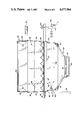
- FIG. 4 is a cross-sectional view, as viewed along line 4--4 of FIG. 3;
- FIG. 5 is an end view of the sear bar that is used to define a sear grid within the chamber
- FIG. 6 is a cross-sectional view, as viewed along line 6--6 of FIG. 4;
- FIG. 7 is an exploded view of the sear grid arrangement within the chamber
- FIG. 8 is a fragmentary top perspective view showing details of the burner assembly
- FIG. 9 is a fragmentary perspective view of the scale which supports the fuel tank.
- FIG. 10 is a cross-sectional, as viewed along line 10--10 of FIG. 9;
- FIG. 11 is a fragmentary cross-sectional view, as viewed along line 11--11 of FIG. 10.
- FIG. 12 is a side view of the pivoted working surface
- FIG. 13 is a bottom view of the view of the working surface, as viewed along line 13--13 of FIG. 12;
- FIG. 14 is a cross-sectional view, as viewed along line 14--14 of FIG. 13.
- FIG. 1 of the drawings shows a gas grill generally designated by reference numeral 20, constructed in accordance with the teachings of the present invention.
- the grill 20 consists of a portable cart 22 and a cooking vessel or chamber 24.
- the cart 22 is preferably formed from a plurality of hollow rectangular tubular members 30 (FIG. 2), including a pair of rear vertical posts 32 that define legs supported on wheels 34 at the lower end thereof.
- the second pair of vertical posts 36 extend upwardly and define the remaining two legs.
- the upper portion of the cart includes a pair of spaced parallel side members 40 which are interconnected by one or more cross-members 42.
- the side members 40 are defined by at least two end-to-end tubular members 30 that are interconnected in a unique fashion, shown in FIG. 2, without the use of any special tools or complicated fasteners.
- one tubular member 30 has a plate-like extension 44 extending from the free end and received into the adjacent open end of an adjacent tubular member 30.
- the extension has a width approximately equal to the space between the walls of tubular members 30 and is welded at one end 45 to one tubular member to hold the tubular members in end-to-end relation.
- the plate-like extension 44 has a threaded opening 46, aligned with an opening 48 in the side member, which receives a threaded fastener 50 so that the two tubular members can easily be disconnected and the cart assembly can be broken-down into smaller pieces for shipment and storage. Any number of such pieces of tubing may be utilized in assembling the cart 22 and the upper side members 40 define a generally rectangular opening for receiving the cooking vessel 24.
- the cooking vessel or housing 24 consists of a lower housing or portion 52 (FIG. 4) defining a chamber 56 and having a cover 58 secured by a hinge 60 to one upper edge of one of the sidewalls that form the chamber 56.
- the lower chamber has a burner assembly 162 located in a lower portion thereof and a sear grid arrangement 64, located above the burner assembly 62 and a cooking grid 66.
- the sear grid 64 is designed to replace the conventional heat-absorbing lava rock or equivalent materials and its supporting grid, and functions in a more acceptable manner than any material heretofore utilized.
- the sear grid 64 includes a plurality of V-shaped sear bars (FIG. 5), generally designated by reference numeral 70, and each sear bar 70 consists of a pair of inclined walls 72 that define an included angle A to produce the desired function of the sear bars.
- the included angle A is preferably less than 90°, and in the illustrated embodiment the angle is illustrated to be about 75°, but could be about 50° to about 80°.
- the inverted V-shaped sear bar 70 is preferably formed from a metal material having good heat conducting characteristics, such as cold-rolled steel, which has a porcelain enamel coating thereon.
- the two inclined walls 72 define smooth outer inclined flat surfaces that will receive dripping from food, such as meats, being cooked and cause the drippings to flow along the inclined surfaces.
- the heat from the burner assembly 62 will be trapped between the sidewalls and will quickly heat the entire sear bar to a temperature sufficient for causing a desired amount of grease received on the outer surfaces of the sidewalls 72 to vaporize and the remaining grease will pass through the sear grid 64 into a lower grease collector unit.
- the sear grid 64 is formed by five identically-constructed sear bars 70 that are supported in a predetermined position within the lower chamber 56 with small narrow spaces between adjacent bars that allow the heat to move upwardly into the upper portion of the lower chamber which supports the cooking grill or grid 66.
- the sear bars are supported within the chamber such that there is no need for any fasteners, and the sear bars may be merely dropped into position.
- the front and rear walls 80 of the housing each have an offset portion 82 that define upwardly-facing ledges within the chamber 56.
- the sear bars 70 may readily be dropped into position as shown in FIGS. 4 and 5 and the opposite ends will rest on the ledges 82.
- the ledges 82 have positioning elements 83 for defining a predetermined position between respective sear bars, as is shown in FIG. 4.
- the grill includes a second set of sear bars 70 identical to the first set, except for length, that define a second sear grid 84.
- the sear bars 70 are supported on ledges defined by offsets 86 in the sidewalls 88 of the chamber 56.
- the ledges 86 again have positioning elements 83 so that the sear bars (FIG. 6) can be dropped into position without the use of any fasteners.
- the second sear grid 84 in conjunction with the first sear grid 64, will provide more uniform heat for the cooking process than was heretofore possible in utilizing lava rock or other types of heat-absorbing materials.
- any grease or drippings off of the food being cooked will first hit the outwardly-inclined surfaces of the upper sear grid 84, which are hot and a desired amount of grease and drippings will vaporize while on the sear bars to provide the desired smoke flavoring for the food being cooked. Since each of the burner tubes of the burner assembly 62 (to be described later) is located directly below one inverted V-shaped sear bar, there is no chance of any grease being deposited directly onto the hot burners and any grease passing through the sear grids will be collected in the lower portion of chamber 56.
- the grease collector unit 90 consists of a tapered tray that has an outwardly-directed lip 92 on the peripheral edge thereof and this outwardly-directed lip is supported on inwardly-directed L-shaped brackets 94 that define slide guides for removal of the tray. It should be noted that the walls of the housing extend below and outside of brackets 94 so that any water will be directed away from the inside of the tray.
- the collector tray or unit 90 has all of its walls tapering inwardly and downwardly, as shown in FIGS. 5 and 6, so that all of the grease drippings will be directed to a central opening 96 in the center of the lowermost portion of the tray 90.
- the lower housing 52 defining chamber 56 is formed as a one-piece casting to eliminate any seams on the inner surface.
- the housing has an inwardly-directed lip 95 that defines a continuous uninterrupted surface which overlaps the peripheral edge of the grease collector unit 90 to insure that no grease escapes from the housing.
- the bracket 94 is located below the inwardly-directed lip 95, which is an integral part of the cast housing 52.
- a further smaller rectangular tray or collector 98 is located below the opening 96 and again is removably supported on a wire assembly 97.
- grease collected by the collector unit 90 will flow into the lower centermost opening 96 and into the small removable tray or cup 98, which can easily be removed and the grease discarded.
- the entire unit can be removed and easily be cleaned and reinserted.
- the small removable tray collects most of the grease received into the collector and is spaced substantially below the burner units to eliminate any possibility of ignition.
- the collector unit 90 may also be used as a broiler by providing a grill, such as a part of the two-piece grill 66.
- the burner assembly 62 is again structurally engineered such that the entire assembly can be assembled by a purchaser without the use of any special tools and in a simplified manner.
- the burner assembly 62 consists of a pair of outer burner units 110 and an intermediate burner unit 112.
- the outer burner units 110 are identical in construction and are interchangeable with each other.
- the outer burner units each consist of an elongated, preferably circular, tube 114 that has a flattened connecting portion 116 at the outer free end thereof.
- the flat connecting portion 116 has a generally U-shaped slot 118 extending from the free edge thereof and, as shown in FIG. 8, the slot is offset from the axis of the tube 114, for a purpose that will be described later.
- the lower housing 52 has a pair of corner support members 120 positioned in the corners adjacent the one end wall 80, and these corner support members 120 define an upwardly-directed supporting surface that has an upwardly-extending abutment or projection 122.
- the abutment or projection is preferably in the form of a threaded fastener or screw that has an enlarged head.
- the projection could also be formed integrally with the support member 120.
- the burner unit 110 can easily be assembled into the chamber merely by insertion of the end of the tube through an opening 124 in the opposite end wall (see FIG. 3) and the flattened portion 116 can be slid along the upper surface of the corner support member 120, with the threaded fastener 122 received into the slot 118.
- the burner unit 110 can then be secured by the fastener 122 at one end, while the opposite end rests on the edge of the opening 124 defined in the other end wall 80. Since the projection and slot are offset from the axis of the tube 114, there is no possibility of improper assembly of the two outer burner units 110.
- These burner units 110 have a row of small apertures 126 that are positioned to be directed inwardly in the assembled condition, as shown in FIG. 8, and are in a common plane with flatteded portion 116 so that any gas will be directed to the center of the lower chamber.
- a third burner unit 112 is preferably located intermediate the first and second burner units and again is easily assembled without the use of any tools.
- an open-ended connecting tube or pilot tube 130 extends between the two burner units 110 and has opposite ends received into openings 132 located in the tubes 114.
- the opposite ends of the connecting or pilot tube 130 which is substantially smaller in diameter than the tubes 114, has a plurality of apertures (not shown) so that any gas received into the first burner unit, which is then ignited, will travel through the pilot tube 130 towards the second burner unit 110.
- the first burner unit may be ignited by an electric ignitor 134 (FIG. 3), controlled by a switch 136 that is located on the control panel 138 for all of the burner units.
- the inner ends of the burner units 110 each having a control valve 140 located between a gas source tube 142 and the end of the burner tube 114.
- a control knob 144 extends from the control valve and is located above the control panel.
- the third burner unit is of slightly different construction and is positioned approximately equidistant between the outer burner units 110.
- the third burner unit 112 again consists of a generally circular tube 150 that has a flattened portion 152 on the outer free end thereof.
- the flattened portion 152 has a slot 153 (FIG. 6) for receiving the tube 130 and a small projection or plate 154 welded to the surface of the tube 130 so that the inner burner unit is accurately positioned with respect to the remainder of the burner assembly.
- the center burner tube 150 extends through an intermediate opening 154 in the other end wall 80 (FIG. 3).
- the circular tube 150 has two sets of diametrically-opposed apertures 158 (FIG. 4).
- the intermediate unit 112 again has a valve 140 and control knob 144 as shown in FIG. 6.
- the center burner unit 112 is inserted through the intermediate opening 156 and tube 130 is moved through the slot 153 in the end of the flattened end portion 152.
- One end of the tube 130 is then inserted into the opening 132 in one of the burner units 110 after it has been inserted through an opening 124 and the opposite end is then moved into the opening 132 of the second unit 110.
- the inner free ends of the burner units are interconnected by the single connecting tube 130 which defines the support for the inner end of the intermediate burner 112.
- the two outer burner units are then manipulated such that the slots 118 receive the projections 122 and the three burner units are then in the position illustrated in FIG. 8 and can be held in such position by tightening the projections 122.
- the inner end of the burner tubes rest on the lower edges of the respective openings.
- the burner assembly 62 can be ignited in sequential order, first by igniting the front burner unit 110 with the ignitor 134 by depressing of the switch 136 on control panel 138. A hole may be provided in the lower chamber for manual ignition, if desired. After the first burner unit is ignited, the second outer burner unit 110 merely needs to have gas supplied thereto and the cross-pilot tube 130 will provide the ignition for the gas in the second burner unit. Likewise, the supply of gas to the intermediate burner unit will automatically be ignited by the flames from the apertured cross-tube 130.
- burner units have been shown as linear tubes, other configurations could be used so long as the sear bars have the same configuration as the elongated burner tubes.
- the burner tubes could be U-shaped in plan view.
- the gas grill 20 of the present invention incorporates a separate burner unit 160 which is supported on the side members 40 of the cart 22 adjacent one end thereof.
- the separate burner unit 160 consists of a gas burner 162 that may normally be closed by a cover 164 hinged along one edge to the burner assembly.
- the separate burner assembly 160 rests on and is suspended between the side members 40 and can easily be moved to a different location if desired.
- the second burner unit 160 may be eliminated and a work surface may be provided.
- the working surface could be of the type shown in FIG. 1 as being a working board 170 that is supported on the side members 40 by brackets 171 (FIG. 14) adjacent the cooking vessel 24.
- a further working board 172 may also be provided which is movable between stored and usable positions respectively shown in FIGS. 3 and 1.
- the working board 172 (FIG. 12) is preferably connected along one edge by a hinge 173 to the side member 40 and is supported in the usable position, extending generally horizontally as shown in FIG. 1, by a support rod 174.
- a support rod 174 is pivotally supported on the lower surface of the board 172 and has an offset outer free end received around the leg 36. The same offset portion may be received in the other leg 36 so that the working board 172 remains in a fixed stored position when not in use.
- the working board may be formed from a plurality of slats 175 connected by cross-members 176.
- the hinge 173 includes a rod 177 connected by a bracket 178 to the working board 170.
- the rod has a flattened portion 177a on one end and is supported on a pair of brackets 179 and 179a.
- the brackets have openings 179b and one opening has a slot 179c extending to one edge for receiving the flattened portion.
- the working board can easily be removed for cleaning.
- thermometer 180 in the cover 58, which can be utilized for sensing the internal temperature of the cooking chamber or, alternatively, the internal temperature of the food or meat that is being cooked.
- thermometer 180 includes a conventional piercing portion 182 extending from an indicator dial 184. In normal operation, the portion 182 is received through an opening (not shown) in the front portion of cover 58 to be readily visible for viewing by the operator.
- the thermometer is merely removed and inserted into the food product, where the temperature is then sensed as a function of the meat temperature rather than the chamber temperature.
- the cover 56 consists of two cast end caps 190 and an insert 192 formed of non-metallic material, which are interconnected through the use of special flush-headed bolts 194.
- the end caps 190 have extensions 195 with a handle 196 secured to the extensions.
- the bolt 194 has an enlarged head 197 received with an enlarged recess 198 surrounding an opening 199 in end piece 190.
- the bolt 194 has a serrated portion 200 that provides a friction grip in the opening 199.
- the bolt 194 also has a threaded portion 202 received through an opening in the insert 192 and receives a nut 204.
- the bolt 194 can be inserted into the opening 199 and nut 204 can be used to draw the serrated portion 200 into the opening.
- the serrated portion 200 will prevent the bolt 194 from turning in the opening.
- the recessed head 197 will not protrude beyond the outer surface of the end piece 190, as shown in FIG. 3A.
- the porcelain-coated metal insert 192 has an extension 192a which extends between the handle 196 and sidewall 88 of housing 52.
- the extension acts as a heat shield to prevent the handle from overheating.
- the gas grill also incorporates a novel tank-support means for a fuel tank 210, shown in FIG. 1.
- the details of the tank-support means are shown in FIGS. 9-11.
- the tank support means is located on one end of the cart 22 between the first pair of legs 32 so that the tank is supported directly above the wheels 34.
- the tank-support means consists of a first element 212 supported on a vertical member 213 that is located between the two legs 32 and a second element 214 which is movable relative to the first element or member 212.
- the first element 212 consists of a U-shaped bracket including a base 219 and side walls 221 enclosed by a top wall 220.
- the base 219 is connected by bolts 222 to the brace 213.
- the second element 214 is pivotally supported on the first element by a pair of U-shaped members 224 each have one end pivoted on a pin 226 and each pin extends between the side walls 221 of U-shaped bracket.
- the opposite ends of the support members or bars 224 are pivotally supported on pins 230, which are carried by the second element 214.
- a biasing spring 232 has one end connected to one of the pins or rods 230 and the opposite end is connected to a threaded coupling 234 carried by the top wall 221 of the first element 212.
- the second element 214 also has a tank-support member 236 in the form of a hook 238 that is deformed from the element 214 and extends outwardly.
- the hook is adapted to be received into a slot 240 formed along the upper edge of the rim of the tank.
- a slidable clamp element 242 is held onto the element 214 by a wing nut 244 received on a threaded element 246 carried by the second element 214.
- the support means also consists of a pair of anti-friction means or rollers 250 that are rotatably supported on opposite sides of the vertical brace 213, as is shown in FIG. 1 of the drawings.
- the tank support means also incorporates an indicator arm 254 which has an inner end pivotally supported on the first element 212 and extends through a horizontal slot 256 defined in the second element 214. More specifically, as shown in FIG. 11, the inner end of arm 254 is connected to the base 219 of the U-shaped bracket and the arm extends through a vertical slot 258 in one side wall 221.
- the outer end of the arm or indicator means has a scale 260 associated therewith and the position of the arm 254 with respect to the indicator 260 indicates the amount of fuel remaining within the tank.
- the tank moves the second element 214 to pivot the arm 254 while the horizontal slot acts as a fulcrum.
- the tank is supported in cantilevered fashion along the vertical brace 213 and rests or is forced up against the anti-friction means, which allows for better movement and control of the position of the tank through its weight, which is determined by the amount of fuel in the tank.
- the spring characteristics are preferably such that the indicator arm remains in the "full" position until about 2/3 of the gas within the tank has been depleted. Thus, a more accurate indication of when the tank approaches complete depletion may be realized.
- the cart 22 may also include cross braces 270 and a reinforcing center brace 272 on which removable article-supporting units 274 may be suspended.
- the gas grill disclosed herein operates on an entirely new principal.
- the combination of tubular burners covered by inverted V-shaped sear bars and a deep removable grease collector unit with a small removable grease catcher pan at the lower end substantially eliminates the possibility of the grease in the collector unit from igniting.
- the sear bars can be quickly heated to a temperature sufficient for controlled flare-ups of the grease on the inclined surfaces to sear the meat being cooked. This is accomplished by ignition of all three tubular burners. After the meat, such as steaks, has been seared on both sides, the intermediate burner can be shut off and the sear bars' temperature will be reduced to a point where the grease thereon will not ignite, but will still vaporize to give the desired cooking flavor.
- the gas grill is designed for easy assembly without the use of any tools, and the arrangement of parts is such that minimum instructions are necessary.
Abstract
Description
Claims (30)
Priority Applications (20)
| Application Number | Priority Date | Filing Date | Title |
|---|---|---|---|
| US06/759,531 US4677964A (en) | 1985-07-26 | 1985-07-26 | Portable gas grill |
| EP90104944A EP0381250B1 (en) | 1985-07-26 | 1986-01-15 | Dual purpose thermometer in combination with a gas grill |
| AT86900949T ATE68678T1 (en) | 1985-07-26 | 1986-01-15 | PORTABLE GAS GRILL. |
| DE8686900949T DE3682191D1 (en) | 1985-07-26 | 1986-01-15 | PORTABLE GAS GRILL. |
| EP89107954A EP0336451B1 (en) | 1985-07-26 | 1986-01-15 | Portable gas grill |
| AU53910/86A AU5391086A (en) | 1985-07-26 | 1986-01-15 | Portable gas grill |
| DE8989107953T DE3687350T2 (en) | 1985-07-26 | 1986-01-15 | PORTABLE GAS GRILL. |
| EP86900949A EP0233187B1 (en) | 1985-07-26 | 1986-01-15 | Portable gas grill |
| DE8989107954T DE3687663T2 (en) | 1985-07-26 | 1986-01-15 | PORTABLE GAS GRILL. |
| EP19910100246 EP0425474A1 (en) | 1985-07-26 | 1986-01-15 | Portable gas grill |
| EP89107953A EP0332228B1 (en) | 1985-07-26 | 1986-01-15 | Portable gas grill |
| AT89107953T ATE83630T1 (en) | 1985-07-26 | 1986-01-15 | PORTABLE GAS GRILL. |
| PCT/US1986/000086 WO1987000410A1 (en) | 1985-07-26 | 1986-01-15 | Portable gas grill |
| AT90104944T ATE110244T1 (en) | 1985-07-26 | 1986-01-15 | DUAL USE THERMOMETER IN COMBINATION WITH A GAS GRILL. |
| AT89107954T ATE84953T1 (en) | 1985-07-26 | 1986-01-15 | PORTABLE GAS GRILL. |
| DE3650044T DE3650044T2 (en) | 1985-07-26 | 1986-01-15 | Thermometer with two uses in combination with a gas grill. |
| US07/069,765 US4777927A (en) | 1985-07-26 | 1987-07-06 | Barbeque kettle |
| US07/249,364 US4966125A (en) | 1985-07-26 | 1988-09-23 | Barbeque kettle |
| CA000615725A CA1300995C (en) | 1985-07-26 | 1990-05-08 | Tank scale for a gas grill |
| CA000615724A CA1300994C (en) | 1985-07-26 | 1990-05-08 | Burner assembly for a gas grill |
Applications Claiming Priority (1)
| Application Number | Priority Date | Filing Date | Title |
|---|---|---|---|
| US06/759,531 US4677964A (en) | 1985-07-26 | 1985-07-26 | Portable gas grill |
Related Child Applications (1)
| Application Number | Title | Priority Date | Filing Date |
|---|---|---|---|
| US07/069,765 Continuation-In-Part US4777927A (en) | 1985-07-26 | 1987-07-06 | Barbeque kettle |
Publications (1)
| Publication Number | Publication Date |
|---|---|
| US4677964A true US4677964A (en) | 1987-07-07 |
Family
ID=25056006
Family Applications (1)
| Application Number | Title | Priority Date | Filing Date |
|---|---|---|---|
| US06/759,531 Expired - Lifetime US4677964A (en) | 1985-07-26 | 1985-07-26 | Portable gas grill |
Country Status (1)
| Country | Link |
|---|---|
| US (1) | US4677964A (en) |
Cited By (103)
| Publication number | Priority date | Publication date | Assignee | Title |
|---|---|---|---|---|
| US4777927A (en) * | 1985-07-26 | 1988-10-18 | Weber-Stephen Products Co. | Barbeque kettle |
| US4886045A (en) * | 1989-05-02 | 1989-12-12 | The Ducane Company, Inc. | Side burner attachment for gas-fired grill |
| US4899725A (en) * | 1989-05-08 | 1990-02-13 | Barron Jr James O | Barbecue grill |
| US4944284A (en) * | 1989-09-05 | 1990-07-31 | Quin Vorney O | Portable stove |
| US5027788A (en) * | 1990-08-10 | 1991-07-02 | Weber-Stephen Products Co. | Barbecue kettle cart |
| US5031602A (en) * | 1990-08-08 | 1991-07-16 | Vick Edward H | Convertible portable cooking apparatus |
| US5050577A (en) * | 1990-05-21 | 1991-09-24 | Charmglow Industries, Inc. | Pre-assembled gas barbeque grill |
| US5070776A (en) * | 1988-08-12 | 1991-12-10 | Weber-Stephen Products Co. | Portable gas grill enhancements |
| US5076252A (en) * | 1990-08-10 | 1991-12-31 | Weber-Stephen Products Co. | Barbecue grill assembly |
| US5076256A (en) * | 1990-07-06 | 1991-12-31 | The Thermos Company, Inc. | Easily assembled barbecue grill with detachable accessory shelf and snap-in wheels |
| US5140973A (en) * | 1991-04-02 | 1992-08-25 | Grand Hall Enterprise Co., Ltd. | Barbecue grill trolley |
| US5277106A (en) * | 1990-07-02 | 1994-01-11 | The Thermos Company, Inc. | Easily assembled barbecue grill with heat distribution plate |
| US5299553A (en) * | 1992-12-01 | 1994-04-05 | Sunbeam Corporation | Kettle grill and ash-catcher assembly therefor |
| US5408985A (en) * | 1994-08-15 | 1995-04-25 | Sunbeam Corporation | Gas tank retainer |
| US5413087A (en) * | 1994-01-03 | 1995-05-09 | Khan's Enterprise Co., Ltd. | Convertible portable cooker |
| US5471916A (en) * | 1994-08-12 | 1995-12-05 | Porcelain Metals Corporation | Barbeque grill with ash sweep and integral shelf lid holder |
| US5566607A (en) * | 1995-05-11 | 1996-10-22 | Schleimer; Norman | Grill with grease deflector assembly |
| USD377734S (en) * | 1994-08-12 | 1997-02-04 | Porcelain Metals Corporation | Side shelf for a barbeque grill |
| US5617779A (en) * | 1996-08-01 | 1997-04-08 | Dutczak; Mychajlo | Barbecue grill shelf attachment |
| US5632265A (en) * | 1994-04-26 | 1997-05-27 | Modern Home Products Corp. | Grill mounting assembly |
| USD379572S (en) * | 1995-08-11 | 1997-06-03 | Porcelain Metals Corporation | Combined barbeque grill and ring shelf |
| USD380933S (en) * | 1996-01-16 | 1997-07-15 | Weber-Stephen Products Co. | Barbecue grill |
| USD381557S (en) * | 1995-08-11 | 1997-07-29 | Porcelain Metals Corporation | Combined barbeque grill and ring shelf |
| WO1998006310A1 (en) * | 1996-08-09 | 1998-02-19 | Weber-Stephen Products Co. | Barbecue cart and side work shelf assembly |
| US5765469A (en) * | 1995-05-05 | 1998-06-16 | Weber-Stephen Products Co. | Portable gas grill |
| USD404963S (en) * | 1996-08-09 | 1999-02-02 | Weber-Stephen Products Co. | Portable barbecue grill |
| US5873355A (en) * | 1995-09-01 | 1999-02-23 | Weber-Stephen Products Co. | Grill with improved portability and storage configuration |
| US5927142A (en) * | 1997-12-05 | 1999-07-27 | Henny Penny Corporation | System and method for determining drain pan fluid level |
| US6102029A (en) * | 1999-08-13 | 2000-08-15 | Weber Stephen Products Co. | Burner assembly for a gas barbecue grill |
| USD430717S (en) * | 1999-12-27 | 2000-09-05 | Weber Stephen Products Company | Barbecue grill cart |
| USD432852S (en) * | 1999-08-06 | 2000-10-31 | The Coleman Company, Inc. | Portable stove |
| USD433279S (en) * | 1998-10-07 | 2000-11-07 | Weber-Stephen Products Co. | Barbecue cooker cover |
| US6148668A (en) * | 1999-03-02 | 2000-11-21 | Weber-Stephen Products Co. | Gas grill tank scale |
| WO2001012045A1 (en) | 1999-08-13 | 2001-02-22 | Weber-Stephen Products, Co. | Dropping side shelf assembly |
| US6257130B1 (en) | 2000-08-11 | 2001-07-10 | Weber-Stephen Products Co. | Ducted smoker for barbecue grill |
| US6308616B1 (en) | 2000-08-11 | 2001-10-30 | Weber-Stephen Products Co. | Barbecue grill assembly having a work surface with slide mechanism |
| US6324998B1 (en) | 1999-08-13 | 2001-12-04 | Weber-Stephen Products Co. | End cap bar for barbeque grill cart |
| US20020020405A1 (en) * | 2000-08-11 | 2002-02-21 | Brian Coleman | Portable barbecue grill |
| US6439220B1 (en) | 2000-08-11 | 2002-08-27 | Weber-Stephen Products Co. | Barbecue grill and cart assembly |
| US6481343B1 (en) | 1998-08-25 | 2002-11-19 | Empire Comfort Systems, Inc. | Barbecue grill grate |
| USRE37988E1 (en) | 1995-09-22 | 2003-02-18 | Newell Operating Company | Cookware top |
| WO2003024289A1 (en) * | 2001-09-12 | 2003-03-27 | Stefan Barth | Barbeque fuel tank system |
| US6619600B1 (en) | 2000-08-11 | 2003-09-16 | Weber-Stephen Products Co. | Barbecue gas grill having a welded frame assembly |
| USD481588S1 (en) | 2002-09-13 | 2003-11-04 | Weber-Stephen Products Co. | Wheel for outdoor cooking device |
| USD481907S1 (en) | 2002-09-13 | 2003-11-11 | Weber-Stephen Products Co. | Wheel for outdoor cooking device |
| USD481908S1 (en) | 2002-09-13 | 2003-11-11 | Weber-Stephen Products Co. | Wheel for outdoor cooking device |
| WO2003096857A1 (en) | 2002-05-15 | 2003-11-27 | Weber-Stephen Products Co. | Removable gas burner unit for barbecue grill |
| US20030230299A1 (en) * | 2002-05-15 | 2003-12-18 | Bruno Adrian A. | Barbecue grill assembly |
| USD483992S1 (en) | 2002-09-13 | 2003-12-23 | Weber-Stephen Products Co. | Wheel for outdoor cooking device |
| US20040072116A1 (en) * | 1999-08-10 | 2004-04-15 | The Coleman Company, Inc. | Heat distribution system |
| US20040112364A1 (en) * | 2002-12-13 | 2004-06-17 | Mark Johnson | Barbecue grill and support frame assembly |
| US20040112362A1 (en) * | 2002-12-13 | 2004-06-17 | Bruno Adrian A. | Cooking grate with grease control structures |
| WO2004054416A1 (en) | 2002-12-13 | 2004-07-01 | Weber-Stephen Products Co. | Heat distributing cooking grate with grease control structure for a barcecue grill |
| US6805113B2 (en) | 2001-08-10 | 2004-10-19 | Weber-Stephen Products Co. | Support frame barbecue grill assembly |
| US20040216621A1 (en) * | 2002-12-13 | 2004-11-04 | Schlosser Erich J. | Heat distributing cooking grate with grease control structure for a barbecue grill |
| USD498975S1 (en) | 2002-09-13 | 2004-11-30 | Weber-Stephen Products Co. | Wheel for outdoor cooking device |
| US20050229917A1 (en) * | 2004-03-29 | 2005-10-20 | Profitt Mark T | Gas grill |
| US20050252504A1 (en) * | 2004-05-11 | 2005-11-17 | The Coleman Company, Inc. | Collapsible cooking stand |
| US20050263009A1 (en) * | 2004-05-26 | 2005-12-01 | Peter Woodland | Sear bar for grill |
| US6978671B1 (en) * | 2001-09-10 | 2005-12-27 | Daniel Meggs | Gas tank gauge |
| US20060112948A1 (en) * | 2004-11-05 | 2006-06-01 | Ducate John Sr | Warming apparatus |
| US20060147865A1 (en) * | 2005-01-05 | 2006-07-06 | Charles Czajka | Cooking range burner head assembly |
| US20060147861A1 (en) * | 2005-01-05 | 2006-07-06 | Charles Czajka | Gas circuit and pilot light system for cooking range |
| US20060144253A1 (en) * | 2005-01-05 | 2006-07-06 | Charles Czajka | Cooking range assembly and monolithic drip pan |
| US7163011B2 (en) | 2001-10-05 | 2007-01-16 | Eastman Outdoors, Inc. | Outdoor gas grill with auxiliary burner unit, and method of using same |
| US20070028912A1 (en) * | 2005-08-03 | 2007-02-08 | Gagas John M | Modular Portable Grill |
| US20070103884A1 (en) * | 2005-11-09 | 2007-05-10 | Popowich David J | Illuminated dial |
| US20070103907A1 (en) * | 2005-11-09 | 2007-05-10 | Popowich David J | Retractable light assembly for a barbeque |
| US7222619B2 (en) | 2004-08-12 | 2007-05-29 | Original Ideas, Inc | Storable shelves for a barbecue |
| US20070137499A1 (en) * | 2005-11-23 | 2007-06-21 | Sunbeam Products, Inc. | Cooking appliance with removable cooking surface |
| US20070169768A1 (en) * | 2006-01-26 | 2007-07-26 | Kiosky Chung | Barbeque grill having foldable device |
| US20070221202A1 (en) * | 2006-03-27 | 2007-09-27 | Bruno Adrian A | Grease Drip Pan and Gas Tank Blocker for a Barbecue Grill |
| US20070266863A1 (en) * | 2006-05-16 | 2007-11-22 | Frigo Michael J | Smoker attachment for a barbecue grill |
| US20080038681A1 (en) * | 2006-08-11 | 2008-02-14 | I-Hua Huang | Display controller for gas burners |
| US20090126716A1 (en) * | 2007-11-21 | 2009-05-21 | Geoglobal Partners, Llc | U-shaped burner for grill |
| US20090223384A1 (en) * | 2008-03-06 | 2009-09-10 | Meco Corporation | Grill with baffle arrangement to make cooking temperature more uniform |
| US20090291402A1 (en) * | 2006-07-07 | 2009-11-26 | Eun Seong Cho | Flame structure of gas burner |
| US20090314285A1 (en) * | 2008-06-20 | 2009-12-24 | Marsh Brian E | Cooking device and associated methods |
| US7640929B2 (en) | 2002-12-13 | 2010-01-05 | Weber-Stephen Products Co. | Barbecue grill cooking chamber with grease control structures |
| US20100139643A1 (en) * | 2008-12-09 | 2010-06-10 | Whirlpool Corporation | User activated grease tray drain |
| US20100139642A1 (en) * | 2008-12-09 | 2010-06-10 | Whirlpool Corporation | Multi-compartment grease tray |
| US20100154776A1 (en) * | 2005-01-05 | 2010-06-24 | Charles Czajka | Cooking range burner head assembly |
| US20110067685A1 (en) * | 2009-09-23 | 2011-03-24 | Myers Robert L | Gas-Fueled Food Cooker with a Sealed Heating Conduit |
| US20110083659A1 (en) * | 2009-10-08 | 2011-04-14 | James Grasso | Grill handle with heat shield |
| US20110284546A1 (en) * | 2010-05-24 | 2011-11-24 | Cathal Gordon | Multipurpose cooking stove container |
| US20120037143A1 (en) * | 2010-08-10 | 2012-02-16 | Kiosky Chung | Space-extendable baking oven |
| USD660646S1 (en) | 2005-07-30 | 2012-05-29 | A&J Manufacturing, LLC | Pair of lids for a dual grill |
| US8381712B1 (en) * | 2004-07-31 | 2013-02-26 | II John Lee SIMMS | Simultaneous multiple cooking mode barbecue grill |
| US20140021199A1 (en) * | 2012-07-18 | 2014-01-23 | Olanrewaju Ari Adeniyi | Handle with a heat sink |
| US8776778B1 (en) * | 2009-12-03 | 2014-07-15 | Mario Brown | Tailgate barbeque grill |
| US8919706B2 (en) | 2012-05-03 | 2014-12-30 | Weber-Stephen Products Llc | Gas manifold bracket for gas grill |
| US20160037969A1 (en) * | 2014-08-05 | 2016-02-11 | John Robin Renner | Flare-up Preventing Grill |
| US20160316966A1 (en) * | 2014-10-31 | 2016-11-03 | Khosro David ILLULIAN | Modular cooking apparatus |
| US9504354B1 (en) * | 2013-08-23 | 2016-11-29 | Salvador Ficarra | Combination barbecue grill and smoker apparatus |
| GR1008982B (en) * | 2015-12-23 | 2017-03-14 | Μανουσος Γεωργιου Κλαπακης | Outdoor roaster potentially operating with a ac and dc multi-voltage skewer's rotor |
| US20170167723A1 (en) * | 2015-12-11 | 2017-06-15 | Randy Rummel | Cross-Flame Burner System |
| AU2016225826B2 (en) * | 2014-12-18 | 2017-08-31 | Weber-Stephen Products Llc | Fuel efficient grill for direct and indirect cooking |
| US10070754B2 (en) | 2014-12-18 | 2018-09-11 | Weber-Stephen Products Llc | Fuel efficient grill for direct and indirect cooking |
| US10519703B1 (en) * | 2018-07-10 | 2019-12-31 | Weber-Stephen Products Llc | Grill hinge |
| US10694845B2 (en) * | 2016-07-08 | 2020-06-30 | Mill Brothers Landscape & Nursery, Inc. | Grill insert enclosure |
| USD914430S1 (en) | 2020-01-10 | 2021-03-30 | Weber-Stephen Products Llc | Grill |
| WO2022192848A1 (en) * | 2021-03-08 | 2022-09-15 | Lifetime Products, Inc. | Drip tray for a cooking device |
| USD1013439S1 (en) | 2021-07-21 | 2024-02-06 | Weber-Stephen Products Llc | Grill |
Citations (26)
| Publication number | Priority date | Publication date | Assignee | Title |
|---|---|---|---|---|
| NL38189C (en) * | ||||
| US411576A (en) * | 1889-09-24 | Joseph n | ||
| US1133850A (en) * | 1914-02-27 | 1915-03-30 | Eugene Garraux | Broiler. |
| US1224157A (en) * | 1916-08-31 | 1917-05-01 | Detroit Stove Works | Gas-burner. |
| GB143701A (en) * | 1919-05-07 | 1920-06-03 | Henry Augustus Wall | Improvements in or relating to gas cookers |
| US1548185A (en) * | 1924-06-21 | 1925-08-04 | Carr William | Portable stove |
| US1954476A (en) * | 1932-10-05 | 1934-04-10 | Gloekler John Edward | Gas burner |
| US1964805A (en) * | 1933-02-13 | 1934-07-03 | Swartzbaugh Mfg Company | Food conveyer construction |
| FR832111A (en) * | 1937-01-15 | 1938-09-22 | Gas heater | |
| US2196280A (en) * | 1938-10-22 | 1940-04-09 | Thornhill | Scoop scale |
| US2304140A (en) * | 1940-01-20 | 1942-12-08 | Bergholm John | Gas griddle |
| US2447925A (en) * | 1945-10-02 | 1948-08-24 | Vorbusch George | Gas burner supporting stand |
| US2541528A (en) * | 1945-06-26 | 1951-02-13 | Gen Bronze Corp | Stove grill |
| US2740517A (en) * | 1955-06-02 | 1956-04-03 | Century Display Mfg Company In | Tote tray |
| US2842044A (en) * | 1957-07-31 | 1958-07-08 | Kirk Regina | Barbecue cooker |
| US2881695A (en) * | 1955-05-09 | 1959-04-14 | Pietro Carmelo V Di | Broiler |
| US3418921A (en) * | 1966-04-25 | 1968-12-31 | Vulcan Hart Corp | Broiler |
| US3474724A (en) * | 1968-04-26 | 1969-10-28 | Jenn Air Corp | Capsule for use in a stove |
| US3545908A (en) * | 1968-10-16 | 1970-12-08 | Trane Co | Gas burner |
| US3567065A (en) * | 1969-03-06 | 1971-03-02 | Interlake Steel Corp | Hinge structure for a cooking-grill construction |
| US3859978A (en) * | 1973-09-17 | 1975-01-14 | Locke Stove Company | Cooking device |
| US4233890A (en) * | 1979-07-16 | 1980-11-18 | Jansen Robert A | Outdoor Bar-B-Q smoker and grill |
| US4245505A (en) * | 1979-07-30 | 1981-01-20 | Turco Manufacturing Co. | Indicator of amount of liquefied gas in bottle |
| US4321857A (en) * | 1980-04-08 | 1982-03-30 | Best Willie H | Infrared gas grill |
| US4413515A (en) * | 1981-08-14 | 1983-11-08 | Dart Industries Inc. | Barbecue fuel level gauge |
| US4485972A (en) * | 1981-10-15 | 1984-12-04 | Marquette Tool And Die Company | Burner for cooking grills |
-
1985
- 1985-07-26 US US06/759,531 patent/US4677964A/en not_active Expired - Lifetime
Patent Citations (26)
| Publication number | Priority date | Publication date | Assignee | Title |
|---|---|---|---|---|
| NL38189C (en) * | ||||
| US411576A (en) * | 1889-09-24 | Joseph n | ||
| US1133850A (en) * | 1914-02-27 | 1915-03-30 | Eugene Garraux | Broiler. |
| US1224157A (en) * | 1916-08-31 | 1917-05-01 | Detroit Stove Works | Gas-burner. |
| GB143701A (en) * | 1919-05-07 | 1920-06-03 | Henry Augustus Wall | Improvements in or relating to gas cookers |
| US1548185A (en) * | 1924-06-21 | 1925-08-04 | Carr William | Portable stove |
| US1954476A (en) * | 1932-10-05 | 1934-04-10 | Gloekler John Edward | Gas burner |
| US1964805A (en) * | 1933-02-13 | 1934-07-03 | Swartzbaugh Mfg Company | Food conveyer construction |
| FR832111A (en) * | 1937-01-15 | 1938-09-22 | Gas heater | |
| US2196280A (en) * | 1938-10-22 | 1940-04-09 | Thornhill | Scoop scale |
| US2304140A (en) * | 1940-01-20 | 1942-12-08 | Bergholm John | Gas griddle |
| US2541528A (en) * | 1945-06-26 | 1951-02-13 | Gen Bronze Corp | Stove grill |
| US2447925A (en) * | 1945-10-02 | 1948-08-24 | Vorbusch George | Gas burner supporting stand |
| US2881695A (en) * | 1955-05-09 | 1959-04-14 | Pietro Carmelo V Di | Broiler |
| US2740517A (en) * | 1955-06-02 | 1956-04-03 | Century Display Mfg Company In | Tote tray |
| US2842044A (en) * | 1957-07-31 | 1958-07-08 | Kirk Regina | Barbecue cooker |
| US3418921A (en) * | 1966-04-25 | 1968-12-31 | Vulcan Hart Corp | Broiler |
| US3474724A (en) * | 1968-04-26 | 1969-10-28 | Jenn Air Corp | Capsule for use in a stove |
| US3545908A (en) * | 1968-10-16 | 1970-12-08 | Trane Co | Gas burner |
| US3567065A (en) * | 1969-03-06 | 1971-03-02 | Interlake Steel Corp | Hinge structure for a cooking-grill construction |
| US3859978A (en) * | 1973-09-17 | 1975-01-14 | Locke Stove Company | Cooking device |
| US4233890A (en) * | 1979-07-16 | 1980-11-18 | Jansen Robert A | Outdoor Bar-B-Q smoker and grill |
| US4245505A (en) * | 1979-07-30 | 1981-01-20 | Turco Manufacturing Co. | Indicator of amount of liquefied gas in bottle |
| US4321857A (en) * | 1980-04-08 | 1982-03-30 | Best Willie H | Infrared gas grill |
| US4413515A (en) * | 1981-08-14 | 1983-11-08 | Dart Industries Inc. | Barbecue fuel level gauge |
| US4485972A (en) * | 1981-10-15 | 1984-12-04 | Marquette Tool And Die Company | Burner for cooking grills |
Cited By (153)
| Publication number | Priority date | Publication date | Assignee | Title |
|---|---|---|---|---|
| US4777927A (en) * | 1985-07-26 | 1988-10-18 | Weber-Stephen Products Co. | Barbeque kettle |
| US5070776A (en) * | 1988-08-12 | 1991-12-10 | Weber-Stephen Products Co. | Portable gas grill enhancements |
| US4886045A (en) * | 1989-05-02 | 1989-12-12 | The Ducane Company, Inc. | Side burner attachment for gas-fired grill |
| US4899725A (en) * | 1989-05-08 | 1990-02-13 | Barron Jr James O | Barbecue grill |
| US4944284A (en) * | 1989-09-05 | 1990-07-31 | Quin Vorney O | Portable stove |
| US5050577A (en) * | 1990-05-21 | 1991-09-24 | Charmglow Industries, Inc. | Pre-assembled gas barbeque grill |
| US5277106A (en) * | 1990-07-02 | 1994-01-11 | The Thermos Company, Inc. | Easily assembled barbecue grill with heat distribution plate |
| US5076256A (en) * | 1990-07-06 | 1991-12-31 | The Thermos Company, Inc. | Easily assembled barbecue grill with detachable accessory shelf and snap-in wheels |
| US5031602A (en) * | 1990-08-08 | 1991-07-16 | Vick Edward H | Convertible portable cooking apparatus |
| US5076252A (en) * | 1990-08-10 | 1991-12-31 | Weber-Stephen Products Co. | Barbecue grill assembly |
| WO1992002165A1 (en) * | 1990-08-10 | 1992-02-20 | Weber-Stephen Products Co. | Barbecue grill assembly |
| EP0542896A1 (en) * | 1990-08-10 | 1993-05-26 | Weber-Stephen Products Co. | Barbecue grill assembly |
| EP0542896A4 (en) * | 1990-08-10 | 1993-10-06 | Weber-Stephen Products Co. | Barbecue grill assembly |
| AU643830B2 (en) * | 1990-08-10 | 1993-11-25 | Weber-Stephen Products Co. | Barbecue grill assembly |
| US5027788A (en) * | 1990-08-10 | 1991-07-02 | Weber-Stephen Products Co. | Barbecue kettle cart |
| US5140973A (en) * | 1991-04-02 | 1992-08-25 | Grand Hall Enterprise Co., Ltd. | Barbecue grill trolley |
| US5299553A (en) * | 1992-12-01 | 1994-04-05 | Sunbeam Corporation | Kettle grill and ash-catcher assembly therefor |
| US5413087A (en) * | 1994-01-03 | 1995-05-09 | Khan's Enterprise Co., Ltd. | Convertible portable cooker |
| US5632265A (en) * | 1994-04-26 | 1997-05-27 | Modern Home Products Corp. | Grill mounting assembly |
| US5471916A (en) * | 1994-08-12 | 1995-12-05 | Porcelain Metals Corporation | Barbeque grill with ash sweep and integral shelf lid holder |
| USD377734S (en) * | 1994-08-12 | 1997-02-04 | Porcelain Metals Corporation | Side shelf for a barbeque grill |
| US5408985A (en) * | 1994-08-15 | 1995-04-25 | Sunbeam Corporation | Gas tank retainer |
| US5765469A (en) * | 1995-05-05 | 1998-06-16 | Weber-Stephen Products Co. | Portable gas grill |
| US5934184A (en) * | 1995-05-05 | 1999-08-10 | Weber-Stephen Products Co. | Portable gas grill |
| US5566607A (en) * | 1995-05-11 | 1996-10-22 | Schleimer; Norman | Grill with grease deflector assembly |
| USD379572S (en) * | 1995-08-11 | 1997-06-03 | Porcelain Metals Corporation | Combined barbeque grill and ring shelf |
| USD381557S (en) * | 1995-08-11 | 1997-07-29 | Porcelain Metals Corporation | Combined barbeque grill and ring shelf |
| US6131562A (en) * | 1995-09-01 | 2000-10-17 | Weber-Stephen Products Co. | Grill with improved gas manifold |
| US5873355A (en) * | 1995-09-01 | 1999-02-23 | Weber-Stephen Products Co. | Grill with improved portability and storage configuration |
| USRE37988E1 (en) | 1995-09-22 | 2003-02-18 | Newell Operating Company | Cookware top |
| USD380933S (en) * | 1996-01-16 | 1997-07-15 | Weber-Stephen Products Co. | Barbecue grill |
| US5617779A (en) * | 1996-08-01 | 1997-04-08 | Dutczak; Mychajlo | Barbecue grill shelf attachment |
| WO1998006310A1 (en) * | 1996-08-09 | 1998-02-19 | Weber-Stephen Products Co. | Barbecue cart and side work shelf assembly |
| USD404963S (en) * | 1996-08-09 | 1999-02-02 | Weber-Stephen Products Co. | Portable barbecue grill |
| US5941229A (en) * | 1996-08-09 | 1999-08-24 | Weber Stephen Products Co. | Barbecue cart and side work shelf assembly |
| US5927142A (en) * | 1997-12-05 | 1999-07-27 | Henny Penny Corporation | System and method for determining drain pan fluid level |
| US6481343B1 (en) | 1998-08-25 | 2002-11-19 | Empire Comfort Systems, Inc. | Barbecue grill grate |
| USD433279S (en) * | 1998-10-07 | 2000-11-07 | Weber-Stephen Products Co. | Barbecue cooker cover |
| US6148668A (en) * | 1999-03-02 | 2000-11-21 | Weber-Stephen Products Co. | Gas grill tank scale |
| USD432852S (en) * | 1999-08-06 | 2000-10-31 | The Coleman Company, Inc. | Portable stove |
| US20040072116A1 (en) * | 1999-08-10 | 2004-04-15 | The Coleman Company, Inc. | Heat distribution system |
| US6913458B2 (en) | 1999-08-10 | 2005-07-05 | The Coleman Company, Inc. | Heat distribution system |
| WO2001012045A1 (en) | 1999-08-13 | 2001-02-22 | Weber-Stephen Products, Co. | Dropping side shelf assembly |
| US6324998B1 (en) | 1999-08-13 | 2001-12-04 | Weber-Stephen Products Co. | End cap bar for barbeque grill cart |
| US6102029A (en) * | 1999-08-13 | 2000-08-15 | Weber Stephen Products Co. | Burner assembly for a gas barbecue grill |
| US6354548B1 (en) | 1999-08-13 | 2002-03-12 | Weber-Stephen Products Company | Dropping side shelf assembly |
| USD430717S (en) * | 1999-12-27 | 2000-09-05 | Weber Stephen Products Company | Barbecue grill cart |
| WO2002013667A2 (en) | 2000-08-11 | 2002-02-21 | Weber-Stephen Products Co. | Barbecue grill assembly having a work surface with slide mechanism |
| US20020020405A1 (en) * | 2000-08-11 | 2002-02-21 | Brian Coleman | Portable barbecue grill |
| US6508165B2 (en) | 2000-08-11 | 2003-01-21 | Weber-Stephen Products Co. | Barbecue grill assembly having a work surface with slide mechanism |
| US6257130B1 (en) | 2000-08-11 | 2001-07-10 | Weber-Stephen Products Co. | Ducted smoker for barbecue grill |
| US6951213B2 (en) * | 2000-08-11 | 2005-10-04 | W.C. Bradley Company | Portable barbecue grill |
| US6619600B1 (en) | 2000-08-11 | 2003-09-16 | Weber-Stephen Products Co. | Barbecue gas grill having a welded frame assembly |
| US6308616B1 (en) | 2000-08-11 | 2001-10-30 | Weber-Stephen Products Co. | Barbecue grill assembly having a work surface with slide mechanism |
| US6439220B1 (en) | 2000-08-11 | 2002-08-27 | Weber-Stephen Products Co. | Barbecue grill and cart assembly |
| US20090084376A1 (en) * | 2000-12-13 | 2009-04-02 | Mark Johnson | Barbecue cooking apparatus with base having folding shelves |
| US20090095277A1 (en) * | 2000-12-13 | 2009-04-16 | Mark Johnson | Barbecue cooking apparatus with folding shelves |
| US7438071B2 (en) | 2000-12-13 | 2008-10-21 | Weber-Stephen Products, Co. | Barbecue grill with folding shelves |
| US7762249B2 (en) | 2000-12-13 | 2010-07-27 | Weber-Stephen Products, Co. | Barbecue grill with frame and mounting assembly |
| US8161958B2 (en) | 2000-12-13 | 2012-04-24 | Weber-Stephen Products Co. | Barbecue cooking apparatus with base having folding shelves |
| US8851060B2 (en) | 2000-12-13 | 2014-10-07 | Weber-Stephen Products Co. | Barbecue cooking apparatus with folding shelves |
| US6805113B2 (en) | 2001-08-10 | 2004-10-19 | Weber-Stephen Products Co. | Support frame barbecue grill assembly |
| US6978671B1 (en) * | 2001-09-10 | 2005-12-27 | Daniel Meggs | Gas tank gauge |
| WO2003024289A1 (en) * | 2001-09-12 | 2003-03-27 | Stefan Barth | Barbeque fuel tank system |
| US7163011B2 (en) | 2001-10-05 | 2007-01-16 | Eastman Outdoors, Inc. | Outdoor gas grill with auxiliary burner unit, and method of using same |
| US6705307B2 (en) | 2002-05-15 | 2004-03-16 | Weber-Stephens Product Co. | Removable gas burner unit for barbecue grill |
| US20030230299A1 (en) * | 2002-05-15 | 2003-12-18 | Bruno Adrian A. | Barbecue grill assembly |
| WO2003096857A1 (en) | 2002-05-15 | 2003-11-27 | Weber-Stephen Products Co. | Removable gas burner unit for barbecue grill |
| US6925998B2 (en) | 2002-05-15 | 2005-08-09 | Weber-Stephen Products Co. | Barbecue grill assembly |
| USD483992S1 (en) | 2002-09-13 | 2003-12-23 | Weber-Stephen Products Co. | Wheel for outdoor cooking device |
| USD498975S1 (en) | 2002-09-13 | 2004-11-30 | Weber-Stephen Products Co. | Wheel for outdoor cooking device |
| USD481908S1 (en) | 2002-09-13 | 2003-11-11 | Weber-Stephen Products Co. | Wheel for outdoor cooking device |
| USD481907S1 (en) | 2002-09-13 | 2003-11-11 | Weber-Stephen Products Co. | Wheel for outdoor cooking device |
| USD481588S1 (en) | 2002-09-13 | 2003-11-04 | Weber-Stephen Products Co. | Wheel for outdoor cooking device |
| US6976485B2 (en) | 2002-12-13 | 2005-12-20 | Weber-Stephen Products Co. | Barbecue grill and support frame assembly |
| US20040112364A1 (en) * | 2002-12-13 | 2004-06-17 | Mark Johnson | Barbecue grill and support frame assembly |
| US7640929B2 (en) | 2002-12-13 | 2010-01-05 | Weber-Stephen Products Co. | Barbecue grill cooking chamber with grease control structures |
| US20060048765A1 (en) * | 2002-12-13 | 2006-03-09 | Bruno Adrian A | Cooking grate |
| WO2004054416A1 (en) | 2002-12-13 | 2004-07-01 | Weber-Stephen Products Co. | Heat distributing cooking grate with grease control structure for a barcecue grill |
| US7810484B2 (en) | 2002-12-13 | 2010-10-12 | Weber-Stephen Products Co. | Heat distributing cooking grate with grease control structure for a barbecue grill |
| US20040216621A1 (en) * | 2002-12-13 | 2004-11-04 | Schlosser Erich J. | Heat distributing cooking grate with grease control structure for a barbecue grill |
| US6910476B2 (en) | 2002-12-13 | 2005-06-28 | Weber-Stephen Products Co. | Barbecue grill and support frame assembly |
| US7073429B2 (en) | 2002-12-13 | 2006-07-11 | Weber-Stephen Products Co. | Cooking grate with grease control structures |
| US20050166767A1 (en) * | 2002-12-13 | 2005-08-04 | Mark Johnson | Barbecue grill and support frame assembly |
| EP1958553A1 (en) | 2002-12-13 | 2008-08-20 | Weber-Stephen Products Co. | Heat distributing cooking grate with grease control structure for a barbecue grill |
| US7373875B2 (en) | 2002-12-13 | 2008-05-20 | Weber-Stephen Products Co. | Cooking grate |
| US20040112362A1 (en) * | 2002-12-13 | 2004-06-17 | Bruno Adrian A. | Cooking grate with grease control structures |
| US20050229917A1 (en) * | 2004-03-29 | 2005-10-20 | Profitt Mark T | Gas grill |
| US20050252504A1 (en) * | 2004-05-11 | 2005-11-17 | The Coleman Company, Inc. | Collapsible cooking stand |
| US20050263009A1 (en) * | 2004-05-26 | 2005-12-01 | Peter Woodland | Sear bar for grill |
| US7478589B2 (en) | 2004-05-26 | 2009-01-20 | Woodland Home Products Pty Limited | Sear bar for grill |
| US8381712B1 (en) * | 2004-07-31 | 2013-02-26 | II John Lee SIMMS | Simultaneous multiple cooking mode barbecue grill |
| US7222619B2 (en) | 2004-08-12 | 2007-05-29 | Original Ideas, Inc | Storable shelves for a barbecue |
| US20060112948A1 (en) * | 2004-11-05 | 2006-06-01 | Ducate John Sr | Warming apparatus |
| US7363923B2 (en) | 2005-01-05 | 2008-04-29 | Illinois Tool Works Inc. | cooking range assembly and monolithic drip pan |
| US7811082B2 (en) | 2005-01-05 | 2010-10-12 | Premark Feg, Llc | Gas circuit and pilot light system for cooking range |
| US20060147865A1 (en) * | 2005-01-05 | 2006-07-06 | Charles Czajka | Cooking range burner head assembly |
| US20060147861A1 (en) * | 2005-01-05 | 2006-07-06 | Charles Czajka | Gas circuit and pilot light system for cooking range |
| US20100154776A1 (en) * | 2005-01-05 | 2010-06-24 | Charles Czajka | Cooking range burner head assembly |
| US20060144253A1 (en) * | 2005-01-05 | 2006-07-06 | Charles Czajka | Cooking range assembly and monolithic drip pan |
| USD660646S1 (en) | 2005-07-30 | 2012-05-29 | A&J Manufacturing, LLC | Pair of lids for a dual grill |
| US20070028912A1 (en) * | 2005-08-03 | 2007-02-08 | Gagas John M | Modular Portable Grill |
| US7798139B2 (en) * | 2005-08-03 | 2010-09-21 | Western Industries, Inc. | Modular portable grill |
| US20070103884A1 (en) * | 2005-11-09 | 2007-05-10 | Popowich David J | Illuminated dial |
| US20070103907A1 (en) * | 2005-11-09 | 2007-05-10 | Popowich David J | Retractable light assembly for a barbeque |
| US7222979B1 (en) | 2005-11-09 | 2007-05-29 | Cfm Corporation | Illuminated dial |
| US7872213B2 (en) | 2005-11-23 | 2011-01-18 | Sunbeam Products, Inc. | Cooking appliance with removable cooking surface |
| US20070137499A1 (en) * | 2005-11-23 | 2007-06-21 | Sunbeam Products, Inc. | Cooking appliance with removable cooking surface |
| US20070169768A1 (en) * | 2006-01-26 | 2007-07-26 | Kiosky Chung | Barbeque grill having foldable device |
| US8347874B2 (en) * | 2006-03-27 | 2013-01-08 | Weber-Stephen Products Co. | Grease drip pan and gas tank blocker for a barbecue grill |
| US20070221202A1 (en) * | 2006-03-27 | 2007-09-27 | Bruno Adrian A | Grease Drip Pan and Gas Tank Blocker for a Barbecue Grill |
| US20070266863A1 (en) * | 2006-05-16 | 2007-11-22 | Frigo Michael J | Smoker attachment for a barbecue grill |
| US7866256B2 (en) | 2006-05-16 | 2011-01-11 | Frigo Michael J | Smoker attachment for a barbecue grill |
| US20090291402A1 (en) * | 2006-07-07 | 2009-11-26 | Eun Seong Cho | Flame structure of gas burner |
| US20080038681A1 (en) * | 2006-08-11 | 2008-02-14 | I-Hua Huang | Display controller for gas burners |
| US20090126716A1 (en) * | 2007-11-21 | 2009-05-21 | Geoglobal Partners, Llc | U-shaped burner for grill |
| US20090223384A1 (en) * | 2008-03-06 | 2009-09-10 | Meco Corporation | Grill with baffle arrangement to make cooking temperature more uniform |
| US20090314285A1 (en) * | 2008-06-20 | 2009-12-24 | Marsh Brian E | Cooking device and associated methods |
| US8261731B2 (en) * | 2008-06-20 | 2012-09-11 | Marsh Brian E | Cooking device and associated methods |
| US8176843B2 (en) * | 2008-12-09 | 2012-05-15 | Whirlpool Corporation | Multi-compartment grease tray |
| US8109263B2 (en) * | 2008-12-09 | 2012-02-07 | Whirlpool Corporation | User activated grease tray drain |
| US20100139642A1 (en) * | 2008-12-09 | 2010-06-10 | Whirlpool Corporation | Multi-compartment grease tray |
| US20100139643A1 (en) * | 2008-12-09 | 2010-06-10 | Whirlpool Corporation | User activated grease tray drain |
| US20110067685A1 (en) * | 2009-09-23 | 2011-03-24 | Myers Robert L | Gas-Fueled Food Cooker with a Sealed Heating Conduit |
| CN102068209A (en) * | 2009-10-08 | 2011-05-25 | 韦伯-斯蒂芬产品公司 | Grill handle with heat shield |
| US20110083659A1 (en) * | 2009-10-08 | 2011-04-14 | James Grasso | Grill handle with heat shield |
| US8316836B2 (en) * | 2009-10-08 | 2012-11-27 | Weber-Stephen Products Co., Inc. | Grill handle with heat shield |
| CN102068209B (en) * | 2009-10-08 | 2014-03-12 | 韦伯-斯蒂芬产品公司 | Grill handle with heat shield |
| US8776778B1 (en) * | 2009-12-03 | 2014-07-15 | Mario Brown | Tailgate barbeque grill |
| US8640906B2 (en) * | 2010-05-24 | 2014-02-04 | Cathal Patrick Gordon | Multipurpose cooking stove container |
| US20110284546A1 (en) * | 2010-05-24 | 2011-11-24 | Cathal Gordon | Multipurpose cooking stove container |
| US20120037143A1 (en) * | 2010-08-10 | 2012-02-16 | Kiosky Chung | Space-extendable baking oven |
| US8919706B2 (en) | 2012-05-03 | 2014-12-30 | Weber-Stephen Products Llc | Gas manifold bracket for gas grill |
| US20140021199A1 (en) * | 2012-07-18 | 2014-01-23 | Olanrewaju Ari Adeniyi | Handle with a heat sink |
| US9788688B1 (en) * | 2013-08-23 | 2017-10-17 | Salvador Ficarra | Combination barbecue grill and smoker apparatus |
| US9504354B1 (en) * | 2013-08-23 | 2016-11-29 | Salvador Ficarra | Combination barbecue grill and smoker apparatus |
| US20160037969A1 (en) * | 2014-08-05 | 2016-02-11 | John Robin Renner | Flare-up Preventing Grill |
| US20160316966A1 (en) * | 2014-10-31 | 2016-11-03 | Khosro David ILLULIAN | Modular cooking apparatus |
| US10758084B2 (en) | 2014-12-18 | 2020-09-01 | Weber-Stephen Products Llc | Fuel efficient grill for direct and indirect cooking |
| US10722074B2 (en) | 2014-12-18 | 2020-07-28 | Weber-Stephen Products Llc | Fuel efficient grill for direct and indirect cooking |
| AU2016225826B2 (en) * | 2014-12-18 | 2017-08-31 | Weber-Stephen Products Llc | Fuel efficient grill for direct and indirect cooking |
| US10070754B2 (en) | 2014-12-18 | 2018-09-11 | Weber-Stephen Products Llc | Fuel efficient grill for direct and indirect cooking |
| US10070755B2 (en) | 2014-12-18 | 2018-09-11 | Weber-Stephen Products Llc | Fuel efficient grill for direct and indirect cooking |
| US10159380B2 (en) * | 2015-12-11 | 2018-12-25 | Randy Rummel | Cross-flame burner system |
| US20170167723A1 (en) * | 2015-12-11 | 2017-06-15 | Randy Rummel | Cross-Flame Burner System |
| GR1008982B (en) * | 2015-12-23 | 2017-03-14 | Μανουσος Γεωργιου Κλαπακης | Outdoor roaster potentially operating with a ac and dc multi-voltage skewer's rotor |
| US10694845B2 (en) * | 2016-07-08 | 2020-06-30 | Mill Brothers Landscape & Nursery, Inc. | Grill insert enclosure |
| US10519703B1 (en) * | 2018-07-10 | 2019-12-31 | Weber-Stephen Products Llc | Grill hinge |
| US11808072B2 (en) | 2018-07-10 | 2023-11-07 | Weber-Stephen Products Llc | Grill hinge |
| USD914430S1 (en) | 2020-01-10 | 2021-03-30 | Weber-Stephen Products Llc | Grill |
| USD971674S1 (en) | 2020-01-10 | 2022-12-06 | Weber-Stephen Products Llc | Grill |
| WO2022192848A1 (en) * | 2021-03-08 | 2022-09-15 | Lifetime Products, Inc. | Drip tray for a cooking device |
| USD1013439S1 (en) | 2021-07-21 | 2024-02-06 | Weber-Stephen Products Llc | Grill |
Similar Documents
| Publication | Publication Date | Title |
|---|---|---|
| US4677964A (en) | Portable gas grill | |
| CA1300994C (en) | Burner assembly for a gas grill | |
| US4727853A (en) | Sear grid for portable grill | |
| US5934183A (en) | Portable gas grill | |
| US8261732B2 (en) | Cooking grill | |
| AU609849B2 (en) | Barbecue kettle | |
| US4321857A (en) | Infrared gas grill | |
| US4886045A (en) | Side burner attachment for gas-fired grill | |
| US5536518A (en) | Convertible grill/rotisserie barbecue | |
| US5974954A (en) | Barbecue grill grate | |
| EP3203886B1 (en) | Dual cooking mode bbq grill | |
| US7905225B2 (en) | Cooking grill | |
| US4966125A (en) | Barbeque kettle | |
| CN104814675B (en) | Cooking device | |
| US20150265099A1 (en) | Combination Gas and Charcoal Grill | |
| US3520290A (en) | Grate-supporting bracket for outdoor grill | |
| US20120247448A1 (en) | Modular Outdoor Cooking System | |
| EP1405012A2 (en) | Portable barbecue grill | |
| AU579258B2 (en) | Portable gas barbecue | |
| US6523461B1 (en) | Charcoal tray and cooking rack for dual fuel barbeque grill | |
| CA1279540C (en) | Portable gas grill | |
| KR100712054B1 (en) | Meat roaster of moving type |
Legal Events
| Date | Code | Title | Description |
|---|---|---|---|
| AS | Assignment |
Owner name: WEBER-STEPHEN PRODUCTS, CO., A CORP. OF IL. Free format text: ASSIGNMENT OF ASSIGNORS INTEREST.;ASSIGNORS:SIMPKINS, RONALD W.;PESTKA, DONALD E.;REEL/FRAME:004450/0948 Effective date: 19850717 Owner name: WEBER-STEPHEN PRODUCTS CO., A CORP. OF IL. Free format text: ASSIGNMENT OF ASSIGNORS INTEREST.;ASSIGNORS:STEPHEN JAMES C.;LEJA ANDRZEJ;BEECHER JOHN III;REEL/FRAME:004450/0949 Effective date: 19850717 Owner name: WEBER-STEPEN PRODUCTS, A CORP. OF IL. Free format text: ASSIGNMENT OF ASSIGNORS INTEREST.;ASSIGNORS:LOHMEYER, CHARLES W.;SCHLOSSER, ERICH J.;REEL/FRAME:004450/0947 Effective date: 19850904 |
|
| STCF | Information on status: patent grant |
Free format text: PATENTED CASE |
|
| CC | Certificate of correction | ||
| FPAY | Fee payment |
Year of fee payment: 4 |
|
| FEPP | Fee payment procedure |
Free format text: PAYOR NUMBER ASSIGNED (ORIGINAL EVENT CODE: ASPN); ENTITY STATUS OF PATENT OWNER: LARGE ENTITY Free format text: PAT HLDR NO LONGER CLAIMS SMALL ENT STAT AS SMALL BUSINESS (ORIGINAL EVENT CODE: LSM2); ENTITY STATUS OF PATENT OWNER: LARGE ENTITY |
|
| FPAY | Fee payment |
Year of fee payment: 8 |
|
| FPAY | Fee payment |
Year of fee payment: 12 |
|
| RR | Request for reexamination filed |
Effective date: 19990208 |