US4681556A - Assembly of composite shaft and yoke member of a Hookes universal joint - Google Patents
Assembly of composite shaft and yoke member of a Hookes universal joint Download PDFInfo
- Publication number
- US4681556A US4681556A US06/668,727 US66872784A US4681556A US 4681556 A US4681556 A US 4681556A US 66872784 A US66872784 A US 66872784A US 4681556 A US4681556 A US 4681556A
- Authority
- US
- United States
- Prior art keywords
- yoke member
- tubular portions
- fibres
- around
- spigot portion
- Prior art date
- Legal status (The legal status is an assumption and is not a legal conclusion. Google has not performed a legal analysis and makes no representation as to the accuracy of the status listed.)
- Expired - Fee Related
Links
Images

Classifications
-
- B—PERFORMING OPERATIONS; TRANSPORTING
- B60—VEHICLES IN GENERAL
- B60K—ARRANGEMENT OR MOUNTING OF PROPULSION UNITS OR OF TRANSMISSIONS IN VEHICLES; ARRANGEMENT OR MOUNTING OF PLURAL DIVERSE PRIME-MOVERS IN VEHICLES; AUXILIARY DRIVES FOR VEHICLES; INSTRUMENTATION OR DASHBOARDS FOR VEHICLES; ARRANGEMENTS IN CONNECTION WITH COOLING, AIR INTAKE, GAS EXHAUST OR FUEL SUPPLY OF PROPULSION UNITS IN VEHICLES
- B60K17/00—Arrangement or mounting of transmissions in vehicles
- B60K17/22—Arrangement or mounting of transmissions in vehicles characterised by arrangement, location, or type of main drive shafting, e.g. cardan shaft
-
- F—MECHANICAL ENGINEERING; LIGHTING; HEATING; WEAPONS; BLASTING
- F16—ENGINEERING ELEMENTS AND UNITS; GENERAL MEASURES FOR PRODUCING AND MAINTAINING EFFECTIVE FUNCTIONING OF MACHINES OR INSTALLATIONS; THERMAL INSULATION IN GENERAL
- F16C—SHAFTS; FLEXIBLE SHAFTS; ELEMENTS OR CRANKSHAFT MECHANISMS; ROTARY BODIES OTHER THAN GEARING ELEMENTS; BEARINGS
- F16C3/00—Shafts; Axles; Cranks; Eccentrics
- F16C3/02—Shafts; Axles
- F16C3/026—Shafts made of fibre reinforced resin
-
- F—MECHANICAL ENGINEERING; LIGHTING; HEATING; WEAPONS; BLASTING
- F16—ENGINEERING ELEMENTS AND UNITS; GENERAL MEASURES FOR PRODUCING AND MAINTAINING EFFECTIVE FUNCTIONING OF MACHINES OR INSTALLATIONS; THERMAL INSULATION IN GENERAL
- F16D—COUPLINGS FOR TRANSMITTING ROTATION; CLUTCHES; BRAKES
- F16D3/00—Yielding couplings, i.e. with means permitting movement between the connected parts during the drive
- F16D3/16—Universal joints in which flexibility is produced by means of pivots or sliding or rolling connecting parts
- F16D3/26—Hooke's joints or other joints with an equivalent intermediate member to which each coupling part is pivotally or slidably connected
- F16D3/38—Hooke's joints or other joints with an equivalent intermediate member to which each coupling part is pivotally or slidably connected with a single intermediate member with trunnions or bearings arranged on two axes perpendicular to one another
- F16D3/382—Hooke's joints or other joints with an equivalent intermediate member to which each coupling part is pivotally or slidably connected with a single intermediate member with trunnions or bearings arranged on two axes perpendicular to one another constructional details of other than the intermediate member
- F16D3/387—Fork construction; Mounting of fork on shaft; Adapting shaft for mounting of fork
-
- F—MECHANICAL ENGINEERING; LIGHTING; HEATING; WEAPONS; BLASTING
- F16—ENGINEERING ELEMENTS AND UNITS; GENERAL MEASURES FOR PRODUCING AND MAINTAINING EFFECTIVE FUNCTIONING OF MACHINES OR INSTALLATIONS; THERMAL INSULATION IN GENERAL
- F16C—SHAFTS; FLEXIBLE SHAFTS; ELEMENTS OR CRANKSHAFT MECHANISMS; ROTARY BODIES OTHER THAN GEARING ELEMENTS; BEARINGS
- F16C2326/00—Articles relating to transporting
- F16C2326/01—Parts of vehicles in general
- F16C2326/06—Drive shafts
-
- F—MECHANICAL ENGINEERING; LIGHTING; HEATING; WEAPONS; BLASTING
- F16—ENGINEERING ELEMENTS AND UNITS; GENERAL MEASURES FOR PRODUCING AND MAINTAINING EFFECTIVE FUNCTIONING OF MACHINES OR INSTALLATIONS; THERMAL INSULATION IN GENERAL
- F16C—SHAFTS; FLEXIBLE SHAFTS; ELEMENTS OR CRANKSHAFT MECHANISMS; ROTARY BODIES OTHER THAN GEARING ELEMENTS; BEARINGS
- F16C2361/00—Apparatus or articles in engineering in general
- F16C2361/41—Couplings
Definitions
- This invention relates to shafts made of composite, fibre reinforced resin, material. More particularly the invention relates to an assembly of such a shaft and a yoke member of a Hookes universal joint.
- Such shafts may be used, for example, as drive shafts extending between engine and rear axle in conventional rear wheel drive motor vehicles.
- the yoke member of a Hookes universal joint can be secured to a composite shaft by use of an adhesive.
- the yoke member may be incorporated in the structure of the shaft during manufacture thereof by winding the fibres over a mandrel which is subsequently removed, the yoke member being positioned on the mandrel and the fibres being wound thereover.
- Such constructional methods require the use of yoke members which are of massive construction with a tubular spigot portion over which the fibres are wound, the yokes typically being steel forgings. Such construction is heavy and expensive.
- a composite, fibre reinforced resin, shaft and a yoke member of a Hookes universal joint comprising a sheet metal element with a spigot portion extending axially of the shaft and tubular portions extending transversely thereof and adapted to form or receive bearing elements of the joint, the shaft including fibres wound around said spigot portion and fibres extending around at least part of the circumference of said tubular portions.
- Winding the fibres on the yoke member in such a way that they reinforce the tubular portions thereof enables the yoke member to be entirely of relatively thin sheet metal such as steel or an aluminium alloy.
- the extending of the fibres around the tubular portions also provides a high degree of axial security and torque transmitting ability between the yoke member and shaft, compared with that which would obtain if the fibres were wound around the spigot portion only of the yoke member.
- the tubular portions may be integral with the rest of the yoke member. Alternatively they may be separate sheet metal components.
- the yoke member may be manufactured from flat sheet metal which is formed to a generally tubular configuration, or may be manufactured from tube stock.
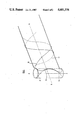
- FIG. 1 is a section through an assembly according to the invention.
- FIG. 2 shows diagrammatically one method of fibre winding according to the invention.
- the assembly illustrated in FIG. 1 comprises a sheet metal Hookes joint yoke member with a spigot portion 10 extending axially of the shaft and two tubular portions 11 extending transversely thereof.
- the portions 11 are provided internally with grooves 12 for receiving circlips by which bearing cups are retained in the portions 11, for supporting opposed trunnions of the cross member of a Hookes joint.
- the yoke member has diametrically opposed cutaways 13 which accommodate the other trunnions of the cross member and other yoke of the joint when assembled, and the boundary of this cut-away is flanged at 14, to provide a guide for fibre winding and to assist rigidity.
- the spigot portion 10 of the yoke member has layers 15 of resin impregnated fibres wound thereon. Typically such fibres will include successive layers wound at different helix angles. Fibres are also wound at 16 on the tubular portions 11 of the yoke member to extend at least partly around the circumference thereof. The windings of such fibres may be continuous with those fibres 15 wound helically on the spigot portion 10 and forming the shaft itself.
- FIG. 2 One possible configuration of winding such fibres is shown in FIG. 2.
- the axis of the shaft and spigot portion 10 of the joint yoke member is shown at B--B and that of the tubular portions 11 at A--A.
- One fibre winding is shown extending helically around the spigot portion at 20, circumferentially at 21 around one of the tubular portions of the yoke member, and then returning at 22 along the spigot portion helically in the opposite sense and direction.
- Other windings would extend around the opposite tubular portion of the yoke member, and thus the shaft would be progressively built up.
- Some fibres may extend circumferentially of one of the tubular portions of the yoke member, as shown at 23 in FIG.
- the yoke member may be formed by appropriate pressing operations from flat sheet metal or tubular stock.
- the tubular portions 11 may be integral with the remainder of the yoke member, or may be separate tubular components secured thereto by welding or mechanical fixing.
- the yoke member would be placed on a mandrel and fibres, impregnated with a suitable resin, wound thereon to form the shaft and secure the yoke member therein. Subsequent to curing of the resin, the mandrel would be removed. Machines for winding fibres in predetermined configurations on mandrels are well known, and need not be described in detail herein.
- the above description relates to a yoke member which, as is usual for automotive drive shaft application, receives bearing cups which in turn receive opposed journals of the cross member of the Hookes joint.
- the invention is applicable to Hookes joints for other applications in which different bearing constructions are utilized.
- journals of the cross member may be received directly in the tubular portions of the yoke member, provided the cross member is appropriately dimensioned to enable it to be assembled in the yoke.
- Such a construction may be suitable for light duty, e.g. a steering shaft.
Abstract
Description
Claims (6)
Applications Claiming Priority (2)
| Application Number | Priority Date | Filing Date | Title |
|---|---|---|---|
| GB8306543 | 1983-03-09 | ||
| GB838306543A GB8306543D0 (en) | 1983-03-09 | 1983-03-09 | Composite shafts |
Publications (1)
| Publication Number | Publication Date |
|---|---|
| US4681556A true US4681556A (en) | 1987-07-21 |
Family
ID=10539281
Family Applications (1)
| Application Number | Title | Priority Date | Filing Date |
|---|---|---|---|
| US06/668,727 Expired - Fee Related US4681556A (en) | 1983-03-09 | 1984-03-08 | Assembly of composite shaft and yoke member of a Hookes universal joint |
Country Status (5)
| Country | Link |
|---|---|
| US (1) | US4681556A (en) |
| EP (2) | EP0138896B1 (en) |
| DE (1) | DE3463828D1 (en) |
| GB (2) | GB8306543D0 (en) |
| WO (1) | WO1984003544A1 (en) |
Cited By (16)
| Publication number | Priority date | Publication date | Assignee | Title |
|---|---|---|---|---|
| US4786759A (en) * | 1986-11-14 | 1988-11-22 | Les Cables De Lyon | Articulated cable head for submarine links |
| US5009628A (en) * | 1988-03-28 | 1991-04-23 | Glaenzer-Spicer | Body having a composite structure for a transmission joint and its method of production |
| US5314382A (en) * | 1991-09-24 | 1994-05-24 | Geislinger & Co. Schwingungstechnik Gesellschaft M.B.H. | Torque-transmitting coupling member |
| US5397272A (en) * | 1993-02-08 | 1995-03-14 | Pressure Technology, Inc. | Braided composite shaft with yoke member |
| US5605507A (en) * | 1993-06-02 | 1997-02-25 | Institut Francais Du Petrole | Mechanical linking device made of wound fiber-reinforced resin manufacturing process |
| US5683300A (en) * | 1994-02-17 | 1997-11-04 | Kabushiki Kaisha Toyoda Jidoshokki Seisakusho | Drive shaft made of fiber reinforced composite material and method of manufacturing the same |
| US5724715A (en) * | 1996-07-02 | 1998-03-10 | Addax, Inc. | Composite flange for drive shafts |
| US5946977A (en) * | 1995-11-28 | 1999-09-07 | Katayama Kogyo Co., Ltd. | Collapsible steering column |
| US6586110B1 (en) | 2000-07-07 | 2003-07-01 | Delphi Technologies, Inc. | Contoured metal structural members and methods for making the same |
| US6821638B2 (en) | 2000-07-07 | 2004-11-23 | Delphi Technologies, Inc. | Shaped contoured crushable structural members and methods for making the same |
| EP1508711A1 (en) * | 2003-08-22 | 2005-02-23 | American Axle & Manufacturing, Inc. | Overmolded yoke assembly |
| US6949282B2 (en) | 2000-07-07 | 2005-09-27 | Delphi Technologies, Inc. | Contoured crushable composite structural members and methods for making the same |
| US7427237B2 (en) * | 2002-01-03 | 2008-09-23 | Burkett Jerald S | Load sharing composite shaft |
| EP2476924A1 (en) | 2011-01-14 | 2012-07-18 | SKF Aerospace France | Shaft for transmitting rotational movements and/or forces and method of manufacturing the same. |
| US8850823B2 (en) | 2009-12-29 | 2014-10-07 | Rolls-Royce North American Technologies, Inc. | Integrated aero-engine flowpath structure |
| EP3381668A1 (en) * | 2017-03-31 | 2018-10-03 | Crompton Technology Group Limited | Composite shaft |
Families Citing this family (9)
| Publication number | Priority date | Publication date | Assignee | Title |
|---|---|---|---|---|
| EP0267980B1 (en) * | 1982-09-30 | 1991-10-23 | The Boeing Company | Method of fabricating a rotor hub of composite material |
| DE3608754A1 (en) * | 1986-03-15 | 1987-09-24 | Uni Cardan Ag | DRIVE SHAFT, ESPECIALLY DRIVE SHAFT, MADE OF FIBER REINFORCED PLASTIC, AND METHOD AND DEVICE FOR PRODUCING THE DRIVE SHAFT |
| US5591084A (en) * | 1990-10-22 | 1997-01-07 | Gkn Glaenzer Spicer | Transmission joint body portion having an envelope with interior peripheral surface portions extending opposite to and contoured substantially the same as opposite rear surfaces of bearing tracks |
| FR2668222B1 (en) * | 1990-10-22 | 1995-06-09 | Glaenzer Spicer Sa | TYPE TRANSMISSION JOINT BODY HAVING A CONNECTING FLANGE. |
| GB2339265A (en) * | 1998-07-08 | 2000-01-19 | Flight Refueling Ltd | Rotary power transmission shaft and manufacture thereof |
| EP1108602A1 (en) * | 1999-12-13 | 2001-06-20 | Pankl R&D GmbH | Shaft with integrated flange |
| CN103596792B (en) * | 2011-04-15 | 2016-09-21 | Gkn动力传动系统北美有限公司 | Tubular axle combined for metal interface |
| DE102012211840A1 (en) * | 2012-07-06 | 2014-01-09 | Wethje Beteiligungs GmbH | Fiber-reinforced drive shaft and eyelet winding method for manufacturing |
| DE102014016776A1 (en) | 2014-11-13 | 2016-05-19 | Kurt-Schwabe-Institut für Mess- und Sensortechnik e.V. Meinsberg | Indicator electrode and method for its production |
Citations (11)
| Publication number | Priority date | Publication date | Assignee | Title |
|---|---|---|---|---|
| SU261892A1 (en) * | В. В. Косклов, А. С. Токарев, В. Б. Суханов , Н. Е. нзин | METHOD FOR ASSEMBLY OF CARDAN HINGE | ||
| US2067283A (en) * | 1934-08-01 | 1937-01-12 | Joseph E Padgett | Joint member and method of making same |
| US3651661A (en) * | 1970-02-02 | 1972-03-28 | United Aircraft Corp | Composite shaft with integral end flange |
| US4106797A (en) * | 1976-05-07 | 1978-08-15 | Fiber Glass Systems, Inc. | Reinforced fitting construction |
| DE2851292A1 (en) * | 1977-11-25 | 1979-05-31 | Shakespeare Co | DRIVE SHAFT CONSTRUCTION AND METHOD FOR THE PRODUCTION THEREOF |
| GB2040395A (en) * | 1979-01-11 | 1980-08-28 | Ehrenberg K | Joint half for a universal joint |
| US4248062A (en) * | 1979-10-05 | 1981-02-03 | Shakespeare Company | Drive shaft assembly and method for making same |
| US4275122A (en) * | 1978-07-17 | 1981-06-23 | Gkn Transmissions Limited | Shaft and universal joint member assembly |
| JPS5744536A (en) * | 1980-08-28 | 1982-03-13 | Mazda Motor Corp | Manufacture method of car propeller shaft |
| US4325174A (en) * | 1977-04-28 | 1982-04-20 | Union Carbide Corporation | Composite drive shafts |
| US4345625A (en) * | 1977-09-02 | 1982-08-24 | Sekisui Kagaku Kogyo Kabushiki Kaisha | Pipe joints of reinforced resin and process for their molding |
Family Cites Families (1)
| Publication number | Priority date | Publication date | Assignee | Title |
|---|---|---|---|---|
| DE2951629C2 (en) * | 1979-12-21 | 1985-03-14 | Felten & Guilleaume Energietechnik GmbH, 5000 Köln | Drive shaft made of fiber-reinforced plastic, with a lost mandrel and tightly wound end pieces |
-
1983
- 1983-03-09 GB GB838306543A patent/GB8306543D0/en active Pending
-
1984
- 1984-03-08 EP EP84901201A patent/EP0138896B1/en not_active Expired
- 1984-03-08 GB GB08427535A patent/GB2146739B/en not_active Expired
- 1984-03-08 EP EP84301539A patent/EP0122033A1/en active Pending
- 1984-03-08 WO PCT/GB1984/000073 patent/WO1984003544A1/en active IP Right Grant
- 1984-03-08 DE DE8484901201T patent/DE3463828D1/en not_active Expired
- 1984-03-08 US US06/668,727 patent/US4681556A/en not_active Expired - Fee Related
Patent Citations (11)
| Publication number | Priority date | Publication date | Assignee | Title |
|---|---|---|---|---|
| SU261892A1 (en) * | В. В. Косклов, А. С. Токарев, В. Б. Суханов , Н. Е. нзин | METHOD FOR ASSEMBLY OF CARDAN HINGE | ||
| US2067283A (en) * | 1934-08-01 | 1937-01-12 | Joseph E Padgett | Joint member and method of making same |
| US3651661A (en) * | 1970-02-02 | 1972-03-28 | United Aircraft Corp | Composite shaft with integral end flange |
| US4106797A (en) * | 1976-05-07 | 1978-08-15 | Fiber Glass Systems, Inc. | Reinforced fitting construction |
| US4325174A (en) * | 1977-04-28 | 1982-04-20 | Union Carbide Corporation | Composite drive shafts |
| US4345625A (en) * | 1977-09-02 | 1982-08-24 | Sekisui Kagaku Kogyo Kabushiki Kaisha | Pipe joints of reinforced resin and process for their molding |
| DE2851292A1 (en) * | 1977-11-25 | 1979-05-31 | Shakespeare Co | DRIVE SHAFT CONSTRUCTION AND METHOD FOR THE PRODUCTION THEREOF |
| US4275122A (en) * | 1978-07-17 | 1981-06-23 | Gkn Transmissions Limited | Shaft and universal joint member assembly |
| GB2040395A (en) * | 1979-01-11 | 1980-08-28 | Ehrenberg K | Joint half for a universal joint |
| US4248062A (en) * | 1979-10-05 | 1981-02-03 | Shakespeare Company | Drive shaft assembly and method for making same |
| JPS5744536A (en) * | 1980-08-28 | 1982-03-13 | Mazda Motor Corp | Manufacture method of car propeller shaft |
Cited By (23)
| Publication number | Priority date | Publication date | Assignee | Title |
|---|---|---|---|---|
| US4786759A (en) * | 1986-11-14 | 1988-11-22 | Les Cables De Lyon | Articulated cable head for submarine links |
| US5009628A (en) * | 1988-03-28 | 1991-04-23 | Glaenzer-Spicer | Body having a composite structure for a transmission joint and its method of production |
| US5314382A (en) * | 1991-09-24 | 1994-05-24 | Geislinger & Co. Schwingungstechnik Gesellschaft M.B.H. | Torque-transmitting coupling member |
| US5397272A (en) * | 1993-02-08 | 1995-03-14 | Pressure Technology, Inc. | Braided composite shaft with yoke member |
| US5605507A (en) * | 1993-06-02 | 1997-02-25 | Institut Francais Du Petrole | Mechanical linking device made of wound fiber-reinforced resin manufacturing process |
| US5683300A (en) * | 1994-02-17 | 1997-11-04 | Kabushiki Kaisha Toyoda Jidoshokki Seisakusho | Drive shaft made of fiber reinforced composite material and method of manufacturing the same |
| EP0668446B1 (en) * | 1994-02-17 | 2002-06-26 | Kabushiki Kaisha Toyota Jidoshokki | Method of manufacturing of a drive shaft made of fiber reinforced composite material |
| US5946977A (en) * | 1995-11-28 | 1999-09-07 | Katayama Kogyo Co., Ltd. | Collapsible steering column |
| US5724715A (en) * | 1996-07-02 | 1998-03-10 | Addax, Inc. | Composite flange for drive shafts |
| US6821638B2 (en) | 2000-07-07 | 2004-11-23 | Delphi Technologies, Inc. | Shaped contoured crushable structural members and methods for making the same |
| US6586110B1 (en) | 2000-07-07 | 2003-07-01 | Delphi Technologies, Inc. | Contoured metal structural members and methods for making the same |
| US20050089707A1 (en) * | 2000-07-07 | 2005-04-28 | Delphi Technologies, Inc. | Shaped contoured crushable structural members and methods for making the same |
| US6893733B2 (en) | 2000-07-07 | 2005-05-17 | Delphi Technologies, Inc. | Modified contoured crushable structural members and methods for making the same |
| US6949282B2 (en) | 2000-07-07 | 2005-09-27 | Delphi Technologies, Inc. | Contoured crushable composite structural members and methods for making the same |
| US7427237B2 (en) * | 2002-01-03 | 2008-09-23 | Burkett Jerald S | Load sharing composite shaft |
| EP1508711A1 (en) * | 2003-08-22 | 2005-02-23 | American Axle & Manufacturing, Inc. | Overmolded yoke assembly |
| US8850823B2 (en) | 2009-12-29 | 2014-10-07 | Rolls-Royce North American Technologies, Inc. | Integrated aero-engine flowpath structure |
| FR2970533A1 (en) * | 2011-01-14 | 2012-07-20 | Skf Aerospace France | SHAFT FOR TRANSMISSION OF MOVEMENTS AND / OR ROTATION EFFORTS, AND METHOD FOR MANUFACTURING SUCH TREE |
| US8690692B2 (en) | 2011-01-14 | 2014-04-08 | Skf Aerospace France | Transmission shaft for transmitting rotational movements and/or forces, and method for manufacturing said shaft |
| EP2476924A1 (en) | 2011-01-14 | 2012-07-18 | SKF Aerospace France | Shaft for transmitting rotational movements and/or forces and method of manufacturing the same. |
| EP3381668A1 (en) * | 2017-03-31 | 2018-10-03 | Crompton Technology Group Limited | Composite shaft |
| US11137018B2 (en) | 2017-03-31 | 2021-10-05 | Crompton Technology Group Limited | Composite shaft |
| US20210404511A1 (en) * | 2017-03-31 | 2021-12-30 | Crompton Technology Group Limited | Composite shaft |
Also Published As
| Publication number | Publication date |
|---|---|
| GB8306543D0 (en) | 1983-04-13 |
| EP0138896A1 (en) | 1985-05-02 |
| DE3463828D1 (en) | 1987-06-25 |
| GB2146739B (en) | 1986-10-08 |
| EP0138896B1 (en) | 1987-05-20 |
| GB2146739A (en) | 1985-04-24 |
| GB8427535D0 (en) | 1984-12-05 |
| WO1984003544A1 (en) | 1984-09-13 |
| EP0122033A1 (en) | 1984-10-17 |
Similar Documents
| Publication | Publication Date | Title |
|---|---|---|
| US4681556A (en) | Assembly of composite shaft and yoke member of a Hookes universal joint | |
| US4932924A (en) | Torque transmitting assembly | |
| US4663819A (en) | Method of mounting a metal yoke to a composite tube | |
| US4238539A (en) | Fiber reinforced composite shaft with metallic connector sleeves mounted by a knurl interlock | |
| US4421497A (en) | Fiber-reinforced drive shaft | |
| US4358284A (en) | Fiber-reinforced driveshaft | |
| US4211589A (en) | Shaft and universal joint assembly | |
| US4952195A (en) | Graphite drive shaft assembly | |
| US4275122A (en) | Shaft and universal joint member assembly | |
| US4664644A (en) | Fiber reinforced plastic drive shaft and method of manufacturing thereof | |
| US4540385A (en) | Drive shaft assembly | |
| US4380443A (en) | Fiber-reinforced drive shaft | |
| CA1068501A (en) | Joint structure and method of joining | |
| US5637042A (en) | Drive line assembly with reducing tube yoke | |
| EP0685659A1 (en) | Drive shaft tube and end fitting assembly and method of manufacturing same | |
| US6368225B1 (en) | Axially collapsible driveshaft assembly and method of manufacturing same | |
| GB2051303A (en) | Fibre-reinforced composite shaft with metallic connector sleeves | |
| US6367680B1 (en) | Component for vehicular driveshaft assembly and method of manufacturing same | |
| US7181846B2 (en) | Method of manufacturing a combined driveshaft tube and yoke assembly | |
| JPH06213228A (en) | Mechanical tubular element such as transmission shaft of motor vehicle | |
| GB2127938A (en) | Method of forming a composite drive shaft tube | |
| US20050028341A1 (en) | Method of manufacturing a combined driveshaft tube and yoke assembly | |
| US5611135A (en) | Method of making a tube yoke for drive line assembly | |
| GB2119479A (en) | Yoke in a universal joint | |
| US4568314A (en) | Universal joint shaft assembly |
Legal Events
| Date | Code | Title | Description |
|---|---|---|---|
| AS | Assignment |
Owner name: BRD COMPANY LIMITED, P.O. BOX 2, ALDRIDGE, WALSALL Free format text: ASSIGNMENT OF ASSIGNORS INTEREST.;ASSIGNOR:PALMER, BERTRAM J.;REEL/FRAME:004334/0652 Effective date: 19840925 Owner name: BRD COMPANY LIMITED,ENGLAND Free format text: ASSIGNMENT OF ASSIGNORS INTEREST;ASSIGNOR:PALMER, BERTRAM J.;REEL/FRAME:004334/0652 Effective date: 19840925 |
|
| FEPP | Fee payment procedure |
Free format text: PAYOR NUMBER ASSIGNED (ORIGINAL EVENT CODE: ASPN); ENTITY STATUS OF PATENT OWNER: LARGE ENTITY |
|
| REMI | Maintenance fee reminder mailed | ||
| LAPS | Lapse for failure to pay maintenance fees | ||
| STCH | Information on status: patent discontinuation |
Free format text: PATENT EXPIRED DUE TO NONPAYMENT OF MAINTENANCE FEES UNDER 37 CFR 1.362 |
|
| FP | Lapsed due to failure to pay maintenance fee |
Effective date: 19910721 |