US4688675A - Nesting box with reduced lid flares - Google Patents
Nesting box with reduced lid flares Download PDFInfo
- Publication number
- US4688675A US4688675A US06/706,318 US70631885A US4688675A US 4688675 A US4688675 A US 4688675A US 70631885 A US70631885 A US 70631885A US 4688675 A US4688675 A US 4688675A
- Authority
- US
- United States
- Prior art keywords
- lid
- lids
- flange
- tote box
- box
- Prior art date
- Legal status (The legal status is an assumption and is not a legal conclusion. Google has not performed a legal analysis and makes no representation as to the accuracy of the status listed.)
- Ceased
Links
Images


Classifications
-
- B—PERFORMING OPERATIONS; TRANSPORTING
- B65—CONVEYING; PACKING; STORING; HANDLING THIN OR FILAMENTARY MATERIAL
- B65D—CONTAINERS FOR STORAGE OR TRANSPORT OF ARTICLES OR MATERIALS, e.g. BAGS, BARRELS, BOTTLES, BOXES, CANS, CARTONS, CRATES, DRUMS, JARS, TANKS, HOPPERS, FORWARDING CONTAINERS; ACCESSORIES, CLOSURES, OR FITTINGS THEREFOR; PACKAGING ELEMENTS; PACKAGES
- B65D43/00—Lids or covers for rigid or semi-rigid containers
- B65D43/14—Non-removable lids or covers
- B65D43/16—Non-removable lids or covers hinged for upward or downward movement
- B65D43/163—Non-removable lids or covers hinged for upward or downward movement the container and the lid being made separately
- B65D43/164—Non-removable lids or covers hinged for upward or downward movement the container and the lid being made separately and connected by interfitting hinge elements integrally with the container and the lid formed respectively
- B65D43/165—Non-removable lids or covers hinged for upward or downward movement the container and the lid being made separately and connected by interfitting hinge elements integrally with the container and the lid formed respectively these elements being assembled by a separate pin-like member
-
- B—PERFORMING OPERATIONS; TRANSPORTING
- B65—CONVEYING; PACKING; STORING; HANDLING THIN OR FILAMENTARY MATERIAL
- B65D—CONTAINERS FOR STORAGE OR TRANSPORT OF ARTICLES OR MATERIALS, e.g. BAGS, BARRELS, BOTTLES, BOXES, CANS, CARTONS, CRATES, DRUMS, JARS, TANKS, HOPPERS, FORWARDING CONTAINERS; ACCESSORIES, CLOSURES, OR FITTINGS THEREFOR; PACKAGING ELEMENTS; PACKAGES
- B65D21/00—Nestable, stackable or joinable containers; Containers of variable capacity
- B65D21/02—Containers specially shaped, or provided with fittings or attachments, to facilitate nesting, stacking, or joining together
- B65D21/06—Containers specially shaped, or provided with fittings or attachments, to facilitate nesting, stacking, or joining together with movable parts adapted to be placed in alternative positions for nesting the containers when empty and for stacking them when full
- B65D21/064—Containers specially shaped, or provided with fittings or attachments, to facilitate nesting, stacking, or joining together with movable parts adapted to be placed in alternative positions for nesting the containers when empty and for stacking them when full the movable parts being an attached or integral cover made of one or two pieces
-
- B—PERFORMING OPERATIONS; TRANSPORTING
- B65—CONVEYING; PACKING; STORING; HANDLING THIN OR FILAMENTARY MATERIAL
- B65D—CONTAINERS FOR STORAGE OR TRANSPORT OF ARTICLES OR MATERIALS, e.g. BAGS, BARRELS, BOTTLES, BOXES, CANS, CARTONS, CRATES, DRUMS, JARS, TANKS, HOPPERS, FORWARDING CONTAINERS; ACCESSORIES, CLOSURES, OR FITTINGS THEREFOR; PACKAGING ELEMENTS; PACKAGES
- B65D2251/00—Details relating to container closures
- B65D2251/10—Details of hinged closures
- B65D2251/1083—Closures formed of several sections hinged to the container or base
Definitions
- Tote boxes are general purpose containers, particularly for distribution of goods or their temporary storage. They are called upon to contain a wide variety of goods as they are shipped from a distribution point to a destination, for example, from a warehouse to retail outlets, from a manufacturer to a user, or within a manufacturing plant itself, for example.
- the present invention relates to containers that may be nested within like containers so that their attached lids may shingle with the adjacent lids of the other containers, particularly for tote boxes and most particularly for tote boxes having two lids.
- the invention is particularly related to such boxes or containers that are molded, for example of a synthetic resin or plastic, so that the side and end walls are tapered towards the bottom to facilitate nesting of empty containers, wherein one or more lids are hinged respectively to the containers so that the lids may be swing generally 270° from their closed position to a position wherein they shingle with respect to each other when the containers are nested, and which lids have reinforcing ribs and/or one or more flanges on each side to overlap the adjacent side wall in the closed position.
- the latter patent employs attached lids and an elaborate hinge structure so that the lids may lay flat against the sides of the boxes or be shingled when a plurality of boxes are nested to address the problem of lid flare, so that a considerable number of receptacles may be compactly nested with relatively little addition to the transverse dimension of the box.
- Lid flare is designated as the increase in horizontal dimension, on one side of the box, as measured perpendicular to the attached lid hinge axis, as caused by nesting of a plurality of such boxes and corresponding shingling of their attached lids.
- Lid flare has been a well known problem in the art with many attempts made at reducing it.
- FIGS. 2 and 3 of the Weickart U.S. Pat. No. 3,383,009, issued May 14, 1968 clearly shows the advantages of reduced height in nesting containers for the return trip, and also clearly shows the problems of lid flare in increasing the horizontal dimension by nesting with shingled attached lids.
- a particularly advantageous tote box was developed by the assignee of the present invention, and involved two attached lids, with ribbing for increasing the rigidity of the lids and lid sides having a side skirt flange, preferably together with an inboard flange forming channel-shaped portions, for overlying the corresponding sides of the box in the closed position; Bockenstette, U.S. Pat. No. 3,463,345, issued Aug. 26, 1969.
- the lid on the left hand side is accurately shown, schematically, in full lines for the open position.
- the dotted line representation of another lid shows its relative position, but if it were actually present, it would force the solid line lid to flare outwardly, because of interference between the reinforcing ribs and the skirt/flanges/side channel.
- the free edges of the lids interengage in the closed position as shown in FIG. 1, due to the presence of one or more teeth on each lid.
- the present invention is applicable to all of the above boxes and others wherein there is lid flare.
- the invention relates to such boxes that are molded of synthetic plastic: which may also have ribbing on the lids to increase their strength and more particularly to facilitate closure when multiple lids are provided with interengaging surfaces for each box; and when the lid or lids for each box are provided with one or more flanges or a channel to overlap the side walls of the box, which increases the rigidity of the box with the lids closed and increases security.
- the lid flare caused by such shingling is reduced by the novel features of the present invention for various types of old and new boxes, by one or more of three structural features: (1) generally reducing the height or depth of the ribs or other projecting structure toward the hinges, (2) generally reducing the height or depth of one or more flanges on the lid sides, and (3) flaring one or more flanges on each side of the lid to facilitate flange or channel nesting in the shingled position.
- These features may be employed separately or together, and particularly when together they cooperate.
- the present invention may be employed with tote boxes having one or more attached lids, with tote boxes of molded synthetic resin or other materials so that they are capable of nesting, and with other conventional features such as shown in the above-mentioned references.
- FIG. 1 is a top plan view of a tote box employing the features of the present invention, with one lid closed and the other lid opened and extending horizontally;
- FIGS. 2A and 2B are together a partial cross-sectional view taken through a nested stack of like containers, with portions removed for clarity, and not employing any of the three main features of the present invention
- FIGS. 3A and 3B are together a cross-sectional view identical to FIG. 2, but employing the three main features of the present invention for a plurality of boxes as shown in FIG. 1;
- FIG. 4 is a partial cross-sectional view taken along line IV--IV in FIG. 3;
- FIG. 5 is a partial cross-sectional view taken along line V--V in FIG. 3;
- FIG. 6 is a partial cross-sectional view taken along line VI--VI in FIG. 3;
- FIG. 7 is a partial cross-sectional view taken along line VII--VII in FIG. 3;
- FIG. 8 is a partial cross-sectional view taken along line VIII--VIII in FIG. 3;
- FIGS. 9A and 9B are together a view similar to FIG. 2, but of the assignee's tote box 09-590, designated in 1981;
- FIG. 10 is a partial cross-sectional view, similar to FIGS. 4-8, but of tote boxes not employing the features of the present invention.
- FIGS. 11A and 11B together are a cross-sectional view corresponding to FIGS. 9A and 9B, of the same tote box, but employing the three main features of the present invention to reduce lid flare;
- FIGS. 12A and 12B are together a cross-sectional view similar to FIGS. 9A and 9B, of the assignee's box 09-500, designated in 1973 and not employing the main features of the present invention;
- FIGS. 13A and 13B are together a cross-sectional view similar to FIGS. 12A and 12B, of the same tote box, but employing the three main features of the present invention to reduce lid flare;
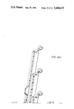
- FIG. 14 is a side elevational view of a lid according to the present invention and the embodiment of FIG. 3.
- lid flare has been a problem known and addressed for a long time.
- a tote box is designed for a particular customer who provides the input that their transport has a specific interior transport volume, which might be the height, length and width of the interior of a tractor trailer, and the customer will give a general statement of how big the box is to be.
- a customer always wants efficient return shipping the empty boxes so that the greatest number of empty boxes may be returned shipped without sacrificing other design criteria, which for plastic molded boxes with attached lids means that they are nested together when empty so that their attached lids will overly or shingle with respect to each other.
- the attached lid is a usual requirement to prevent loss of the lids and provide efficiency of handling. Therefore, the width, as measured horizontally perpendicular to the lid hinges, of nested boxes for the return trip is critical and lid flare has always been an undesirable increase in the width of nested boxes over full stacked boxes, which problem is a concern of the designer.
- the present inventor has analyzed the lid flare problem and determined that lid flare is to a great extent caused by interference between the ribs, (particularly when they are large ribs having the above-mentioned advantages) and other analogous structure, or interference between adjacent flanges or channels made up of the flanges that overlap the side walls of the boxes when the lids are closed.
- the most important flange is the outboard flange to vertically overlap the outside of the side wall, and an inboard flange may or may not be present.
- the flange is usually provided with a minimum flare, that is, a taper outwardly and downwardly when viewed from the closed position, for purposes of providing molding relief. Molding relief is the taper of an element to facilitate its removal from the mold. Such molding relief, even when exaggerated as shown in FIG. 10, is insufficient to provide for nesting of the side flanges or channels when the lids shingle, as will be explained more fully below.
- the inventor has analyzed this and determined that increasing of the flare for the inboard flange will provide nesting without any undesirable side effects, but that increasing the flare for the outboard flange would correspondingly increase the dimension of the tote boxes in the direction parallel to the hinges and reduced security, which would be considerable disadvantages.
- the present invention includes this analysis and the more particular solution of increasing the flare for only the inboard flange while tapering the outboard flange, in its depth, toward the hinge, which are respectively two of the three primary features of the present invention.
- FIG. 1 illustrates a preferred embodiment to the present invention
- the three primary features of the present invention are not readily viewable in FIG. 1.
- FIG. 1 is an illustration of a new box design, it employs the following conventional features.
- a molded one piece container structure includes a bottom 1, opposed end walls 2, 3, which slope upwardly and outwardly from opposed end edges of the bottom 1, and opposed side walls 4, 5, which slope upwardly and outwardly from opposed side edges of the bottom 1. No particular significance should be placed on the terms side an end, except to distinguish them.
- the side walls and end walls are joined at their common corners to form an open topped box.
- Lids 6, 7 are respectively hinged to the top portion of the end walls 2, 3.
- lids 6, 7 have raised portions 8 and depressed portions 9, (raised and depressed are terms relating the areas to each other and not other structure) which interengage as the lids 6, 7 are simultaneously moved into the closed position.
- the lid 6 is in its closed position, while the lid 7 is in a transition position rotated 180° from its closed position, for purposes of illustration. From the position of the lid 7, the hinge is such that the lid 7 would be gravity fall to a depending vertical position, which open position would be approximately 270° rotation from the closed position of lid 6.
- portions 8 are referred to as raised, they are preferably at the same level as the central portion of the lid and overly the depressed areas of the adjacent lid, when both lids are closed.
- the interengaging lids form a central planar landing surface to receive thereon the bottom of a like container, when full containers are stacked for transport or storage.
- some abutment means are provided around the periphery of the landing area, which may constitute lugs (conventional such as in the Frater patent though not shown), or a flange structure leading to the recessed landing area as shown, or the like.
- the landing area is preferably the same height as the tops of the side and end walls, although this is not necessary.
- the exact nature of the abutment means is not critical to the present invention, nor is the number of teeth or raised areas 8, nor are the details of the sides, bottom, lid or lids.
- each of the lids is provided with projecting structure, e.g. a plurality of ribs 10, of any suitable design or width.
- projecting structure e.g. a plurality of ribs 10, of any suitable design or width.
- the term bottom or top of the lid is with respect to its normal closed position that is illustrated in FIG. 1 with respect to lid 6, the width of a rib or other projecting structure is with reference to such closed position and a horizontal measurement, whereas the depth of a rib or other projecting structure would be its vertical measurement or projection from the bottom surface 24, when in such closed position of the lid.
- hinges used to hingedly secure the lid to the top edge of the end walls are not critically to the present invention, although it is necessary that the lids move through approximately 270° of rotation and preferably the hinges are such as to provide for a single axis of rotation for the lids, which is the most economical.
- some type of hook is usually provided between the overlying raised and depressed areas to prevent them from spreading apart horizontally.
- Such hooks may be in the form of hooks depending from the raised areas and apertures through the depressed areas as in the above-mentioned Bockenstette patent, or openings 11 in the side ribs of the raised areas that cooperate with upstanding lugs 12 of the depressed areas that will fit into such openings, or some other suitable structure.
- apertures 13, 14 may be respectively provided, in alignment, through the lid and upper horizontal flange 15 of the side walls so that a security tie (not shown and conventional) or rivet (not shown and conventional) may be passed through to provide for box security.
- each of the side walls have a recessed central portion including a vertical wall portion 16 that is offset inwardly and a horizontal wall portion 17, which structure increases the strength of the side walls and further provides a hand hold.
- each lid includes a horizontal flange 18 that overlies and engages the corresponding horizontal flange 15 of the side wall, to provide support for the central portion of the lids when in their closed position.
- the lid central portions may be recessed below the flange 15 or at the same level, as mentioned above, the present embodiment has the central portion recessed and connected to the horizontal flange 18 by an inboard vertical flange 19.
- An outboard vertical depending flange or skirt 20 is provided to overlap the outside of the side walls and to prevent someone from moving their hand between the lid and flange 15 when the lids are secured, as well as to prevent the lids from collapsing inwardly of the container when a load is placed in the center of the landing area when the lids are closed.
- FIG. 14 shows the lid 7 rotated 90° downward from its position in FIG. 1 and in a position that is 270°, approximately, of rotation from the position of lid 6 in FIG. 1.
- the hinge structure 21, having an axis of rotation 22, may be of any conventional type, for example as shown in the above-mentioned Bockenstette patent.
- the main portion of each lid is formed from a sheet of plastic having a generally uniform thickness, with a top surface 23 and bottom surface 24, with the top surface 23 forming the above-mentioned landing area and raised portions 8.
- the depressed area 9 has a top surface 26 and a bottom surface 27.
- the ribs 10 decrease in depth (as measured perpendicular to the landing area top surface 23) from the terminal end or interengaging end 27 of the lid to the hinge structure 21.
- These ribs may be continuous or discontinuous, step wise or continuously reducing in depth, or a mixture of the above, for example, that is the term taper is being used generally to mean that generally speaking the depth/height of projecting structure that would otherwise cause lid flare is reduced as it is closer to the hinge.
- the main point is that when the lids are shingled, in their open position with nested boxes, the top planar surface 23 of an upper box will lie adjacent the ribs 10 of a lower box, as seen, for example, in FIGS. 2 and 3. As seen in FIG.
- the terminal end 27 of an upper box is at a height above the terminal end of the next lower box lid, in the nested position. Therefore, the ribbing 10 may be of maximum desired depth below the terminal end 27 of the next highest box lid, because there is no possibility of the ribs engaging the next highest box lid below its terminal end 27, so that in such area, taper is not needed. Also, it is seen that the depressed area 9 extends out even further than the ribbing, but below the terminal end 27 of the next highest box.
- the extent to which the boxes nest is determined by outwardly extending vertical ribs or buttresses 28 on the side walls of the boxes, which constitute nesting stops having a bottom edge 29 that will engage the flange 15 or other structure of the next lowest box in a stack, in a conventional manner.
- the point is that the ribbing and other structure of the lids that extends from the bottom surface 24 of the lids below the interfering structure of the next highest shingled lid is not critical in determining lid flare.
- the remaining overlapping portion of the bottom surface of the lid, that is between the terminal end 30 of the rib 10 closest to the hinge structure (a reference point) and the reference point 31 on the same lid structure that is adjacent the terminal end 27 of the next highest lid in the nest constitutes the overlapping area for the bottom surface 24. It is this area that is generally tapered, in depth, from point 31 to point 30, at least. In the actual preferred embodiment, the taper is uniform. The taper should be such that from reference point 30 to reference point 31, all ribbing and the like projecting structure on the bottom of the lid should be towards the inside of a plane passing through such points, with point 30 being at a depth materially less than the depth of point 31, as measured from the plane of the top surface 23 forming the landing area.
- rib taper This is one major feature of the present invention and will generally be referred to as rib taper, with taper being broadly defined as mentioned above and ribs generally referring to any structure within the overlap area between points 30 and 31 that extends downwardly from the bottom surface 24, that might affect lid flare. The significance of this feature will become more apparent from a discussion below.
- the inboard flange 19A is preferably vertical or slightly flared for mold relief to provide a firm abutment to resist movement of the side walls inward and to resist lateral movement of a like box stacked upon the lid when in its closed position.
- the outboard flange 20a is preferably vertical or with a slight mold relief so that it will securely engage the side wall to resist inward bowing of the top when a heavy weight, foot or the like is placed in the center of the landing area, for example.
- any outward flare tends to increase the overall dimension of the box in the direction parallel to the hinge axis 22. Therefore, it is seen that even with the exaggerated flare shown in FIG. 10, with respect to the conventional structure, these flanges for adjacent lids in the shingled position will not nest, due to engagement between the edge of the outboard flange 20A and the flange 18A of the adjacent box lid, and/or the engagement between the lower edge of the flange 19A and the flange 18A of the adjacent box lid.
- the flange 18A is used loosely, to include, if present, the extension thereof in the form of a rib 10A.
- a second feature of the present invention is that the inboard flanges 19 (or the corresponding ribs in a nonrecessed top structure, for example as shown in the above-mentioned Frater patent) are downwardly and inwardly flared to a sufficient extent that they will nest within each other to an extent sufficient to provide the desired reduction in lid flare as compared to lid flare without such nesting of the inboard flanges.
- Such flaring is at an angle greater than conventional for mold relief, and sufficiently greater to provide the above-mentioned function. Since this flange is inboard, it in no way affects the exterior dimensions of the box.
- flange flare which includes an equivalent rib flare or skirt flare (not shown), particularly with respect to the preferred embodiment of a recessed lid.
- the flange flare may not be required, or at least to a lesser extent.
- the stacking lugs that is lugs that prevent lateral shifting of stacked boxes and function as the abutment means, should desirably be placed in the plurality of locations so that they will nest within stacking lugs of an adjacent box lid, for example the stacking lug closest to the end 27 of an upper lid may nest within the stacking lug that is second from the end 27 of the adjacent lower lid, in the nesting position.
- the flanges of the lugs would be flared to nest. That is, a structure that may be added and that is not shown in the present embodiments would have the concepts of the present invention applied thereto to reduce lid flare, if they would otherwise cause lid flare.
- the third major feature of the present invention relates to the outboard flange 20.
- the nesting of the inboard flange and/or moving of the shingled lids closer together according to the present invention to reduce lid flare is further permitted by a special structure for the outboard flange 20. Again, this is only critical in the overlap area between points 30 and 31, and the outboard flange may have a maximum and even uniform downward extent in the areas below point 31, for example in FIG. 3.
- this outboard flange 20 is tapered, in general, from at least the point 31 to the point 30 or toward the hinge structure 21.
- the tapering, as with the ribs may be stepwise, continuous or discontinuous. In the preferred embodiment, as shown in FIG.
- the lowermost edge 32 of the outboard flange 20 is tapered toward the top surface 23 from at least the point 31 to the point 30.
- the outboard flange 20 may be maintained as close to vertical as desired, for the above-mentioned advantages, while still reducing lid flare.
- the material used for construction may be prime high density polyethylene, which is injection molded with a wall thickness of 0.14 inches.
- FIG. 12 The only difference between the boxes shown in FIGS. 12 and 13 is that the structure of FIG. 13 has been modified according to the present invention to reduce lid flare, which reduction amounts to 22%.
- the only difference between the structures shown in FIGS. 2 and 3 is that in FIG. 3 the features of the present invention have been employed to reduce lid flare. Since prototypes for the box of FIGS. 3 have been constructed, it has been determined that if the features of the present invention were not employed, the lid flare would be increased 35% as shown in FIG. 2.
- lid flare is defined, at least in this application, as follows. In the nested position of the empty containers, the lids will be shingled as shown in the various figures. With the boxes resting upon a horizontal flat surface, the hinge axes 22 for a vertically adjacent lids will all lie in a vertical plane, referred to as the axis plane for the lids. If one takes the furthest point outward from the axis plane for the box structure without the lid, which with the illustrated embodiments would be the outermost point of the buttress or nesting stop 28, a plane BB passing through such point would determine one limit for the lid flare and may be referred to as the lid flare inboard plane.
- the lowermost lid in a shingled stack lies the closest to vertical, while the other lids, due to contact, are rotated outward therefrom.
- the lids will assume a fixed position, relatively speaking. This number is as follows for the various boxes shown in the figures: FIG. 2, 4; FIG. 3, 4; FIG. 9, 5 or 6; FIG. 11, 6; FIG. 12, 4; FIG. 13, 4.
- the lid that is rotated outward the most due to such contact would have the outermost point for the shingled lids, and the vertical plane AA passing through such point would be referred to as the outermost lid flare plane.
- the distance between the innermost lid flare plane BB and the outermost lid flare plane AA would be referred to as the amount of lid flare, which should be the same for each end of the box if two attached lids are used.
- the lid flare is 1.62 inches, whereas without the features of the present invention it is determined to be 2.19 inches as shown in FIG. 2.
- the lid flare is 3.38 inches, whereas if such box structure is modified according to the teachings of the present invention, the lid flare is calculated to be 2.19 inches, with a reduction of 35% in lid flare.
- the lid flare is 2.38 inches, whereas with the same box structure modified according to the teachings of the present invention as shown in FIG. 13, the lid flare is determined to be 1.86 inches, with a 22% reduction in lid flare.
- the lid flare is increased 35%.
- the lid flare of course is also determined in amount by the size of the boxes.
- the above-mentioned boxes that have been illustrated in the Figures represent a wide and commercial range of box sizes and nesting ratios, as well as different box structures.
- the customer has a desired transport volume, for example the interior of a truck.
- the width of the truck interior is the starting dimension to be considered for lid flare. Let this width be dimension x.
- the customer may have a general idea of box size and weight when loaded that would be convenient for handling or the like, which according to the transport size would mean that 9 boxes could be placed side by side across the width of the truck, so that each box can have only a miximum width of x/9.
- the boxes have their maximum width when they are empty, nested and have their lids open and shingled as shown in the various figures. With two lids for each box, it is seen that allowance must be made for lid flare on each side of the box, so that the maximum box width, without lids, would be x/9 minus 2 times the lid flare.
- the amount of room taken up by the side walls and side wall tapered to permit nesting has been refined considerbly over the years and is fairly fixed, so that now the interior of the box has been determined insofar as its width is concerned, and the interior width controls to a great extent the volume of the box and therefore how much the box may carry, which is critical to the customer.
- any reduction in lid flare amount is multiplied by 2 and may be applied to increase the interior width of the box and thereby increase the volume and holding capacity of the box.
- These are known design criteria and with respect to this specific type of box have been well known since the introduction of the Bockenstette box in 1968, and known for single lided for much longer, e.g. 1938.
- These boxes are widely used and sold in large volumes by many different companies, but the analysis set forth in regard to the description of the present invention and the features flowing therefrom, primarily three in number, leading towards the present invention have produced lid flare reductions of between 22% and 35% with actual commercial boxes.
- the box according to FIGS. 2 and 3 have an overall height of 9 inches, interior height of 7.86 inches, general interior width of 7.64 inches, as measured parallel to the hinges and 6.63 inches as measured perpendicular to the hinges at the bottom.
- the maximum horizontal dimension of the box with the lids closed is 8.56 inches perpendicular to the hinges and 9.75 inches parallel to the hinges.
- the dimension perpendicular to the hinges increases to a maximum size of 10.12 inches with both lids open with respect to the bottom box.
- the features in the present invention can reduce lid flare from 2.19 inches to 1.62 inches or 0.57 inches for each side, which would be 1.14 inches per box therefore available according to the present invention to be applied to the interior volume.
- the interior dimension for the bottom of the box employing the features of the present invention is 6.63 inches, and it therefore can be seen that if the features of the present invention were not employed this dimension would be reduced by the above-mentioned 1.14 inches, or would become 5.49 inches, which is a considerable loss in usable space. Or alternatively viewed, the present invention provides a considerable gain in usable interior space for each box. When it is considered that one customer employs thousand of such boxes usually for the daily distribution of goods, such a saving of space becomes very considerable with respect to corresponding savings in handling, fuel, transports, shipping time, storage space, available inventory, and the like.
- the variation in depth of the flange 20 and depth of the ribbing 10 can be particularly seen in the various cross-sectional views 4, 5, 6, 7 and 8.
- the angle of the flare for the flange 19 preferably remains the same for its entire length, but it is possible that it could change. It is seen, for example from a comparison of FIGS. 4 and 8, that reduction in rib depth and the depth of flange 20 (including its elimination) is necessary to permit the top surfaces 23 of adjacent lids to move closer towards each other, at any particular point. It can be seen from FIG.
Abstract
Description
Claims (13)
Priority Applications (3)
| Application Number | Priority Date | Filing Date | Title |
|---|---|---|---|
| US06/706,318 US4688675A (en) | 1985-02-27 | 1985-02-27 | Nesting box with reduced lid flares |
| CA000494126A CA1248468A (en) | 1985-02-27 | 1985-10-29 | Nesting box with reduced lid flares |
| US07/398,774 USRE33384E (en) | 1985-02-27 | 1989-08-25 | Nesting box with reduced lid flares |
Applications Claiming Priority (1)
| Application Number | Priority Date | Filing Date | Title |
|---|---|---|---|
| US06/706,318 US4688675A (en) | 1985-02-27 | 1985-02-27 | Nesting box with reduced lid flares |
Related Child Applications (1)
| Application Number | Title | Priority Date | Filing Date |
|---|---|---|---|
| US07/398,774 Reissue USRE33384E (en) | 1985-02-27 | 1989-08-25 | Nesting box with reduced lid flares |
Publications (1)
| Publication Number | Publication Date |
|---|---|
| US4688675A true US4688675A (en) | 1987-08-25 |
Family
ID=24837065
Family Applications (1)
| Application Number | Title | Priority Date | Filing Date |
|---|---|---|---|
| US06/706,318 Ceased US4688675A (en) | 1985-02-27 | 1985-02-27 | Nesting box with reduced lid flares |
Country Status (2)
| Country | Link |
|---|---|
| US (1) | US4688675A (en) |
| CA (1) | CA1248468A (en) |
Cited By (22)
| Publication number | Priority date | Publication date | Assignee | Title |
|---|---|---|---|---|
| US4930681A (en) * | 1988-08-18 | 1990-06-05 | Clinton Fultz | Automatic latching container having good thermal insulation |
| US5328048A (en) * | 1993-02-08 | 1994-07-12 | Otto Industries, Inc. | Tote box |
| US5353948A (en) * | 1993-04-28 | 1994-10-11 | Ipl Inc. | Plastic container with hinged lids |
| EP0620159A1 (en) * | 1993-04-12 | 1994-10-19 | Buckhorn Material Handling Group, Inc. | Bi-fold lid for container |
| GB2289884A (en) * | 1994-06-03 | 1995-12-06 | Schaefer Gmbh Fritz | Stackable container |
| WO1996023703A1 (en) * | 1995-02-02 | 1996-08-08 | Rehrig Pacific Company, Inc. | Container assembly with tamper evident seal |
| US5555996A (en) * | 1993-08-06 | 1996-09-17 | Rehrig Pacific Company | Bag-in box with split lid |
| US5673791A (en) * | 1994-10-04 | 1997-10-07 | Buckhorn Material Handling Group, Inc. | Container and lid for container |
| US5947451A (en) * | 1997-08-20 | 1999-09-07 | Cavanagh; Paul D. | Marine winch drum |
| US6318586B1 (en) * | 1998-12-18 | 2001-11-20 | Menasha Corporation | Plastic tote box improvements |
| US20090173744A1 (en) * | 2008-01-03 | 2009-07-09 | Hassell Jon P | Container with lid |
| US20100282752A1 (en) * | 2009-05-11 | 2010-11-11 | Multisteps Pty. Ltd. | Produce container |
| US8616370B2 (en) | 2010-10-28 | 2013-12-31 | Arrows Up, Inc. | Bulk material shipping container |
| US8887914B2 (en) | 2010-10-28 | 2014-11-18 | Arrows Up, Inc. | Bulk material shipping container |
| GB2522091A (en) * | 2014-01-10 | 2015-07-15 | Loadhog Ltd | Container |
| US9205951B1 (en) | 2014-07-24 | 2015-12-08 | Josephine E. Roman | All-in-one stackable bulletin board caddy |
| US9522763B2 (en) | 2014-07-24 | 2016-12-20 | Josephine E. Roman | All-in-one stackable bulletin board caddy |
| US20170370135A1 (en) * | 2016-06-22 | 2017-12-28 | Nova Chemicals (International) S.A. | Hinged component made from high density unimodal polyethylene |
| WO2019002804A1 (en) * | 2017-06-29 | 2019-01-03 | Loadhog Limited | Improvements in or relating to lid arrangements |
| US10676239B2 (en) | 2016-06-30 | 2020-06-09 | Sandbox Logistics, Llc | Bulk material shipping container |
| US10926940B2 (en) | 2018-11-20 | 2021-02-23 | Sandbox Enterprises, Llc | Bulk material shipping container |
| US11661235B2 (en) | 2018-10-15 | 2023-05-30 | Sandbox Enterprises, Llc | Bulk material shipping container top wall assembly and bulk material shipping container having a top wall assembly |
Citations (11)
| Publication number | Priority date | Publication date | Assignee | Title |
|---|---|---|---|---|
| US2112451A (en) * | 1937-08-23 | 1938-03-29 | Wilson F Best | Stacking and nesting box or receptacle |
| US2803369A (en) * | 1955-06-14 | 1957-08-20 | Properties Inc | Pallet carrier |
| US3351229A (en) * | 1965-11-18 | 1967-11-07 | Phillips Petroleum Co | Nesting and stacking container |
| US3383009A (en) * | 1967-03-17 | 1968-05-14 | Gen Films Inc | Container |
| US3463345A (en) * | 1968-08-28 | 1969-08-26 | Ms Ind Inc | Lidded tote box |
| GB1223247A (en) * | 1968-12-06 | 1971-02-24 | Fuji Photo Film Co Ltd | Camera with a rectractable lens barrel |
| US4161261A (en) * | 1978-05-05 | 1979-07-17 | Menasha Corporation | Security container |
| US4325492A (en) * | 1980-05-22 | 1982-04-20 | Cities Service Company | Covered container |
| US4349108A (en) * | 1979-04-19 | 1982-09-14 | W. H. D. Development Limited | Containers |
| US4432467A (en) * | 1982-03-08 | 1984-02-21 | Menasha Corporation | Reinforced lid construction for security containers or the like |
| GB2147567A (en) * | 1983-10-11 | 1985-05-15 | Wcb Mailbox Limited | Nestable storage bin |
-
1985
- 1985-02-27 US US06/706,318 patent/US4688675A/en not_active Ceased
- 1985-10-29 CA CA000494126A patent/CA1248468A/en not_active Expired
Patent Citations (11)
| Publication number | Priority date | Publication date | Assignee | Title |
|---|---|---|---|---|
| US2112451A (en) * | 1937-08-23 | 1938-03-29 | Wilson F Best | Stacking and nesting box or receptacle |
| US2803369A (en) * | 1955-06-14 | 1957-08-20 | Properties Inc | Pallet carrier |
| US3351229A (en) * | 1965-11-18 | 1967-11-07 | Phillips Petroleum Co | Nesting and stacking container |
| US3383009A (en) * | 1967-03-17 | 1968-05-14 | Gen Films Inc | Container |
| US3463345A (en) * | 1968-08-28 | 1969-08-26 | Ms Ind Inc | Lidded tote box |
| GB1223247A (en) * | 1968-12-06 | 1971-02-24 | Fuji Photo Film Co Ltd | Camera with a rectractable lens barrel |
| US4161261A (en) * | 1978-05-05 | 1979-07-17 | Menasha Corporation | Security container |
| US4349108A (en) * | 1979-04-19 | 1982-09-14 | W. H. D. Development Limited | Containers |
| US4325492A (en) * | 1980-05-22 | 1982-04-20 | Cities Service Company | Covered container |
| US4432467A (en) * | 1982-03-08 | 1984-02-21 | Menasha Corporation | Reinforced lid construction for security containers or the like |
| GB2147567A (en) * | 1983-10-11 | 1985-05-15 | Wcb Mailbox Limited | Nestable storage bin |
Cited By (40)
| Publication number | Priority date | Publication date | Assignee | Title |
|---|---|---|---|---|
| US4930681A (en) * | 1988-08-18 | 1990-06-05 | Clinton Fultz | Automatic latching container having good thermal insulation |
| US5328048A (en) * | 1993-02-08 | 1994-07-12 | Otto Industries, Inc. | Tote box |
| EP0620159A1 (en) * | 1993-04-12 | 1994-10-19 | Buckhorn Material Handling Group, Inc. | Bi-fold lid for container |
| US5353948A (en) * | 1993-04-28 | 1994-10-11 | Ipl Inc. | Plastic container with hinged lids |
| US5555996A (en) * | 1993-08-06 | 1996-09-17 | Rehrig Pacific Company | Bag-in box with split lid |
| GB2289884A (en) * | 1994-06-03 | 1995-12-06 | Schaefer Gmbh Fritz | Stackable container |
| US5673791A (en) * | 1994-10-04 | 1997-10-07 | Buckhorn Material Handling Group, Inc. | Container and lid for container |
| WO1996023703A1 (en) * | 1995-02-02 | 1996-08-08 | Rehrig Pacific Company, Inc. | Container assembly with tamper evident seal |
| US5967322A (en) * | 1995-02-02 | 1999-10-19 | Rehrig Pacific Company, Inc. | Container assembly with tamper evident seal |
| US5947451A (en) * | 1997-08-20 | 1999-09-07 | Cavanagh; Paul D. | Marine winch drum |
| US6318586B1 (en) * | 1998-12-18 | 2001-11-20 | Menasha Corporation | Plastic tote box improvements |
| US6431394B2 (en) | 1998-12-18 | 2002-08-13 | Menasha Corporation | Plastic tote box improvements |
| US20090173744A1 (en) * | 2008-01-03 | 2009-07-09 | Hassell Jon P | Container with lid |
| US20100282752A1 (en) * | 2009-05-11 | 2010-11-11 | Multisteps Pty. Ltd. | Produce container |
| US9617065B2 (en) | 2010-10-28 | 2017-04-11 | Arrows Up, Llc | Bulk material shipping container |
| US9988182B2 (en) | 2010-10-28 | 2018-06-05 | Arrows Up, Llc | Bulk material shipping container |
| US11059622B2 (en) | 2010-10-28 | 2021-07-13 | Sandbox Enterprises, Llc | Bulk material shipping container |
| US10486854B2 (en) | 2010-10-28 | 2019-11-26 | Arrows Up, Llc | Bulk material shipping container |
| US10189599B2 (en) | 2010-10-28 | 2019-01-29 | Arrows Up, Llc | Bulk material shipping container |
| US8887914B2 (en) | 2010-10-28 | 2014-11-18 | Arrows Up, Inc. | Bulk material shipping container |
| US8616370B2 (en) | 2010-10-28 | 2013-12-31 | Arrows Up, Inc. | Bulk material shipping container |
| US9758993B1 (en) | 2010-10-28 | 2017-09-12 | Arrows Up, Llc | Bulk material shipping container |
| US9783338B1 (en) | 2010-10-28 | 2017-10-10 | Arrows Up, Llc | Bulk material shipping container |
| US9796504B1 (en) | 2010-10-28 | 2017-10-24 | Arrows Up, Llc | Bulk material shipping container |
| US9828135B2 (en) | 2010-10-28 | 2017-11-28 | Arrows Up, Llc | Bulk material shipping container |
| GB2522091B (en) * | 2014-01-10 | 2018-10-17 | Loadhog Ltd | Container |
| US10227159B2 (en) | 2014-01-10 | 2019-03-12 | Loadhog Limited | Nestable containers having nestable lid arrangements |
| GB2522091A (en) * | 2014-01-10 | 2015-07-15 | Loadhog Ltd | Container |
| WO2015104521A1 (en) * | 2014-01-10 | 2015-07-16 | Loadhog Limited | Container |
| US9205951B1 (en) | 2014-07-24 | 2015-12-08 | Josephine E. Roman | All-in-one stackable bulletin board caddy |
| US9522763B2 (en) | 2014-07-24 | 2016-12-20 | Josephine E. Roman | All-in-one stackable bulletin board caddy |
| US20170370135A1 (en) * | 2016-06-22 | 2017-12-28 | Nova Chemicals (International) S.A. | Hinged component made from high density unimodal polyethylene |
| US10584523B2 (en) * | 2016-06-22 | 2020-03-10 | Nova Chemicals (International) S.A. | Hinged component made from high density unimodal polyethylene |
| US10676239B2 (en) | 2016-06-30 | 2020-06-09 | Sandbox Logistics, Llc | Bulk material shipping container |
| GB2567033A (en) * | 2017-06-29 | 2019-04-03 | Loadhog Ltd | Improvements In Or Relating To Lid Arrangements |
| WO2019002804A1 (en) * | 2017-06-29 | 2019-01-03 | Loadhog Limited | Improvements in or relating to lid arrangements |
| GB2567033B (en) * | 2017-06-29 | 2021-12-01 | Loadhog Ltd | Interlocking lids with reinforcing ribs for stackable nestable containers |
| US11338965B2 (en) | 2017-06-29 | 2022-05-24 | Loadhog Limited | Or relating to lid arrangements |
| US11661235B2 (en) | 2018-10-15 | 2023-05-30 | Sandbox Enterprises, Llc | Bulk material shipping container top wall assembly and bulk material shipping container having a top wall assembly |
| US10926940B2 (en) | 2018-11-20 | 2021-02-23 | Sandbox Enterprises, Llc | Bulk material shipping container |
Also Published As
| Publication number | Publication date |
|---|---|
| CA1248468A (en) | 1989-01-10 |
Similar Documents
| Publication | Publication Date | Title |
|---|---|---|
| US4688675A (en) | Nesting box with reduced lid flares | |
| US4470518A (en) | Security box having a sliding lid | |
| US4620644A (en) | Tote box with lid container | |
| US5328048A (en) | Tote box | |
| US4062467A (en) | Collapsible transport container | |
| US5042674A (en) | Moving and storage container | |
| US5076457A (en) | Folding crate for holding packages | |
| US5555996A (en) | Bag-in box with split lid | |
| US6338181B1 (en) | Reusable produce crate | |
| US4192430A (en) | Laterally openable storage and transport box | |
| CA2254321C (en) | High strength container with interior button latch | |
| US7617947B2 (en) | Stackable storage/transport/stocking box with openable end | |
| US5758791A (en) | Latching mechanism for a plastic container | |
| US4523692A (en) | Reversible security cover for stackable and nestable tote box | |
| CA1109405A (en) | Security container | |
| AU675486B2 (en) | Improved stackable container | |
| US6286701B1 (en) | Container, in particular for transporting fruits and vegetables | |
| US6367630B1 (en) | High stacking-strength container | |
| US4901859A (en) | Container | |
| US3672530A (en) | Tray collar and tray-collar combinations | |
| USRE33384E (en) | Nesting box with reduced lid flares | |
| EP1189814A1 (en) | Collapsible container provided with a stacking ledge | |
| CA2057220C (en) | Nestable and stackable containers | |
| US4023680A (en) | Bakery tray | |
| US6276530B1 (en) | Container |
Legal Events
| Date | Code | Title | Description |
|---|---|---|---|
| AS | Assignment |
Owner name: BUCKHORN MATERIAL HANDLING GROUP, INC. 502 TECHNEC Free format text: ASSIGNMENT OF ASSIGNORS INTEREST.;ASSIGNORS:MILLER, DANIEL R.;DEATON, THOMAS P.;REEL/FRAME:004422/0162 Effective date: 19850219 |
|
| AS | Assignment |
Owner name: CHRYSLER CAPITAL CORPORATION, GREENWICH OFFICE PAR Free format text: SECURITY INTEREST;ASSIGNOR:BUCKHORN MATERIAL HANDLING GROUP INC.;REEL/FRAME:004634/0769 Effective date: 19860901 Owner name: BANCOHIO NATIONAL BANK, 155 EAST BROAD STREET, COL Free format text: SECURITY INTEREST;ASSIGNOR:BUCKHORN MATERIAL HANDLING GROUP INC.;REEL/FRAME:004634/0769 Effective date: 19860901 Owner name: CHRYSLER CAPITAL CORPORATION, CONNECTICUT Free format text: SECURITY INTEREST;ASSIGNOR:BUCKHORN MATERIAL HANDLING GROUP INC.;REEL/FRAME:004634/0769 Effective date: 19860901 Owner name: BANCOHIO NATIONAL BANK, OHIO Free format text: SECURITY INTEREST;ASSIGNOR:BUCKHORN MATERIAL HANDLING GROUP INC.;REEL/FRAME:004634/0769 Effective date: 19860901 |
|
| STCF | Information on status: patent grant |
Free format text: PATENTED CASE |
|
| AS | Assignment |
Owner name: BUCKHORN MATERIAL HANDLING GROUP, INC., AN OHIO CO Free format text: RELEASED BY SECURED PARTY;ASSIGNOR:CHRYSLER CAPITAL CORPORATION;REEL/FRAME:005080/0726 Effective date: 19890414 |
|
| RF | Reissue application filed |
Effective date: 19890825 |
|
| AS | Assignment |
Owner name: BUCKHORN MATERIAL HANDLING GROUP, INC., A CORP. OF Free format text: RELEASED BY SECURED PARTY;ASSIGNOR:BANCOHIO NATIONAL BANK;REEL/FRAME:005285/0507 Effective date: 19900130 |
|
| FEPP | Fee payment procedure |
Free format text: PAYOR NUMBER ASSIGNED (ORIGINAL EVENT CODE: ASPN); ENTITY STATUS OF PATENT OWNER: LARGE ENTITY |
|
| FPAY | Fee payment |
Year of fee payment: 4 |