US4696230A - Adjustable bustle-forming apparatus for maintaining registration of multicolor images on printing webs - Google Patents
Adjustable bustle-forming apparatus for maintaining registration of multicolor images on printing webs Download PDFInfo
- Publication number
- US4696230A US4696230A US06/911,397 US91139786A US4696230A US 4696230 A US4696230 A US 4696230A US 91139786 A US91139786 A US 91139786A US 4696230 A US4696230 A US 4696230A
- Authority
- US
- United States
- Prior art keywords
- stem
- bustle
- air
- wheel
- web
- Prior art date
- Legal status (The legal status is an assumption and is not a legal conclusion. Google has not performed a legal analysis and makes no representation as to the accuracy of the status listed.)
- Expired - Lifetime
Links
Images


Classifications
-
- B—PERFORMING OPERATIONS; TRANSPORTING
- B41—PRINTING; LINING MACHINES; TYPEWRITERS; STAMPS
- B41F—PRINTING MACHINES OR PRESSES
- B41F13/00—Common details of rotary presses or machines
- B41F13/02—Conveying or guiding webs through presses or machines
- B41F13/025—Registering devices
-
- B—PERFORMING OPERATIONS; TRANSPORTING
- B65—CONVEYING; PACKING; STORING; HANDLING THIN OR FILAMENTARY MATERIAL
- B65H—HANDLING THIN OR FILAMENTARY MATERIAL, e.g. SHEETS, WEBS, CABLES
- B65H23/00—Registering, tensioning, smoothing or guiding webs
- B65H23/02—Registering, tensioning, smoothing or guiding webs transversely
- B65H23/032—Controlling transverse register of web
-
- Y—GENERAL TAGGING OF NEW TECHNOLOGICAL DEVELOPMENTS; GENERAL TAGGING OF CROSS-SECTIONAL TECHNOLOGIES SPANNING OVER SEVERAL SECTIONS OF THE IPC; TECHNICAL SUBJECTS COVERED BY FORMER USPC CROSS-REFERENCE ART COLLECTIONS [XRACs] AND DIGESTS
- Y10—TECHNICAL SUBJECTS COVERED BY FORMER USPC
- Y10S—TECHNICAL SUBJECTS COVERED BY FORMER USPC CROSS-REFERENCE ART COLLECTIONS [XRACs] AND DIGESTS
- Y10S101/00—Printing
- Y10S101/42—Means for tensioning webs
Definitions
- This invention relates to multcolor printing presses having successive printing units for printing images or impressions of different colors on a printing web, usually made of paper.
- a printing press of this type has four printing units for use in four-color printing.
- Multicolor printing presses often employ the offset printing process, in which inked images are transferred from a printing plate to a rubber covered offset cylinder, and then to the paper printing web.
- the paper web passes through the first printing unit and is printed with a first color image.
- the passage of the paper web through the first printing unit causes the web to fan out, or be increased a small amount in width, so that the width of the first printed image is also increased.
- the first printed image is no longer in perfect register with the second printed image, produced by the second printing unit.
- This fanning out or increased width of the printing web tends to occur as the web passes through each of the printing units, and then travels to the next printing unit.
- This problem of web fanout, or increased web width due to the printing action of the printing press units, makes it impossible to achieve perfect crosswise or lateral registration between the successively printed color images in a multicolor printing press.
- the bustling wheel has generally been made of steel or nylon and has been mounted on a threaded rod, so that the wheel can be screw adjusted, up or down, to apply pressure on the printed web.
- the use of the bustle wheel has the disadvantage that it can smear the ink or produce tracking marks on the printed web, unless the wheel can be brought into engagement with a clear unprinted longitudinal area on the printed web.
- One object of the present invention is to provide a new and improved combination wheel-air bustling device, having both a bustling wheel and a bustling air nozzle which may be selectively employed to produce a bustle in a printing web, between successive printing units of a printing press, for effectively shrinking the width of the web to its original width, and thereby establishing and maintaining precise registration between the successive images printed by the printing units on the web.
- a further object is to provide such a new and improved combination wheel-air bustling device, having means for selecting between the use of the bustling wheel and the air nozzle; means for adjusting the lateral position of the device across the width of the printing web, to adjust the location of the bustle; means for precisely adjusting the position of the bustling air nozzle or wheel, whichever is selected, in a direction perpendicular to the printing web, to adjust the depth of the bustle; and means for precisely adjusting the supply of compressed air to the air nozzle, for additionally controlling the depth of the bustle.
- a further object is to provide a new and improved bustling apparatus, incorporating a plurality of such wheel-air bustling devices into a complete system, in which one or more such bustling devices are adjustably positioned between each pair of successive printing units, with provision for individually adjusting the positions of the bustling devices, and provision for controlling the supply of compressed air to each of the air nozzles, as well as provision for controlling the supply of compressed air to all of the air nozzles collectively.
- one or more bustles of precisely adjustable location and depth may be formed in the printing web between each successive pair of printing units, by using either bustle wheels or bustle air nozzles, or any combination thereof, for effectively shrinking the width of the web to its original width, whereby all of the successively printed color images can be precisely registered with one another.
- a combination wheel-air bustling device for producing an adjustable bustle in a printing web as it travels between successive printing units of a multicolor printing press, such device comprising supporting means having mounting means for mounting such supporting means in a selected location between the successive printing units and opposite the printing web, carriage means movably mounted on such supporting means for movement in a direction generally perpendicular to the printing web, air nozzle means mounted on such carriage means to direct an air jet against the web for producing a bustle therein, bustle wheel means mounted on such carriage means to engage and deflect the web for producing a bustle therein, selecting means to produce relative movement between the bustle wheel means and the air nozzle means for selectively bringing either the air nozzle means or the bustle wheel means into its operative bustle-forming relationship with the printing web to form a bustle therein, and adjusting means for producing adjusting movement of the carriage means and the selected air nozzle means or bustle wheel means in a direction generally perpendicular to the
- the supporting means may include a supporting body having a guide opening therein.
- the carriage means may include a hollow tubular stem movably received in such guide opening for movement in a direction generally perpendicular to the printing web.
- Such stem preferably has a longitudinal air supply opening extending therein.
- the air nozzle means may include an air nozzle connected to one end of such air supply opening for movement with such stem, toward and away from the web.
- the stem may have means connected to the other end of the air supply opening for supplying compressed air thereto.
- Such adjusting means may comprise an adjusting mechanism connected between the body and the stem for producing adjusting movement of the stem through the guide opening.
- the adjusting mechanism preferably comprises a rotatable adjusting knob rotatably retained on the supporting body and having a bore aligned with such guide opening and formed with internal screw threads.
- the stem preferably extends through such bore and has external screw threads mating with such internal screw threads, whereby rotation of such knob causes adjusting movement of the stem through the guide opening.
- the supporting body preferably includes a pair of fork portions with a slot therebetween for rotatably receiving and retaining the adjusting knob.
- a retaining device may be provided to retain the adjustment of the stem relative to the body.
- the bustle wheel means may comprise a bustle wheel frame mounted on the stem, and a bustle wheel rotatably mounted on such frame.
- the selecting means may comprise a portion of such bustle wheel frame, formed with a stem opening in which such stem is movably received to provide for adjusting movement of such frame along the stem relative to the air nozzle, whereby the bustle wheel is movable into and out of operative engagement with the printing web.
- the wheel frame may have a clamping screw or some other retaining means for retaining the adjustment of the frame along the stem.
- the mounting means may comprise a transverse supporting bore, extending generally parallel with the web and transversely to the direction of the stem.
- the supporting body may have a transverse opening for movably receiving such transverse supporting bar.
- a clamping screw or other clamping means may be provided for selectively clamping the body to the transverse supporting bar.
- the air nozzle is adapted to be connected to a compressed air supply system, preferably including a fully adjustable air regulating valve for adjusting the pressure of the compressed air supplied to the air nozzle, and thereby adjusting the strength of the air jet and the depth of the air bustle in the printing web.
- An ON-OFF air valve is preferably connected in series with the regulating valve for turning on and shutting off the supply of compressed air to the nozzle.
- the present invention also preferably provides an apparatus comprising a plurality of such wheel-air bustling devices, mounted in a laterally spaced arrangement, adapted to be positioned between the printing units and opposite transversely spaced portions of the printing web to form a plurality of transversely spaced bustles therein.
- the bustling devices may be arranged in a plurality of groups, adapted to be mounted between successive printing units of a multicolor printing press.
- the bustling devices are preferably provided with individual fully adjustable air regulating valves for individually adjusting the pressure of the compressed air supplied to the individual air nozzles. Thus, the depth of each air bustle can be adjusted individually.
- the air nozzles are also preferably provided with individual ON-OFF air valves.
- the compressed air supply system may also be provided with master ON-OFF air valves for shutting off the various groups of the air nozzles, and for shutting off all of the air nozzles.
- the ON-OFF air valves are preferably solenoid operated, to provide for convenient electrical remote control, by a bank of electrical switches, mounted on a control panel.
- the bustle frames and wheels can be removed from the adjustable stems of the bustling devices.
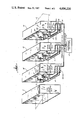
- FIG. 1 is a somewhat diagrammatic perspective view, illustrating a multicolor printing press equipped with a bustling apparatus incorporating a multiplicity of wheel-air bustling devices to be described as illustrative embodiments of the present invention, such bustling devices being mounted between the successive printing units of the printing press for bustling the printed web.
- FIG. 2 is an end elevational view, illustrating one of the wheel-air bustling devices, with the bustling wheel adjusted to the wheel-bustling position, in which the wheel protrudes beyond the air nozzle for bustling the printed web.
- FIG. 3 is a side elevation of the bustling device, as shown in FIG. 2.
- FIG. 4 is an end view showing the opposite end of the bustling device of FIGS. 2 and 3.
- FIG. 5 is a perspective view illustrating the bustling device, as shown in FIGS. 2-4.
- FIG. 6 is a perspective view, similar to FIG. 5, but showing the bustling device with the bustling wheel withdrawn relative to the air nozzle, so that the bustling wheel is inactivated, while the air nozzle is in a position to form a bustle in the printing web.
- FIG. 7 is an end elevation showing the bustling device adjusted for air bustling, as in FIG. 6.
- FIG. 8 is a side elevation of the bustling device with the bustle wheel retracted and with the air nozzle brought into a closely spaced relation with the printed web to form a bustle therein.
- FIG. 9 is an opposite end elevation showing the bustling device as illustrated in FIGS. 6-8.
- FIG. 10 is an exploded or disassembled perspective view of the bustling device of FIGS. 1-9, having an air nozzle and a bustling wheel for selectively producing a bustle in the printed web.
- FIG. 11 is a longitudinal section, taken through the air nozzle of FIG. 10.
- FIG. 12 is a cross sectional view, taken through the printed web and illustrating the formation of bustles in the web by three of the bustling devices, as shown in FIG. 7.
- FIG. 12a is a cross sectional view showing the web without bustling, for comparison with FIG. 12, to illustrate the manner in which the bustling action shrinks the width of the web.
- FIG. 1 shows a bustling apparatus, constituting an illustrative embodiment of the present invention, as applied to a multicolor printing press, which includes first, second, third and fourth printing units 1, 2, 3 and 4, adapted to print four superimposed images or impressions of different colors on a paper printing web 5, as it is fed through the successive printing units.
- the printing action of the first printing unit 1 tends to cause the printed web 5 to fan out to a slightly increased width, as the web passes through and emerges from the first printing unit.
- This fanout presents a problem, in that the first printed image also is increased slightly in width, so that the first image does not register perfectly with the second printed image, produced by the second printing unit.
- Such fanning out of the web 5 also tends to occur as the web passes through and emerges from the second and third printing units 2 and 3.
- each of the first three printed images tends to be widened slightly, so that it does not register perfectly with the next printed image.
- the present invention causes the web to shrink back to its original width, by providing bustling means between the successive printing units, to form longitudinal bustles or ridges in the printed web, whereby the web is restored to its original width.
- the complete bustling means or apparatus takes the form of three bustling systems or groups 6, 7 and 8, disposed in the three spaces between the four printing units 1-4.
- Each of the bustling systems 6, 7 and 8 comprises one or more bustling devices, adapted to form transversely spaced bustles in the printed web 5.
- each of the bustling systems 6, 7 and 8 comprises three such bustling units 9, 10 and 11, all of which may be substantially the same in construction.
- Each of the bustling devices 9-11 is adapted to provide either wheel bustling or air bustling, as selected by the operator.
- the apparatus of FIG. 1 includes a COMPRESSED AIR SOURCE 12, to supply pressurized air to all of the bustling devices 9-11.
- a master ON-OFF valve 13, preferably solenoid operated, is connected into the air line 14, extending from the compressed air source 12, for turning on and shutting off the supply of compressed air to all of the bustling devices 9-11 in all of the bustling systems 6-8.
- the air line system has three branches including ON-OFF valves 15, 16 and 17, which are preferably solenoid operated.
- the valve 15 controls the supply of compressed air to the bustling system 8; the valve 16 to the bustling system 7; and the valve 17, to the bustling system 6.
- Each of the three bustling systems 6, 7 and 8 includes three ON-OFF valves 18, 19 and 20, preferably solenoid operated, for controlling the supply of compressed air to the individual bustling devices.
- the bustling devices identified as 21, 22 and 23, are supplied with compressed air by the ON-OFF valves 18, 19 and 20, respectively.
- fully adjustable air flow regulating valves 24, 25 and 26 are connected in series with the ON-OFF valves 18, 19 and 20, to regulate the pressure of the compressed air supplied to the bustling devices 21, 22 and 23, respectively.
- FIGS. 2-9 show details of an assembled bustling device, corresponding with the bustling devices 9-11 and 21-23 of FIG. 1.
- the construction of all of the bustling devices may be the same as represented in FIGS. 2-9.
- FIG. 10 is an exploded perspective view of the same bustling device, except for a slight modification which will be described presently.
- the bustling device of FIGS. 2-10 includes a supporting body 27, adapted to be adjustably mounted, as will be described presently.
- the body 27 provides support for a movable carriage in the form of a hollow tubular externally threaded stem 28, movably received in a guide opening 29, extending through the body 27 in a direction generally perpendicular to the printed web 5.
- a longitudinal air supply opening 28a extends within the hollow stem 28, to supply compressed air to an air nozzle 30, connected to one end of the stem 28, shown as the upper end in FIGS. 2-10.
- the connection is afforded by a threaded nipple 31, threadedly received in the lower portion of the nozzle 30 and in the upper portion of the air supply opening 28a.
- the stem 28 carries the nozzle 30 for adjusting movement, toward and away from the printed web 5.
- the nozzle 30 is adapted to direct a jet of air against the web 5, so as to produce a bustle therein, having a depth depending upon the adjusted position of the nozzle 30 and the adjusted strength of the air jet.
- the bustle device is provided with a rotatable adjusting knob 32 having an internally threaded opening or bore 32a therein.
- the externally threaded stem 28 is threadedly received in the internally threaded bore 32a, while being slidably received in the guide bore 29, formed in the supporting body 27.
- the body 27 has upper and lower fork portions 27a and 27b, with a slot 27c therebetween.
- the knob 32 is rotatably retained in the slot 27c.
- the internally threaded bore 32a is aligned with the guide opening 29, so that the externally threaded stem 28 can be slid through the guide opening 29, while being screwed through the internally threaded bore 32a.
- the guide opening 29 has portions extending through both fork portions 27a and 27b of the body 27.
- the stem 28 is slidable through both portions of the bore 29.
- the threaded stem 28 is raised and lowered by rotating the adjusting knob 32 in opposite directions.
- Compressed air is supplied to the lower end of the air supply opening 28a by suitable means, including an angle fitting 32b, threadedly received in the lower end of the opening 28a , as shown in FIGS. 2-9.
- the fitting 32b provides a connection for an air supply hose 32c, as shown in FIG. 1.
- the bustling device of FIGS. 2-10 comprises a wheel frame 33 formed with an opening 34 for receiving the stem 28. As shown in FIGS. 2-10, the wheel frame 33 is adjustably mounted on the upper portion of the stem 28, which projects toward the printed web 5.
- the wheel frame 33 is bifurcated to receive a bustle wheel 134, rotatably mounted on a bearing 35 which is supported by a pair of externally threaded axles 36 and 37.
- the frame 33 is provided with a pair of threaded openings 38 and 39 for threadedly receiving the axles 36 and 37, whereby the bearing 35 and the wheel 134 can easily be installed and removed from the frame 33.
- the wheel frame 33 is adapted to be clamped in its adjusted position on the stem 28 by a set screw 45, threadedly received in an opening 46, which extends into the wheel frame 33 and intersects with the stem opening 34, so that the set screw 45 can be moved into and out of clamping engagement with the stem 28.
- the supporting body 27 is provided with adjustable mounting means, whereby the body 27 is adapted to be mounted for adjustment in a direction transverse to the longitudinal direction of the printed web 5. As shown in FIGS. 10 and 12, the body 27 is mounted on a transversely extending support bar or rod 40 which is carried on one of the associated printing units 2-4, each of which has such a support rod 40, on which all three of the associated bustling devices are adjustably mounted. Each support rod 40 is generally parallel with the transverse dimension of the web 5.
- the body 27 is formed with a transverse opening 40a for slidably receiving the support rod 40, whereby the body can be slidably adjusted along the support rod.
- the body 27 is adapted to be clamped or otherwise retained in its adjusted position, as by a set screw 41, threadedly received in an opening 42 which intersects with the opening 40a, so that the set screw 41 can be moved into and out of clamping engagement with the support rod 40.
- the supporting body 27 is provided with retaining means for clamping or otherwise retaining the adjustable carriage or stem 28 in its adjusted position on the supporting body 27.
- a retaining device shown as a set screw 43, is threadedly received in an opening 44 which intersects with the opening 29, so that the set screw 43 can be moved into and out of clamping engagement with the stem 28.
- the outside of the stem 28 is formed with a longitudinal groove or channel 44a, adapted to receive the tip of the set screw 43.
- the groove 44a is V-shaped in cross section, while the tip of the set screw 43 may be correspondingly cone-shaped.
- the set screw 43 When it is desired to adjust the vertical position of the threaded stem 28, the set screw 43 may be loosened slightly, so that the tip of the set screw is out of clamping engagement with the stem 28, while still being loosely received in the groove 44a.
- the internally threaded adjusting knob 32 is then rotated in on direction or the other, to raise or lower the externally threaded stem 28.
- the slightly loosened set screw 43 still loosely received in the groove 44a, prevents rotation of the stem 28.
- the set screw 43 When the stem 28 has been adjusted to its desired vertical height, the set screw 43 is tightened into the groove 44a, to clamp the stem 28 to the supporting body 27, so that the adjustment will be maintained.
- the groove 44a is also adapted to receive the tip of the set screw 45 on the wheel frame 33.
- the provision of the groove 44a makes it possible to tighten the set screws 43 and 45 very tightly against the stem 28, without damaging the external threads on the stem.
- the air nozzle 30 has an air exit orifice 47 through which compressed air is discharged to produce an air jet which is directed against the printed web 5, to form a bustle in the web.
- the opposite end of the nozzle 30 is provided with an internally threaded opening 48, for threadedly receiving the externally threaded nipple 31, whereby the nozzle 30 is connected to the upper end of the hollow tubular stem 28, as previously described.
- FIG. 12 shows the manner in which the bustling devices 9, 10 and 11 form transversely spaced longitudinal bustles or ridges 49, 50 and 51 in the paper web 5.
- the operator has selected the bustle wheels 134 as the operative bustling elements, by adjusting the bustle frames 33 to positions near the upper ends of the stems 28, so that the bustle wheels 134 protrude upwardly, beyond the upper ends of the air nozzles 30.
- the bustle wheels 134 engage the web and form the bustles 49, 50 and 51 therein.
- the depth of the bustles is adjusted by adjusting the vertical positions of the stems 28. The depth of the bustles is exaggerated in FIG. 12, for clarity of illustration.
- the formation of the bustles has the effect of drawing in the edges of the web 5.
- the bustles effectively shrink or contract the width of the printed web to its original width, before the web enters the next printing unit.
- the width of the previously printed color image on the web is reduced to its original width, so that precise registration can be achieved between the previously printed color image and the next color image.
- FIG. 12a shows the fanned out width of the web 5, after the printing of the first color image, but without bustling. It will be noted that the bustled web 5 of FIG. 12 is slightly narrower than the unbustled web of FIG. 12a, in that the bustled web has been drawn in or contracted to its original width.
- FIGS. 2-5 show the bustling device with the bustle wheel 134 adjusted to its bustling or operative position, in which the wheel frame 33 is adjusted toward the upper end of the stem 28, so that the wheel 134 protrudes above the air nozzle 30.
- Such adjustment is achieved by loosening the set screw 45, out of clamping engagement with the stem 28, moving the wheel frame 33 upwardly toward the upper end of the stem 28, as shown in FIGS. 2-9, and tightening the set screw 45 into clamping engagement with the stem 28.
- the set screw 45 is engageable with the set screw receiving groove 44a in the stem 28, as shown in FIG. 10.
- the bustle wheel 134 When the operator desires to select air bustling, the bustle wheel 134 is withdrawn or retracted so that it does not project above the air nozzle 30.
- the bustling device is shown in its air bustling position in FIGS. 6-9.
- the bustle wheel 134 is retracted by loosening the set screw 45, out of clamping engagement with the stem 28, moving the wheel frame 33 downwardly along the stem, so that the wheel 134 is below the level of the air nozzle 30, and retightening the set screw 45.
- the wheel frame 33 In FIGS. 6-9, the wheel frame 33 has also been turned through 180°, relative to its position in FIGS. 2-5, so that the wheel 134 overlies the supporting body 27. However, the wheel frame 33 may simply be moved downwardly from its raised position, as shown in FIGS. 2-5, so that the wheel 134 will not be engageable with the web 5.
- the set screw 45 may then be clamped into engagement with the groove 44a in the stem 28.
- the stem 28 is advanced toward the web 5 in a direction generally perpendicular to the web.
- the stem 28 is adjusted by loosening the set screw 43, out of clamping engagement with the set screw groove 44a in the stem 28, turning the adjusting knob 32 so that the internally threaded knob 32 causes longitudinal movement of the externally threaded stem 28, and retightening the set screw 43 into clamping engagement with the set screw groove 44a, so that the stem 28 is clamped to the body 27.
- the set screw 43 is preferably loosened only enough to unclamp the stem 28, while leaving the set screw 43 with its tip loosely received in the groove 44a, so as to prevent rotation of the stem 28, when the knob 32 is rotated.
- the set screw 41 is loosened so that the supporting body 27 can be slid laterally along the supporting bar or rod 40.
- the set screw 41 is then retightened.
- the transverse position of the bustling device determines the transverse location of the bustle which is produced in the web 5 by the bustling device.
- compressed air is supplied to the bustling device.
- wheel bustling the compressed air is turned off.
- a combination of air bustling and wheel bustling can be employed, by adjusting some of the bustling devices for wheel bustling, and others for air bustling. In that case, compressed air is supplied to only the bustling devices which are employed for air bustling.
- the compressed air supply system is shown in FIG. 1.
- the compressed air source 12 is activated, and the master ON-OFF valve 13 is turned on.
- the ON-OFF valve 15 for the bustling system 8 is turned on.
- the ON-OFF valve 18 for the bustling device 21 is turned on.
- the bustle wheel 134 for the bustling device 21 is retracted below the level of the air nozzle 30, in the manner previously described.
- the stem 28 is advanced upwardly so that the nozzle 30 is close to the web 5, without actually contacting the web.
- the pressure of the compressed air to the air nozzle 30 is adjusted by operating the fully adjustable flow regulating valve 24, to vary the strength of the air jet discharged from the air nozzle 30.
- the air jet directed against the web, produces a longitudinal bustle or ridge in the web.
- the depth of the bustle can be varied by adjusting the position of the stem 28, to raise and lower the air nozzle 30, and also by adjusting the valve 24, to increase or decrease the pressure of the compressed air supplied to the nozzle 30.
- each air nozzle 30 is individually adjustable, by turning the corresponding knob 32 to adjust the corresponding stem 28 vertically, as previously described.
- Each nozzle 30 has its own fully adjustable flow regulating valve, so that the depth of each bustle can be precisely adjusted.
- Each bustling device of FIG. 1 has its own ON-OFF air valve, which can be shut off, when wheel bustling is desired.
- the corresponding wheel 134 is adjusted to its bustling position, as previously described.
- the wheel frames 33 can be removed entirely from the adjustable stems 28.
- the bustling wheel is made of metal, such as steel, or a suitable resinous plastic material, such as nylon, for example.
- a suitable resinous plastic material such as nylon
- the body 27, stem 28, nozzle 30, knob 32 and frame 33 are made of metal, although sturdy resinous plastic materials can be employed, in some instances.
- the simple set screw 43 as the retainer for the adjustable stem or carriage 28, some other retaining device may be employed, such as a known or suitable frictional retaining device.
- the set screw 43 may be replaced by a spring plunger device having a steel or other suitable ball, pressed into the groove 44a and against the stem 28 by a compression coil spring, which is compressed by a screw, threaded into the opening 44.
- the spring-loaded ball affords frictional resistance to the adjusting movement of the stem 28, so that the adjustment of the stem will not be disturbed accidentally or by vibration.
- the spring-pressed ball also prevents rotation of the stem 28.
Abstract
Description
Claims (21)
Priority Applications (1)
| Application Number | Priority Date | Filing Date | Title |
|---|---|---|---|
| US06/911,397 US4696230A (en) | 1986-09-25 | 1986-09-25 | Adjustable bustle-forming apparatus for maintaining registration of multicolor images on printing webs |
Applications Claiming Priority (1)
| Application Number | Priority Date | Filing Date | Title |
|---|---|---|---|
| US06/911,397 US4696230A (en) | 1986-09-25 | 1986-09-25 | Adjustable bustle-forming apparatus for maintaining registration of multicolor images on printing webs |
Publications (1)
| Publication Number | Publication Date |
|---|---|
| US4696230A true US4696230A (en) | 1987-09-29 |
Family
ID=25430174
Family Applications (1)
| Application Number | Title | Priority Date | Filing Date |
|---|---|---|---|
| US06/911,397 Expired - Lifetime US4696230A (en) | 1986-09-25 | 1986-09-25 | Adjustable bustle-forming apparatus for maintaining registration of multicolor images on printing webs |
Country Status (1)
| Country | Link |
|---|---|
| US (1) | US4696230A (en) |
Cited By (16)
| Publication number | Priority date | Publication date | Assignee | Title |
|---|---|---|---|---|
| DE4224235A1 (en) * | 1991-12-26 | 1993-07-01 | Tokyo Kikai Seisakusho Ltd | Adjuster for width of paper used in printer - consists of rollers mounted on shafts installed on opposite sides of paper |
| US5383393A (en) * | 1992-07-29 | 1995-01-24 | Kabushikigaisha Tokyo Kikai Seisakusho | Multicolor lithographic rotary press |
| US5511473A (en) * | 1993-03-19 | 1996-04-30 | Kabushikigaisha Tokyo Kikai Seisakusho | Width adjusting device for a paper web |
| US5553542A (en) * | 1991-11-06 | 1996-09-10 | Rockwell International Corporation | System for controlling a web in a printing press |
| US5619921A (en) * | 1992-07-28 | 1997-04-15 | Kabushikigaisha Tokyo Kikai Seisakusho | Width adjusting device and method for a paper web |
| WO1998018626A1 (en) * | 1996-10-25 | 1998-05-07 | Koenig & Bauer Aktiengesellschaft | Arrangement for correcting the fan-out effect on web-fed printing presses |
| EP0850761A2 (en) * | 1996-12-26 | 1998-07-01 | Heidelberger Druckmaschinen Aktiengesellschaft | Device for adjusting lateral register of a web |
| US6189449B1 (en) * | 1992-10-23 | 2001-02-20 | Kabushikigaisha Tokyo Kikai Seisakusho | Width adjusting device and method for a paper web, and rotary lithographic press having same |
| DE4327646C2 (en) * | 1992-10-23 | 2001-09-13 | Tokyo Kikai Seisakusho Tokio T | Width adjustment method for a paper web as well as a lithographic rotary press equipped with it |
| US20030005836A1 (en) * | 2001-07-03 | 2003-01-09 | Man Roland Druckmaschinen Ag | Web stabilization for non-contact web guidance in flying-change printing units |
| US20030226459A1 (en) * | 2002-06-06 | 2003-12-11 | Robert Langsch | Fluid-coated fanout compensator |
| US6802253B2 (en) * | 1999-11-16 | 2004-10-12 | Maschinenfabrik Wifag | Rotational body configuration for web width correction |
| DE4345526B4 (en) * | 1992-10-23 | 2005-01-05 | Kabushiki Kaisha Tokyo Kikai Seisakusho | Paper web width adjusting method for printing system with multiple printing steps - using water for wetting and with at least one step for applying pressure force on side surface of web to form wavy surface causing width redn. |
| US20050235856A1 (en) * | 2004-04-22 | 2005-10-27 | Fan Out Solutions, Llc | Fan-out control assembly |
| FR2905302A1 (en) * | 2006-09-04 | 2008-03-07 | Diffusion De Materiel Et D Imp | DEVICE FOR COMPENSATING THE WIDTH VARIATION OF A FLEXIBLE PRINTING MEDIUM AND PRINTING MACHINE COMPRISING SUCH A DEVICE. |
| DE19983340B4 (en) * | 1998-06-16 | 2010-10-21 | Qi Press Controls Holding Bv | Device for compensating for a misfit due to paper twisting in offset printing presses |
Citations (10)
| Publication number | Priority date | Publication date | Assignee | Title |
|---|---|---|---|---|
| US3013487A (en) * | 1957-01-18 | 1961-12-19 | Time Inc | Apparatus for tension control |
| US3265272A (en) * | 1964-06-22 | 1966-08-09 | Eastman Kodak Co | Web centering device |
| US3521802A (en) * | 1967-05-12 | 1970-07-28 | Masson Scott Thrissell Eng Ltd | Web guide members |
| US3622058A (en) * | 1966-11-23 | 1971-11-23 | Vits Gmbh Maschf | Contact-free holding of a web of sheet material guided in a floating manner |
| US4182472A (en) * | 1978-07-13 | 1980-01-08 | W. R. Grace & Co. | Contactless turning guide for running webs |
| US4197972A (en) * | 1978-08-28 | 1980-04-15 | W. R. Grace & Co. | Contactless turning guide having air slots longitudinally along running web edges |
| US4200211A (en) * | 1977-08-03 | 1980-04-29 | Fuji Photo Film Co., Ltd. | Web guide device |
| US4335857A (en) * | 1980-06-24 | 1982-06-22 | Newell Research Corporation | Web aligning system |
| US4404906A (en) * | 1981-05-18 | 1983-09-20 | Curran Thomas F | System for controlling fan-out in a web offset press |
| US4472888A (en) * | 1982-06-04 | 1984-09-25 | Cary Metal Products, Inc. | Coanda effect nozzle for handling continuous webs |
-
1986
- 1986-09-25 US US06/911,397 patent/US4696230A/en not_active Expired - Lifetime
Patent Citations (10)
| Publication number | Priority date | Publication date | Assignee | Title |
|---|---|---|---|---|
| US3013487A (en) * | 1957-01-18 | 1961-12-19 | Time Inc | Apparatus for tension control |
| US3265272A (en) * | 1964-06-22 | 1966-08-09 | Eastman Kodak Co | Web centering device |
| US3622058A (en) * | 1966-11-23 | 1971-11-23 | Vits Gmbh Maschf | Contact-free holding of a web of sheet material guided in a floating manner |
| US3521802A (en) * | 1967-05-12 | 1970-07-28 | Masson Scott Thrissell Eng Ltd | Web guide members |
| US4200211A (en) * | 1977-08-03 | 1980-04-29 | Fuji Photo Film Co., Ltd. | Web guide device |
| US4182472A (en) * | 1978-07-13 | 1980-01-08 | W. R. Grace & Co. | Contactless turning guide for running webs |
| US4197972A (en) * | 1978-08-28 | 1980-04-15 | W. R. Grace & Co. | Contactless turning guide having air slots longitudinally along running web edges |
| US4335857A (en) * | 1980-06-24 | 1982-06-22 | Newell Research Corporation | Web aligning system |
| US4404906A (en) * | 1981-05-18 | 1983-09-20 | Curran Thomas F | System for controlling fan-out in a web offset press |
| US4472888A (en) * | 1982-06-04 | 1984-09-25 | Cary Metal Products, Inc. | Coanda effect nozzle for handling continuous webs |
Cited By (32)
| Publication number | Priority date | Publication date | Assignee | Title |
|---|---|---|---|---|
| US5553542A (en) * | 1991-11-06 | 1996-09-10 | Rockwell International Corporation | System for controlling a web in a printing press |
| DE4224235C5 (en) * | 1991-12-26 | 2006-05-18 | Kabushikigaisha Tokyo Kikai Seisakusho | Width adjustment device for a paper web, and rotary press equipped therewith |
| US5487335A (en) * | 1991-12-26 | 1996-01-30 | Kabushikigaisha Tokyo Kikai Seisakusho | Width adjusting device and method for a paper web, and lithographic rotary press having same |
| DE4224235C2 (en) * | 1991-12-26 | 2001-12-20 | Tokyo Kikai Seisakusho Ltd | Width adjustment device for a paper web, as well as a rotary press equipped with it |
| US5598778A (en) * | 1991-12-26 | 1997-02-04 | Kabushikigaisha Tokyo Kikai Seisakusho | Width adjusting device and method for a paper web, and lithographic rotary press having same |
| US5611275A (en) * | 1991-12-26 | 1997-03-18 | Kabushikigaisha Tokyo Kikai Seisakusho | Width adjusting device and method for a paper web |
| DE4224235A1 (en) * | 1991-12-26 | 1993-07-01 | Tokyo Kikai Seisakusho Ltd | Adjuster for width of paper used in printer - consists of rollers mounted on shafts installed on opposite sides of paper |
| US5619921A (en) * | 1992-07-28 | 1997-04-15 | Kabushikigaisha Tokyo Kikai Seisakusho | Width adjusting device and method for a paper web |
| US5383393A (en) * | 1992-07-29 | 1995-01-24 | Kabushikigaisha Tokyo Kikai Seisakusho | Multicolor lithographic rotary press |
| DE4345603B4 (en) * | 1992-10-23 | 2007-08-09 | Kabushiki Kaisha Tokyo Kikai Seisakusho | Rotary printing machine and web width adjustment method for a printing system |
| DE4345526B4 (en) * | 1992-10-23 | 2005-01-05 | Kabushiki Kaisha Tokyo Kikai Seisakusho | Paper web width adjusting method for printing system with multiple printing steps - using water for wetting and with at least one step for applying pressure force on side surface of web to form wavy surface causing width redn. |
| DE4327646C5 (en) * | 1992-10-23 | 2006-04-27 | Kabushiki Kaisha Tokyo Kikai Seisakusho | Width adjustment method for a paper web and lithographic rotary press equipped therewith |
| US6189449B1 (en) * | 1992-10-23 | 2001-02-20 | Kabushikigaisha Tokyo Kikai Seisakusho | Width adjusting device and method for a paper web, and rotary lithographic press having same |
| DE4327646C2 (en) * | 1992-10-23 | 2001-09-13 | Tokyo Kikai Seisakusho Tokio T | Width adjustment method for a paper web as well as a lithographic rotary press equipped with it |
| US5511473A (en) * | 1993-03-19 | 1996-04-30 | Kabushikigaisha Tokyo Kikai Seisakusho | Width adjusting device for a paper web |
| WO1998018626A1 (en) * | 1996-10-25 | 1998-05-07 | Koenig & Bauer Aktiengesellschaft | Arrangement for correcting the fan-out effect on web-fed printing presses |
| US6021713A (en) * | 1996-10-25 | 2000-02-08 | Koening & Bauer Aktiengesellschaft | Arrangement for correcting the fan-out effect on web-fed printing presses |
| EP0850761A3 (en) * | 1996-12-26 | 1999-03-24 | Heidelberger Druckmaschinen Aktiengesellschaft | Device for adjusting lateral register of a web |
| EP0850761A2 (en) * | 1996-12-26 | 1998-07-01 | Heidelberger Druckmaschinen Aktiengesellschaft | Device for adjusting lateral register of a web |
| DE19983340B4 (en) * | 1998-06-16 | 2010-10-21 | Qi Press Controls Holding Bv | Device for compensating for a misfit due to paper twisting in offset printing presses |
| US6802253B2 (en) * | 1999-11-16 | 2004-10-12 | Maschinenfabrik Wifag | Rotational body configuration for web width correction |
| DE10132156B4 (en) * | 2001-07-03 | 2009-02-26 | Manroland Ag | Web stabilization for non-contact web guidance on flying changeable printing units |
| US20030005836A1 (en) * | 2001-07-03 | 2003-01-09 | Man Roland Druckmaschinen Ag | Web stabilization for non-contact web guidance in flying-change printing units |
| DE10132156C5 (en) * | 2001-07-03 | 2011-12-01 | Manroland Ag | Web stabilization for non-contact web guidance on flying changeable printing units |
| US6729232B2 (en) * | 2002-06-06 | 2004-05-04 | Maschinenfabrik Wifag | Fluid-coated fanout compensator |
| US20030226459A1 (en) * | 2002-06-06 | 2003-12-11 | Robert Langsch | Fluid-coated fanout compensator |
| US20050235856A1 (en) * | 2004-04-22 | 2005-10-27 | Fan Out Solutions, Llc | Fan-out control assembly |
| US7222571B2 (en) | 2004-04-22 | 2007-05-29 | Bradley Susen | Fan-out control assembly |
| WO2008029013A1 (en) * | 2006-09-04 | 2008-03-13 | Diffusion De Materiel Et D'imprimerie | Device for compensating for the variation in width of a flexible print support and printing machine comprising such a device |
| US20100054840A1 (en) * | 2006-09-04 | 2010-03-04 | Diffusion De Materiel Et D'imprimerie | Device for compensation for the variation of width of a flexible printing substrate and printing machine that comprises such a device |
| FR2905302A1 (en) * | 2006-09-04 | 2008-03-07 | Diffusion De Materiel Et D Imp | DEVICE FOR COMPENSATING THE WIDTH VARIATION OF A FLEXIBLE PRINTING MEDIUM AND PRINTING MACHINE COMPRISING SUCH A DEVICE. |
| US8313260B2 (en) | 2006-09-04 | 2012-11-20 | Diffusion De Materiel Et D'imprimerie | Device for compensation for the variation of width of a flexible printing substrate and printing machine that comprises such a device |
Similar Documents
| Publication | Publication Date | Title |
|---|---|---|
| US4696230A (en) | Adjustable bustle-forming apparatus for maintaining registration of multicolor images on printing webs | |
| US5299495A (en) | Cylinder moistening assembly | |
| US4702468A (en) | Device in the delivery of sheet-fed rotary printing machine for exhibiting curl formation on the leading edge of a delivered sheet | |
| US5553542A (en) | System for controlling a web in a printing press | |
| EP0673767B1 (en) | Device for guiding a sheet transported in a printing machine | |
| EP0005863B1 (en) | Pneumatic side-pull-device for lateral alignment of a sheet on the feeding board of a sheet treating machine, particularly of a printing machine | |
| EP0788878B1 (en) | Method and means for guiding a web between two cylinders of a printing machine | |
| US4561645A (en) | Device in the delivery of sheet-fed rotary printing machine for inhibiting curl formation in the leading edge of delivered sheet | |
| US5967418A (en) | Spray bar for use with webs of different widths | |
| US5209164A (en) | Mechanism for selectively engaging the doctor blade with the washer roller in a washer for a printing press blanket cylinder | |
| EP0924069B1 (en) | Sheet guiding device in a printing machine | |
| US5622110A (en) | Printing press with dampening liquid spray control apparatus and method | |
| US6842996B2 (en) | Segmented air distribution bar | |
| EP0850761B1 (en) | Device for adjusting lateral register of a web | |
| DE10033838A1 (en) | Device for holding sheet of paper on impression cylinder of printing machine uses both electrostatic field generation and pressurized air jets | |
| US6604463B1 (en) | Device to compensate for print misregister due to paper distortion on web offset printing presses | |
| WO2003078282A1 (en) | Width-adjustable conveyor device for conveying workpieces | |
| EP1122064B1 (en) | Method and device for sheet guide in a rotary press | |
| EP2000304A2 (en) | Pneumatic side marking device for a sheet fed printing press | |
| JPH0734671Y2 (en) | Register for adjusting paper width direction in web-fed rotary printing press | |
| CA1149224A (en) | Press spray dampener | |
| DE19854053C2 (en) | Sheet guiding device for a printing machine | |
| DE19530039C2 (en) | Blowing device in printing machines to support sheet guiding | |
| US6302019B1 (en) | Apparatus and method for adjusting skew in a printing press dampener | |
| EP0473631B1 (en) | A solid glued board press |
Legal Events
| Date | Code | Title | Description |
|---|---|---|---|
| AS | Assignment |
Owner name: BARKLEY CORPORATION, ELK GROVE VILLAGE, ILLINOIS A Free format text: ASSIGNMENT OF ASSIGNORS INTEREST.;ASSIGNOR:BARKLEY, GEORGE J.;REEL/FRAME:004609/0479 Effective date: 19860909 Owner name: BARKLEY CORPORATION, ELK GROVE VILLAGE, ILLINOIS A Free format text: ASSIGNMENT OF ASSIGNORS INTEREST;ASSIGNOR:BARKLEY, GEORGE J.;REEL/FRAME:004609/0479 Effective date: 19860909 |
|
| STCF | Information on status: patent grant |
Free format text: PATENTED CASE |
|
| AS | Assignment |
Owner name: BARKLEY, GEORGE J., A CORP. OF ILLINOIS, ILLINOIS Free format text: ASSIGNMENT OF ASSIGNORS INTEREST.;ASSIGNOR:BARKLEY CORPORATION;REEL/FRAME:005278/0800 Effective date: 19900308 |
|
| FEPP | Fee payment procedure |
Free format text: PAYOR NUMBER ASSIGNED (ORIGINAL EVENT CODE: ASPN); ENTITY STATUS OF PATENT OWNER: SMALL ENTITY |
|
| FPAY | Fee payment |
Year of fee payment: 4 |
|
| AS | Assignment |
Owner name: BARKLEY, GEORGE J., ILLINOIS Free format text: ASSIGNMENT OF ASSIGNORS INTEREST;ASSIGNOR:BARKLEY CORPORATION, A CORPORATION OF ILLINOIS;REEL/FRAME:007176/0425 Effective date: 19941020 |
|
| FEPP | Fee payment procedure |
Free format text: PAT HOLDER CLAIMS SMALL ENTITY STATUS - SMALL BUSINESS (ORIGINAL EVENT CODE: SM02); ENTITY STATUS OF PATENT OWNER: SMALL ENTITY |
|
| AS | Assignment |
Owner name: BARKLEY ASSOCIATES, INC., A CORP. OF IL, ILLINOIS Free format text: ASSIGNMENT OF ASSIGNORS INTEREST;ASSIGNOR:BARKLEY, GEORGE J.;REEL/FRAME:007439/0279 Effective date: 19950422 |
|
| REMI | Maintenance fee reminder mailed | ||
| FPAY | Fee payment |
Year of fee payment: 8 |
|
| SULP | Surcharge for late payment | ||
| FEPP | Fee payment procedure |
Free format text: PAYER NUMBER DE-ASSIGNED (ORIGINAL EVENT CODE: RMPN); ENTITY STATUS OF PATENT OWNER: SMALL ENTITY Free format text: PAYOR NUMBER ASSIGNED (ORIGINAL EVENT CODE: ASPN); ENTITY STATUS OF PATENT OWNER: SMALL ENTITY |
|
| FPAY | Fee payment |
Year of fee payment: 12 |