US4705439A - Machine tool collet containing means for passing a cutting fluid therethrough - Google Patents
Machine tool collet containing means for passing a cutting fluid therethrough Download PDFInfo
- Publication number
- US4705439A US4705439A US06/862,612 US86261286A US4705439A US 4705439 A US4705439 A US 4705439A US 86261286 A US86261286 A US 86261286A US 4705439 A US4705439 A US 4705439A
- Authority
- US
- United States
- Prior art keywords
- collet
- shaft
- open end
- cutting
- tool
- Prior art date
- Legal status (The legal status is an assumption and is not a legal conclusion. Google has not performed a legal analysis and makes no representation as to the accuracy of the status listed.)
- Expired - Fee Related
Links
Images

Classifications
-
- B—PERFORMING OPERATIONS; TRANSPORTING
- B23—MACHINE TOOLS; METAL-WORKING NOT OTHERWISE PROVIDED FOR
- B23B—TURNING; BORING
- B23B31/00—Chucks; Expansion mandrels; Adaptations thereof for remote control
- B23B31/02—Chucks
- B23B31/10—Chucks characterised by the retaining or gripping devices or their immediate operating means
- B23B31/12—Chucks with simultaneously-acting jaws, whether or not also individually adjustable
- B23B31/20—Longitudinally-split sleeves, e.g. collet chucks
- B23B31/201—Characterized by features relating primarily to remote control of the gripping means
- B23B31/202—Details of the jaws
-
- B—PERFORMING OPERATIONS; TRANSPORTING
- B23—MACHINE TOOLS; METAL-WORKING NOT OTHERWISE PROVIDED FOR
- B23Q—DETAILS, COMPONENTS, OR ACCESSORIES FOR MACHINE TOOLS, e.g. ARRANGEMENTS FOR COPYING OR CONTROLLING; MACHINE TOOLS IN GENERAL CHARACTERISED BY THE CONSTRUCTION OF PARTICULAR DETAILS OR COMPONENTS; COMBINATIONS OR ASSOCIATIONS OF METAL-WORKING MACHINES, NOT DIRECTED TO A PARTICULAR RESULT
- B23Q11/00—Accessories fitted to machine tools for keeping tools or parts of the machine in good working condition or for cooling work; Safety devices specially combined with or arranged in, or specially adapted for use in connection with, machine tools
- B23Q11/10—Arrangements for cooling or lubricating tools or work
- B23Q11/1015—Arrangements for cooling or lubricating tools or work by supplying a cutting liquid through the spindle
- B23Q11/1023—Tool holders, or tools in general specially adapted for receiving the cutting liquid from the spindle
-
- B—PERFORMING OPERATIONS; TRANSPORTING
- B23—MACHINE TOOLS; METAL-WORKING NOT OTHERWISE PROVIDED FOR
- B23B—TURNING; BORING
- B23B2231/00—Details of chucks, toolholder shanks or tool shanks
- B23B2231/20—Collet chucks
- B23B2231/201—Operating surfaces of collets, i.e. the surface of the collet acted on by the operating means
- B23B2231/2021—Operating surfaces of collets, i.e. the surface of the collet acted on by the operating means comprising two different cones
-
- B—PERFORMING OPERATIONS; TRANSPORTING
- B23—MACHINE TOOLS; METAL-WORKING NOT OTHERWISE PROVIDED FOR
- B23B—TURNING; BORING
- B23B2250/00—Compensating adverse effects during turning, boring or drilling
- B23B2250/12—Cooling and lubrication
-
- Y—GENERAL TAGGING OF NEW TECHNOLOGICAL DEVELOPMENTS; GENERAL TAGGING OF CROSS-SECTIONAL TECHNOLOGIES SPANNING OVER SEVERAL SECTIONS OF THE IPC; TECHNICAL SUBJECTS COVERED BY FORMER USPC CROSS-REFERENCE ART COLLECTIONS [XRACs] AND DIGESTS
- Y10—TECHNICAL SUBJECTS COVERED BY FORMER USPC
- Y10T—TECHNICAL SUBJECTS COVERED BY FORMER US CLASSIFICATION
- Y10T279/00—Chucks or sockets
- Y10T279/17—Socket type
- Y10T279/17411—Spring biased jaws
- Y10T279/17418—Unitary
- Y10T279/17435—Split at both ends
-
- Y—GENERAL TAGGING OF NEW TECHNOLOGICAL DEVELOPMENTS; GENERAL TAGGING OF CROSS-SECTIONAL TECHNOLOGIES SPANNING OVER SEVERAL SECTIONS OF THE IPC; TECHNICAL SUBJECTS COVERED BY FORMER USPC CROSS-REFERENCE ART COLLECTIONS [XRACs] AND DIGESTS
- Y10—TECHNICAL SUBJECTS COVERED BY FORMER USPC
- Y10T—TECHNICAL SUBJECTS COVERED BY FORMER US CLASSIFICATION
- Y10T279/00—Chucks or sockets
- Y10T279/17—Socket type
- Y10T279/17411—Spring biased jaws
- Y10T279/17529—Fixed cam and moving jaws
-
- Y—GENERAL TAGGING OF NEW TECHNOLOGICAL DEVELOPMENTS; GENERAL TAGGING OF CROSS-SECTIONAL TECHNOLOGIES SPANNING OVER SEVERAL SECTIONS OF THE IPC; TECHNICAL SUBJECTS COVERED BY FORMER USPC CROSS-REFERENCE ART COLLECTIONS [XRACs] AND DIGESTS
- Y10—TECHNICAL SUBJECTS COVERED BY FORMER USPC
- Y10T—TECHNICAL SUBJECTS COVERED BY FORMER US CLASSIFICATION
- Y10T408/00—Cutting by use of rotating axially moving tool
- Y10T408/44—Cutting by use of rotating axially moving tool with means to apply transient, fluent medium to work or product
-
- Y—GENERAL TAGGING OF NEW TECHNOLOGICAL DEVELOPMENTS; GENERAL TAGGING OF CROSS-SECTIONAL TECHNOLOGIES SPANNING OVER SEVERAL SECTIONS OF THE IPC; TECHNICAL SUBJECTS COVERED BY FORMER USPC CROSS-REFERENCE ART COLLECTIONS [XRACs] AND DIGESTS
- Y10—TECHNICAL SUBJECTS COVERED BY FORMER USPC
- Y10T—TECHNICAL SUBJECTS COVERED BY FORMER US CLASSIFICATION
- Y10T409/00—Gear cutting, milling, or planing
- Y10T409/30—Milling
- Y10T409/303976—Milling with means to control temperature or lubricate
- Y10T409/304032—Cutter or work
Definitions
- the present invention is directed to a collet or anchor for securing a cutting tool or the like in a cutting machine having a transverse channel for connecting a series of axial slits to provide a continuous pathway for the flow of a cutting fluid such as a coolant and/or a lubricant from the cutting machine through the collet to the workpiece.
- a cutting fluid such as a coolant and/or a lubricant
- Collets are used in conjunction with cutting machines such as lathes and drill presses to secure a cutting tool such as a drill bit in place when machining a workpiece.
- the cutting tool is inserted into one end of the collet and the opposed end of the collet is inserted into a tool holder of a cutting machine.
- the collet is typically made with a series of spaced apart axial slits around the circumference of the collet.
- a series of spaced apart axial slits around the circumference of the collet.
- there are alternating series of slits wherein one of the series of slits opens into the end of the collet which is inserted into the cutting machine and the next slit in the series opens into the end of the collet which receives the cutting tool.
- collets are used in conjunction with machines and/or workpieces that rotate at great speeds to obtain accurate and smooth cuts. Accordingly, a high degree of frictional force is developed at the cutting site resulting in high temperatures. It is therefore necessary to continuously cool and/or lubricate the workpiece to avoid tool and workpiece failure.
- Such cutting machines have been equipped with externally mounted cutting fluid systems which provide a continuous supply of cutting fluid to the workpiece.
- Such systems typically have a hose and a nozzle directed at the workpiece.
- the hose and nozzle are affixed to the outside of the cutting machine and may automatically shut off when the cutting operation is terminated.
- Such cutting fluid systems suffer from major disadvantages. They are expensive to install and thereby add greatly to the cost of the basic cutting machine. Further, since cutting fluid systems are mounted externally to the machine itself, they are subject to breakdowns due to inadvertant damage caused by operators working with the cutting machine.
- the present invention overcomes these disadvantages by providing a collet having a transverse channel connecting the existing expansion axial slits to provide a continuous pathway for the flow of the cutting fluid from the cutting machine through the collet to the workpiece.
- the external cutting fluid systems are eliminated and there is a more even distribution of the cutting fluid to the workpiece.
- the present invention is directed to a collet for holding a cutting tool which provides a pathway for the flow of a cutting fluid such as a coolant and/or lubricant from a cutting machine such as a drill press through the collet to a workpiece.
- the collet comprises a collet body having a hollow center shaft, a forward open end for receiving a cutting tool, and an opposed rearward open end which is inserted into a cutting machine.
- the collet body has at least one first axial slit opening into the rearward end of the collet body and terminating before the forward end, and at least one second axial slit opening into the forward end and terminating before the rearward end of the collet body.
- Means for connecting the first and second axial slits is also provided which comprises a transverse channel forming a pathway between at least one of the first and at least one of the second axial slits to enable the cutting fluid to flow from the cutting machine through the collet and enter onto the workpiece.
- the transverse channel is positioned in the outside surface of the collet body at a point just forward of the rearward end of the cutting tool when the cutting tool is positioned in the collet body ready for cutting.
- the transverse channel is located between the forward open end of the collet body and the rearward end of the cutting tool where the cutting tool is in cutting position and fully secured within the collet.
- the transverse channel is continuous about the entire collet body thereby providing a connection between each of the first and second axial slits. It is also preferred that the transverse channel be substantially perpendicular to each of the first and second axial slits.
- the rearward end of the collet is inserted into a tool holder of the cutting machine which contains an axial channel for supplying cutting fluid from a cutting fluid source within the cutting machine to the shaft of the collet.
- a tool holder of the cutting machine which contains an axial channel for supplying cutting fluid from a cutting fluid source within the cutting machine to the shaft of the collet.
- the cutting fluid flows forward via the first axial slits to the transverse channel where at least some of the fluid enters the channel.
- the fluid in the channel then enters the second axial slits and flows therein until the cutting fluid exits the openings of the second axial slits at the forward end of the collet. Since the cutting fluid is forced into the collet under pressure, the cutting fluid exits the collet in a pressurized stream directly at the workpiece thereby providing complete coverage of the workpiece during the cutting operation.
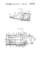
- FIG. 1 is a plan view showing a machine tool holder and the collet of the present invention positioned therein for receiving a cutting tool;
- FIG. 2 is a plan view of the collet of the present invention showing a cutting tool positioned therein and further showing the pathway by which the cutting fluid flows through the collet during the cutting operation;
- FIG. 3 is a perspective view of the collet shown in FIG. 2;
- FIG. 4 is a cross-sectional view of the collet of FIG. 3 taken through line 4--4;
- FIG. 5 is a cross-sectional view of the collet of FIG. 3 taken through line 5--5.
- the collet 2 comprises a forward open end 4 into which is inserted a cutting tool 50 such as a drill bit and a rearward open end 6 which is inserted into a tool holder 54 as shown in FIG. 1 and as described in more detail hereinafter.
- a cutting tool 50 such as a drill bit
- a rearward open end 6 which is inserted into a tool holder 54 as shown in FIG. 1 and as described in more detail hereinafter.
- the collet 2 also includes a collet body 8 having a wall 10 defining a hollow shaft 11 for receiving the cutting tool 50.
- the wall 10 has therein at least one first axial slit 12 and at least one second axial slit 14. As shown in FIGS. 2-5, it is preferred to have a series of alternating first axial slits 12 and second axial slits 14.
- the first axial slits 12 and the second axial slits 14 are connected via a transverse channel 16 to provide a pathway for the flow of a cutting fluid from the rearward open end 6 to the forward open end 4 as indicated by the arrows shown specifically in FIG. 2.
- the collet 2 also has a recess 18 formed between a rim 20 of the collet body 8 and a rim 24 of a neck 22 which runs from the recess 18 to the forward open end 4.
- the neck 22 engages the cutting tool to secure the cutting tool 50 within the collet and the recess 18 anchors the collet within the tool holder 54 as shown in FIG 1.
- the collet body 8 may also contain a grind relief recess 26 which is customarily used to enable the collet 2 to expand or contract around the cutting tool 50 in a known manner to further secure the cutting tool 50 within the collet 2.
- the first axial slits 12 have openings 28 for receiving the cutting fluid from a cutting machine (not shown).
- the openings 28 lead to corresponding pathways 30 which terminate at ends 32 before the forward open end 4.
- the second axial slit 14 open into the forward open end 4 of the collet body 8 at corresponding openings 44 and terminate at corresponding ends 34 before the rearward open end 6 of the collet body 8 to thereby define corresponding pathways 36.
- the second axial slits 14 include openings 38 leading into coaxial slits 40 within the recess 18 which in turn lead into coaxial slits 42 in the neck 22 to thereby form a continuous pathway for the flow of the cutting fluid from the transverse channel 16 through the pathways 36 and out to the workpiece (not shown) via openings 44 in the neck 22.
- the first axial slits 12 are connected to the second axial slits 14 through the transverse channel 16.
- the tranverse channel 16 includes openings 46 for receiving the flow of cutting fluid from the first axial slits 12 and openings 48 leading to the second axial slits 14 so that the cutting fluid can flow into the second axial slits 14 and out the corresponding openings 44.
- the collet 2 is inserted into a corresponding cavity within the tool holder 54 which is insertable into a suitable cutting machine.
- the tool holder 54 includes a retention knob 56 which is inserted into the cutting machine (not shown) to thereby lock the tool holder 54 within the cutting machine.
- the tool holder 54 may also include a frictional clamp 62 to assist in locking the tool holder 54 within the cutting machine.
- An adjuster 58 which may be in the form of a screw lies within the body 59 of the tool holder 54 and is used to adjust the position of the collet 2 to thereby raise or lower the depth of the cutting tool 50 (see FIG. 2) within the collet 2.
- a chuck 60 surrounds the collet 2 in the vicinity of the forward open end 4 to thereby securely lock the cutting tool 50 within the collet 2.
- a channel 64 Running axially through the tool holder 54 and into the rearward open end 6 of the collet 2 is a channel 64 through which the cutting fluid flows from the cutting machine to the collet 2.
- the flow of the cutting fluid through the collet 2 to the workpiece is shown in FIG. 2.
- the cutting fluid enters the rearward open end 6 of the collet 2 from the channel 64 and into the shaft 11 where its path is blocked by the rearward end 52 of the cutting tool 50 (e.g. a drill bit).
- the cutting fluid is forced towards the wall 10 of the collet 2 by the centrifugal force generated by the rotation of the tool holder 54 during the cutting operation.
- the cutting fluid is thus forced to enter the openings 28 of the first axial slits 12 and flows out of the openings 46 into the transverse channel 16.
- the cutting fluid then continues to flow through the transverse channel 16 until it enters the openings 48 of the second axial slits 14.
- the cutting fluid then flows through the pathways 36, through the openings 38 and through the coaxial slits 40 of the recess 18 and the coaxial slits 42 of the neck 22 until the cutting fluid exits from the collet 2 via the openings 44 at the forward open end 4 of the collet body 8 to thereby contact the workpiece.
- the collet 2 may be fashioned with any number of pairs of first 12 and second 14 axial slits so long as there is at least one first axial slit 12 connected to at least one second axial slit 14 via the transverse channel 16.
- the number of second axial slits 14 determines the number of pathways for the flow of the cutting fluid to the workpiece since only the second axial slits 14 open into the forward open end 4 of the collet 2.
- the collet 2 may have more than one consecutive first 12 and/or second 14 axial slit. All that is required is that the cutting fluid be able to flow from the first axial slits 12 to the second axial slits 14 so that there is a continuous pathway for the flow of the cutting fluid from the rearward open end 6 through the collet 2 and out the forward open end 4 to thereby contact the workpiece.
Landscapes
- Engineering & Computer Science (AREA)
- Mechanical Engineering (AREA)
- Gripping On Spindles (AREA)
- Auxiliary Devices For Machine Tools (AREA)
Abstract
Description
Claims (6)
Priority Applications (1)
| Application Number | Priority Date | Filing Date | Title |
|---|---|---|---|
| US06/862,612 US4705439A (en) | 1986-05-12 | 1986-05-12 | Machine tool collet containing means for passing a cutting fluid therethrough |
Applications Claiming Priority (1)
| Application Number | Priority Date | Filing Date | Title |
|---|---|---|---|
| US06/862,612 US4705439A (en) | 1986-05-12 | 1986-05-12 | Machine tool collet containing means for passing a cutting fluid therethrough |
Publications (1)
| Publication Number | Publication Date |
|---|---|
| US4705439A true US4705439A (en) | 1987-11-10 |
Family
ID=25338852
Family Applications (1)
| Application Number | Title | Priority Date | Filing Date |
|---|---|---|---|
| US06/862,612 Expired - Fee Related US4705439A (en) | 1986-05-12 | 1986-05-12 | Machine tool collet containing means for passing a cutting fluid therethrough |
Country Status (1)
| Country | Link |
|---|---|
| US (1) | US4705439A (en) |
Cited By (15)
| Publication number | Priority date | Publication date | Assignee | Title |
|---|---|---|---|---|
| FR2627412A1 (en) * | 1988-02-19 | 1989-08-25 | Engineers Tool Manufacturing C | IMPROVEMENT OF CLAMP SLEEVES |
| US4955764A (en) * | 1987-03-26 | 1990-09-11 | Gottlieb Guhring Kg | Boring tool cooled from within made of a tool spiral and a clamping cylinder |
| US5085540A (en) * | 1990-03-21 | 1992-02-04 | Grumman Aerospace Corporation | Endmill with notched shank |
| FR2695341A1 (en) * | 1992-09-10 | 1994-03-11 | Nikken Kosakusho Works Ltd | Device for supplying a fluid to a machining tool. |
| WO1994027771A1 (en) * | 1993-05-27 | 1994-12-08 | Power Tool Holders, Inc. | Sealing collet |
| US5405220A (en) * | 1993-03-30 | 1995-04-11 | Nt Tool Kabushikikaisha | Oil feeding collet chuck and its collet |
| US5567093A (en) * | 1995-04-11 | 1996-10-22 | Richmond; Daryl E. | Seal for coolant-fed tools |
| US5941664A (en) * | 1997-09-04 | 1999-08-24 | Kennametal Inc. | Toolholder having impeller-type coolant inducer |
| US6280126B1 (en) * | 1999-09-23 | 2001-08-28 | Aesop, Inc. | Damped tool holder and method |
| GB2401335A (en) * | 2003-05-03 | 2004-11-10 | John Charles Baker | Machine tool chuck provided for receiving a supply of pressurised fluid |
| US20110271804A1 (en) * | 2010-05-04 | 2011-11-10 | Chun-Ta Hsieh | Centre drilling/turning tool holder |
| US20130195576A1 (en) * | 2012-02-01 | 2013-08-01 | Teddy JAFFE | Device and method for rotational speed increasing for machining process |
| WO2014030151A1 (en) * | 2012-08-23 | 2014-02-27 | Iscar Ltd. | Cutting tool lock nut having grooved collet-locking surface and cutting tool incorporating same |
| US10160042B2 (en) | 2014-04-04 | 2018-12-25 | Kennametal Inc. | Reducer sleeve with thru coolant flow and a cutting assembly using such reducer sleeve |
| US20190160551A1 (en) * | 2017-11-27 | 2019-05-30 | Kennametal Inc. | Expansion sleeves and associated chucks |
Citations (3)
| Publication number | Priority date | Publication date | Assignee | Title |
|---|---|---|---|---|
| US2889150A (en) * | 1958-06-12 | 1959-06-02 | Modernair Corp | Collet chuck |
| EP0013645A1 (en) * | 1979-01-09 | 1980-07-23 | The Bendix Corporation | Collet for a collet chuck assembly |
| US4570952A (en) * | 1984-05-25 | 1986-02-18 | Thomas Heimbigner | Fluid collet chuck |
-
1986
- 1986-05-12 US US06/862,612 patent/US4705439A/en not_active Expired - Fee Related
Patent Citations (3)
| Publication number | Priority date | Publication date | Assignee | Title |
|---|---|---|---|---|
| US2889150A (en) * | 1958-06-12 | 1959-06-02 | Modernair Corp | Collet chuck |
| EP0013645A1 (en) * | 1979-01-09 | 1980-07-23 | The Bendix Corporation | Collet for a collet chuck assembly |
| US4570952A (en) * | 1984-05-25 | 1986-02-18 | Thomas Heimbigner | Fluid collet chuck |
Cited By (24)
| Publication number | Priority date | Publication date | Assignee | Title |
|---|---|---|---|---|
| US4955764A (en) * | 1987-03-26 | 1990-09-11 | Gottlieb Guhring Kg | Boring tool cooled from within made of a tool spiral and a clamping cylinder |
| FR2627412A1 (en) * | 1988-02-19 | 1989-08-25 | Engineers Tool Manufacturing C | IMPROVEMENT OF CLAMP SLEEVES |
| BE1002833A3 (en) * | 1988-02-19 | 1991-06-25 | Etm Engineers Tool Mfg Company | IMPROVEMENT OF TIGHTENING SOCKETS. |
| US5085540A (en) * | 1990-03-21 | 1992-02-04 | Grumman Aerospace Corporation | Endmill with notched shank |
| FR2695341A1 (en) * | 1992-09-10 | 1994-03-11 | Nikken Kosakusho Works Ltd | Device for supplying a fluid to a machining tool. |
| US5405220A (en) * | 1993-03-30 | 1995-04-11 | Nt Tool Kabushikikaisha | Oil feeding collet chuck and its collet |
| WO1994027771A1 (en) * | 1993-05-27 | 1994-12-08 | Power Tool Holders, Inc. | Sealing collet |
| US5567093A (en) * | 1995-04-11 | 1996-10-22 | Richmond; Daryl E. | Seal for coolant-fed tools |
| US5941664A (en) * | 1997-09-04 | 1999-08-24 | Kennametal Inc. | Toolholder having impeller-type coolant inducer |
| US6280126B1 (en) * | 1999-09-23 | 2001-08-28 | Aesop, Inc. | Damped tool holder and method |
| GB2401335A (en) * | 2003-05-03 | 2004-11-10 | John Charles Baker | Machine tool chuck provided for receiving a supply of pressurised fluid |
| GB2401335B (en) * | 2003-05-03 | 2005-03-30 | John Charles Baker | Machine tool chuck |
| US20110271804A1 (en) * | 2010-05-04 | 2011-11-10 | Chun-Ta Hsieh | Centre drilling/turning tool holder |
| US20130195576A1 (en) * | 2012-02-01 | 2013-08-01 | Teddy JAFFE | Device and method for rotational speed increasing for machining process |
| KR20130089210A (en) * | 2012-02-01 | 2013-08-09 | 갤 웨이 리미티드 | Device and method for rotational speed increasing for machining process |
| JP2013158907A (en) * | 2012-02-01 | 2013-08-19 | Gal Way Ltd | Device and method for increasing rotating speed in machining process |
| US9381606B2 (en) * | 2012-02-01 | 2016-07-05 | Gal Way Ltd. | Device and method for rotational speed increasing for machining process |
| RU2621091C2 (en) * | 2012-02-01 | 2017-05-31 | Гэл Вэй Лтд. | Machine spindle unit |
| WO2014030151A1 (en) * | 2012-08-23 | 2014-02-27 | Iscar Ltd. | Cutting tool lock nut having grooved collet-locking surface and cutting tool incorporating same |
| US9022393B2 (en) | 2012-08-23 | 2015-05-05 | Iscar, Ltd. | Cutting tool lock nut having grooved collet-locking surface and cutting tool incorporating same |
| US10160042B2 (en) | 2014-04-04 | 2018-12-25 | Kennametal Inc. | Reducer sleeve with thru coolant flow and a cutting assembly using such reducer sleeve |
| US10252346B2 (en) | 2014-04-04 | 2019-04-09 | Kennametal Inc. | Reducer sleeve with thru coolant flow and a cutting assembly using such reducer sleeve |
| US20190160551A1 (en) * | 2017-11-27 | 2019-05-30 | Kennametal Inc. | Expansion sleeves and associated chucks |
| US10543538B2 (en) * | 2017-11-27 | 2020-01-28 | Kennametal Inc. | Expansion sleeves and associated chucks |
Similar Documents
| Publication | Publication Date | Title |
|---|---|---|
| US4705439A (en) | Machine tool collet containing means for passing a cutting fluid therethrough | |
| KR100298065B1 (en) | Tool holders and methods for mounting cutting tools in these tool holders | |
| US4863323A (en) | Changing and chucking tool | |
| KR200145569Y1 (en) | Device for supplying fluid tool | |
| US5290135A (en) | Rotary ring cutter having coolant distribution and discharge means | |
| US3364800A (en) | Mist coolant spade drill | |
| KR920005111B1 (en) | Tool holder for drilling and chiselling tools | |
| US4705435A (en) | Reamer | |
| WO2007116620A1 (en) | Deep hole drilling machine | |
| US5028178A (en) | Spring collets | |
| EP0015248B1 (en) | Mounting device for rotary-cutter tools | |
| US10040129B2 (en) | Tool head having a shrink-fit chuck | |
| JP2008506540A (en) | Tool adapter | |
| EP0224770A3 (en) | Quick-change clamping device | |
| US4726717A (en) | Deep-bore drilling machine | |
| US11014177B2 (en) | Whirling device | |
| AU731482B2 (en) | Toolholder having impeller-type coolant inducer | |
| EP0751843B1 (en) | Device for cooling a machine tool retained in a revolver plate | |
| US7357607B2 (en) | Tool holder | |
| JPH04360710A (en) | Tool holder assembly having filler device | |
| US5655855A (en) | Tool for precise machining of metal | |
| GB1487183A (en) | Boring heads | |
| US4274314A (en) | Clamping device | |
| JPH0717452U (en) | Tool holder with coolant outlet | |
| JP2620255B2 (en) | Internal machining tools |
Legal Events
| Date | Code | Title | Description |
|---|---|---|---|
| AS | Assignment |
Owner name: GENERAL ELECTRIC COMPANY, A CORP. OF NEW YORK Free format text: ASSIGNMENT OF ASSIGNORS INTEREST.;ASSIGNORS:HOYLE, WILLIAM;GRAVES, JAMMIE;REEL/FRAME:004583/0881 Effective date: 19860616 Owner name: GENERAL ELECTRIC COMPANY, A CORP. OF NEW YORK,NEW Free format text: ASSIGNMENT OF ASSIGNORS INTEREST;ASSIGNORS:HOYLE, WILLIAM;GRAVES, JAMMIE;REEL/FRAME:004583/0881 Effective date: 19860616 |
|
| AS | Assignment |
Owner name: CARBOLOY INC., A DE. CORP. Free format text: ASSIGNMENT OF ASSIGNORS INTEREST.;ASSIGNOR:GENERAL ELECTRIC COMPANY;REEL/FRAME:004811/0365 Effective date: 19870925 |
|
| FEPP | Fee payment procedure |
Free format text: PAYOR NUMBER ASSIGNED (ORIGINAL EVENT CODE: ASPN); ENTITY STATUS OF PATENT OWNER: LARGE ENTITY |
|
| REMI | Maintenance fee reminder mailed | ||
| LAPS | Lapse for failure to pay maintenance fees | ||
| FP | Lapsed due to failure to pay maintenance fee |
Effective date: 19911110 |
|
| STCH | Information on status: patent discontinuation |
Free format text: PATENT EXPIRED DUE TO NONPAYMENT OF MAINTENANCE FEES UNDER 37 CFR 1.362 |