US4719585A - Dividing cubes system and method for the display of surface structures contained within the interior region of a solid body - Google Patents
Dividing cubes system and method for the display of surface structures contained within the interior region of a solid body Download PDFInfo
- Publication number
- US4719585A US4719585A US06/770,164 US77016485A US4719585A US 4719585 A US4719585 A US 4719585A US 77016485 A US77016485 A US 77016485A US 4719585 A US4719585 A US 4719585A
- Authority
- US
- United States
- Prior art keywords
- locations
- grid
- dimensional
- grid locations
- values
- Prior art date
- Legal status (The legal status is an assumption and is not a legal conclusion. Google has not performed a legal analysis and makes no representation as to the accuracy of the status listed.)
- Expired - Lifetime
Links
Images


Classifications
-
- G—PHYSICS
- G06—COMPUTING; CALCULATING OR COUNTING
- G06T—IMAGE DATA PROCESSING OR GENERATION, IN GENERAL
- G06T17/00—Three dimensional [3D] modelling, e.g. data description of 3D objects
Definitions
- the present invention is generally directed to a system and method for displaying surface information.
- the images of the surfaces displayed are typically contained within the interior regions of solid bodies which are examined by computed tomographic (CT) x-ray systems or by magnetic resonance (MR) imaging systems either of which is capable of generating three dimensional arrays of data representative of one or more physical properties at various locations within a three dimensional volume.
- CT computed tomographic
- MR magnetic resonance
- the present invention is directed to a system and method for the display of medical images so as to obtain representations of internal bodily structures.
- the images generated in the practice of the present invention provide three dimensional data for examination by physicians, radiologists and other medical practitioners.
- CT systems In conventional x-ray systems, a two dimensional shadow image is created based upon the different absorption characteristics of bone and soft tissues.
- a great improvement on the conventional x-ray systems as a diagnostic tool has been provided by computed tomographic systems which have been developed over the last ten years or so.
- These so called CT systems are x-ray based and initially were used to produce single two dimensional views depicting transverse slices of a body, object, or patient being investigated. Three dimensional information was thereafter gleaned from CT scan data by generating data for a number of contiguous slices and using the inferential abilities of the radiologist to suggest a three dimensional representation for the various internal organs.
- shaded and contoured three dimensional images are generated from the three dimensional array of data generated by a sequence of such contiguous CT scans.
- the newer MR imaging technology is also capable of generating three dimensional arrays of data representing physical properties of interior bodily organs.
- MR systems have the capability to better discriminate between various tissue types, not just bone and soft tissue.
- MR imaging systems are also capable of generating physiological data rather than just image data.
- the data has been made available only as a sequence of the slices and systems have not generally been available which provide true three dimensional images.
- three dimensional data generated either by a CT scanning system or by an MR imaging system may be displayed and analyzed in a plurality of ways so as to produce on a display screen or other device, a multitude of anatomical features which are selectable at the viewer's choice.
- the data used to produce the three dimensional images is typically acquired once and then used and re-used to generate information and to display images at the option of the viewer.
- the viewer is provided with the option of selecting one or more threshhold values which determine, for example, whether or not bone surfaces as opposed to brain surface tissue is to be displayed.
- the viewer or operator of the present system can also select the appropriate viewing angle and can, at will, selectively ignore segments of the data generated in order to provide cross sectional views through any desired plane.
- the viewing angle is selectable and it is possible to generate a sequence of images and display them sequentially to provide the medical practitioner with interior views of solid surfaces in a truly three dimensional manner from any desired viewing angle with the further capability of being able to construct a view through any plane or slice.
- the system and method of the present invention provide the medical practitioners, and surgeons in particular, with the ability to plan detailed and complicated surgical procedures using totally non-invasive diagnostic methods.
- the images generated by the present invention can only be described as truly dramatic and show every evidence of being as great an improvement in the medical imaging arts as computed axial tomography and magnetic resonance imaging.
- system and method of the present invention will undoubtedly find its greatest utilization in the analysis and display of tomographic x-ray and magnetic resonance imaging data
- system of the present invention is equally applicable to systems employing ultrasound, positron emission tomography, emission computed tomography and multi-modality imaging.
- present invention is particularly applicable to the construction of medical images
- system and method of the present invention is applicable to the display of interior three dimensional surface structures for any system which is capable of generating three dimensional data arrays in which signal patterns are present which represent the value of at least one physical property associated with points in a solid body.
- a particular advantage of the present invention is its ability to provide the medical practitioner with the means to perform interactive functions in real time.
- Systems which do not permit interactive use suffer a significant disadvantage since a real time display methodology is required for optimal human interaction with the system, particularly in the case of a surgeon planning a difficult procedure.
- the implant comprises human tissue or a mechanical device. It is therefore seen that it would be very important for a surgeon to be able to display the cavity in question on a screen in three dimensional form and be able to rotate it and section it at will, before any invasive procedure is undertaken.
- the images generated are sharp and exhibit excellent contrast. The images generated should also depict surface texture wherever this is possible.
- the display of three dimensional graphic images on a cathode ray tube (CRT) screen has principally been driven by the goals and directions of computer aided design (CAD) and computer aided manufacturing (CAM).
- CAD computer aided design
- CAM computer aided manufacturing
- Systems have been developed for displaying solid bodies and for manipulating images in various fashions to create solid models for manufactured parts and for rotating and viewing these parts from a multiplicity of directions.
- CAD/CAM systems have been developed which accept data in two basic formats.
- the display processor is provided with a sequence or list of three dimensional points representative of the end points of line segments. These line segments are joined to represent various surface structures.
- An advantage of these wire frame images is the ability to rapidly rotate the image about various axes to obtain different views.
- the raster format an image is generated on a screen or other display device as a collection of individual picture elements (pixels) whose intensity and color are determinative of the image displayed.
- an electron beam is typically made to scan across a phosphorous screen in horizontal lines which are sequentially "painted" on the screen.
- the system and method of the present invention are more closely related to the raster based format and representation than the so-called vector based method.
- the vector based/polygonal approaches described in application Ser. No. 741,390 filed June 5, 1985 and application Ser. No. 741,391 filed June 5, 1985 by one or more of the present inventors, said applications being assigned to the same assignee, are particularly accurate in their representation of surface detail.
- the polygonal resolution was in general not related to the resolution of the screen on which the image was displayed.
- a particular advantage of the present invention is that, by subdivision and interpolation, 3-D images may be generated with a resolution which closely matches the resolution of the screen. This resolution is typically measured in dots or pixels per inch.
- screen resolution may be expressed in terms of dot pitch with typical high resolution screens having a dot pitch of approximately 0.3 dots per millimeter in current devices.
- the raster format is particularly useful for displaying images which are more closely related to images as perceived by the human eye, as opposed to wire frame images.
- Meagher working for Phoenix Data Systems, has employed a method of octree coding in which the three dimensional data array is subdivided into eight regions and each region is subdivided until individual volume elements are formed. Regions not containing surfaces are not subdivided.
- this method requires special purpose hardware. While the images are crisp, individual volume elements produce a quantized artifact that is not observed in smooth tissues such as bone.
- Other methods for displaying three dimensional data are, for example, described in U.S. Pat. No. 4,475,104 issued Oct. 2, 1984 in the name of Tsu Y. Shen. This patent appears to disclose a three dimensional display system which incorporates a depth buffer to provide separate 3D information as part of the mechanism for generating appropriate shading values.
- Another object of the present invention is the generation and display of three dimensional raster format based information.
- Still another object of the present invention is to maximize the information contained in a three dimensional data array for the purpose of surface representation.
- a system for displaying three dimensional surface structures comprises means for storing three dimensional signal patterns which represent the value of at least one physical property which is associated with a three dimensional body at regularly spaced grid locations defining the volume elements within the body.
- the system includes means for retrieving the thirty-two three dimensional signal pattern values which are associated with each set of eight cubically adjacent grid locations. These include the twenty-four additional grid locations which are adjacent to the eight cube vertices with each of the cube vertices being associated with three additional grid locations.
- the term "cubically adjacent" refers to grid locations which exist at the eight corners or vertices of a cube, or more generally, parallelopiped.
- the system also includes means for comparing the signal values associated with the eight adjacent grid locations, which define a volume element or voxel, with a predetermined threshhold value to determine those volume elements for which at least one of the eight comparisons results in a value distinct from the other seven comparisons.
- This first comparison operation acts to identify and select those volume elements through which the desired surface passes.
- the surface itself is determined by the threshhold value and is selectable by the user.
- the system also includes first means for generating normal vectors from the thirty-two signal pattern values associated with each voxel element. It is these normal vectors in concert with a user selectable viewing angle (elevation and rotation), that determines shading for the image displayed.
- Second generating means are also provided for generating, for each selected volume element, a plurality of additional signal values associated with additional spacial locations defined along the edges and within the interior of the selected volume elements.
- this generating means subdivides the volume element and increases the resolution and smoothness of the resulting image.
- the subdivision of the volume preferably, though not exclusively, employs a factor of 2 or a power thereof to perform the necessary subdivision.
- This generating means is an important aspect of the present invention since it permits the construction of images in which the physical resolution of the data collected is closely matched to the pixel resolution on the display device. This is a very desirable feature of the present invention since it permits optimal use of the data available in terms of the display device being employed. It is also particularly advantageous in that it facilitates zooming and enlargement operations.
- the system of the present invention also includes second comparison means for comparing signal values associated with each subdivided voxel element with the same predetermined threshhold value so as to generate a sequence of selected values which identify grid locations and additional spacial locations which at least approximately lie on a surface determined by the threshhold value. Also included is a third means which operates to generate normal vectors which are associated with the above-described additional spacial locations.
- the signal values associated with the additional spacial locations are computed using linear or other interpolation methods. However, linear interpolation has been found to be sufficiently fast and accurate for the method and system disclosed herein.
- the means for generating normal vectors associated with the additionally defined spatial locations also preferably employs linear interpolation.
- the generation means described herein are configured so that originally selected grid locations and additionally selected spacial locations are associated with their corresponding vectors for these locations. Accordingly, in accordance with one embodiment of the present invention, the output signal produced is representative of grid coordinate locations for points selected to lie on a given surface, these points being associated with normal vectors which are employed by a display processing system to produce the desired image.
- display processing systems receive information in formats that are well known to those skilled in the electronic graphic display arts. Such systems employ normal vector information to determine the desired degree of shading and/or color which is applied to each pixel location.
- a method for carrying out the above-identified storage retrieval generation and comparison operations is also disclosed herein.
- a discriminating threshhold value or range of values may be chosen so as to selectively view various body structures. For example, if one wishes to view bony structures, a particular threshhold value is chosen. However, if one wishes to view the surface structures of softer tissue, a different threshhold value is selected by the operator.
- the system for displaying such three dimensional surface structures should include accurate means for determining local surface normal directions, since it is these directions which greatly enhance the ability of the viewer to recognize the shading clues for a truly three dimensional representation.
- FIG. 1 is a perspective view illustrating a single voxel element defined by 8 grid locations and surrounded by twenty-four additional data points;
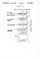
- FIG. 2 is a schematic diagram illustrating both the apparatus and method of the present invention
- FIG. 3 is a schematic diagram more particularly illustrating various functionalities which may be employed in a display processor used in the present invention
- FIG. 4 is a perspective view illustrating surface normal vectors associated with each voxel vertex
- FIG. 5 is a perspective view similar to FIG. 4 more particularly illustrating the generation of additional normal vectors associated with a subdivided voxel
- FIG. 6 is a perspective view similar to FIG. 4 which particularly illustrates the fact that subdivision operations may be performed in such a way as to divide the volume element into differently sized subelements along distinct grid axis directions;
- FIG. 7 is a photograph illustrating a medical application of the present invention in which it is seen that both skin and bone threshhold values may be selected for different portions of the data display.
- a sequence of voxel elements is examined.
- data from four consecutive MR or CT scan slices is analyzed at a time.
- FIG. 1 illustrates a single voxel element with vertices V1 through V8 as shown.
- Each voxel element naturally spans two slices of image information.
- a signal pattern value which represents a measurement of at least one physical property which is associated with a three dimensional body at regularly spaced grid locations within the body. The grid locations define volume elements or voxels.
- each voxel vertex V1 through V8 is also associated with three adjacent grid locations. These adjacent grid locations are the ones which lie along grid coordinate lines and which are not specifically included in the voxel itself. There are twenty-four such data points. For example, it is seen that vertex V1 is associated with grid locations W1, W5, and W12. In a similar fashion, vertex location V7 is associated with grid locations W16, W17, and W23. These other, additional grid locations are shown as open circles in FIG. 1. The voxel grid locations themselves are shown as filled-in circles. It is therefore seen that each voxel vertex grid location is associated with three adjacent grid locations. In FIG.
- these additional grid locations are labeled as W1 through W24, as shown. It is therefore seen that these additional grid locations are twenty-four in number and occupy 4 data slices.
- the data values at these additional grid locations are employed, along with the data values at the voxel vertex locations, to generate data value triplets which represent normal vectors associated with each vertex point V1 through V8.
- the various normal vector components are computed using finite difference methods, a central difference in particular. For example, to compute the x component of the normal vector at vertex V1, data values at vertex V4 and grid location W5 are differenced.
- the z component of the normal vector associated with vertex V1 is similarly computed using data values at grid locations V5 and W1.
- the y component of the normal vector associated with vertex V1 is generated using the data values associated with grid locations V2 and W12.
- the order in which the difference is taken is naturally selected to be consistent with the orientation of some coordinate system (see axes) and the method is employed uniformly throughout for the other voxels. In this manner, it is seen how data from 4 slices is employed to generate normal vectors associated with each voxel vertex location. The resulting vector formed from differences is then scaled to unit magnitude.
- FIG. 2 illustrates, in schematic form, a flow chart and hardware description of a system in accordance with the present invention.
- three dimensional signal data is provided from an MR or CT scan system 10.
- This data is typically stored in an appropriate storage system 15.
- this storage system comprises some form of magnetic storage medium such as a floppy disk, hard disk drive, or tape.
- the data is organized in a format which permits associating each physical measurement representation with a corresponding grid location associated with that measurement.
- each slice buffer 20 includes layers No. 1, No. 2, No. 3, and No. 4, with each memory layer containing representations for the signal pattern values at the various grid locations. Each layer preferably contains the data for an entire two dimensional slice of the body being imaged.
- a slice scanner is employed so as to scan through the data along one of the axis directions. In the preferred embodiments of the present invention, there is a direct correlation between buffer address values and the grid locations within the body. It should be borne in mind that as one scans through the data in one axis direction by means of the slice scanner, it is only necessary to retrieve a single additional slice of information at a time.
- the scanner can be made to operate in a fashion so that only data from a single image plane need be retrieved at one time.
- additional scanning is performed throughout layers No. 2 and No. 3 of buffer 20. It is these intermediate layers which contain grid locations at voxel vertices.
- Four signals values from one voxel face are provided from layer 2 and at the same time, four signal values from layer 3 are similarly provided to voxel register 25.
- the four signal values from layer No. 3 correspond to the four vertices opposite the voxel slice selected from layer No. 2.
- each voxel element is defined by four grid locations from layer No. 2 and four grid locations from layer No. 3 of buffer 20.
- the operation of the present invention proceeds from voxel to voxel by means of scanning operations carried out in layers No. 2 and No. 3.
- voxel register 25 Corresponding to the selection of each voxel element, a total of eight values is therefore supplied to voxel register 25.
- twenty-four additional measurements are provided to voxel neighbor register 30. Dotted lines are shown connecting registers 25 and 30 to indicate that in practice, these registers might actually comprise a single thirty-two cell register. Each cell in the register contains the corresponding physical measurement in an appropriate and consistent representational format. In this way, for each voxel element, the values associated with vertices V1 through V8 are supplied to register 25. In a like fashion, the physical measurement values associated with additional grid locations W1 through W24 are supplied to register 30.
- Comparator 35 operates to compare each of the eight values supplied with a user supplied threshhold value. If all eight of the comparison results are the same, then it is clear that the surface selected by the threshhold does not pass through the particular voxel being analyzed. In this case, the enable line inhibits output generation for that voxel. If any of the comparisons generated by comparator 35 are different than the other comparisons, then normal vector generation is enabled. The generation of normal vectors is accomplished in functional block 40 which is provided with the eight signal values from voxel register 25 and the twenty-four signal values from neighbor register 30.
- normal generator 40 When enabled for a given voxel element, normal generator 40 operates to produce eight normal vectors associated with vertices V1-V8. This normal generation is accomplished by the differencing method described above. Although it is not necessary at this point in the process, normal generator 40 may also operate to adjust the magnitude of the normal vectors generated so that each possesses a unit magnitude.
- divider/interpolator 45 An important function of the present invention is provided by divider/interpolator 45. This operation is also enabled by the results of comparator 35. In particular, when a voxel is found which contains a segment of the surface defined by the threshhold value, additional operations are enabled. These additional operations generate additional data values associated with additional grid locations within a selected voxel element. Additionally, normal vectors are also generated for each additional grid location constructed by voxel subdivision and interpolation. For example, functional block 45 operates upon the eight signal values from register 25 to produce a set of additional interpolated measurement values, preferably by linear interpolation.
- the grid location midway between two voxel vertices may be assigned a measurement value equal to one half the sum of the measurement values at the two adjacent voxel locations.
- a grid location which lies in the middle of a voxel face may be assigned a measurement value which is equal to one fourth of the sum of the measurement values assigned to each of the vertex grid locations associated with that face.
- a grid location contained within the center of the voxel may be assigned a measurement value which is equal to one eighth of the sum of the measurement values associated with all eight of the voxel data values.
- normal generator 50 produces normal vectors associated with each of the grid locations for the subdivided voxels. For example, the normal vectors associated with an edge point between two voxel vertices is generated as one half of the vector sum of the normal vectors associated with that particular edge. Analogous results are generated for additional normal vectors associated with cube faces and interiors.
- Functional block 50 also preferably operates to scale each of the normal vectors generated to fix the magnitude of each vector generated at unity.
- Custom integrated circuit chips are available for performing such square root operations necessary for magnitude normalization of the normal vectors generated. (Note though that here normalization is used in two different senses, one to describe the magnitude of the vector and another to indicate that the vector is at least approximately normal to the surface determined by the threshhold value.) Accordingly, for each voxel selected as a result of the comparison performed by comparator 35, divider/interpolator 45 produces a set of interpolated measurement values corresponding to a more finely divided voxel element.
- normal generator 50 provides signal values representing normal vectors occurring at voxel vertices and also at intermediate and internal grid locations. For each selected voxel element, there is a fixed number of sub-voxel elements generated. As suggested by the double ended horizontal arrow between divider/interpolator 45 and comparator 55 each sub-voxel is scanned and compared with the same threshhold value as above. This comparison operation is performed by comparator 55 for each sub-voxel element. The comparison operation is essentially the same as that described above.
- divider/interpolator 45 also employs slice and voxel scanner data to penetrate x, y, and z location values to be associated with each normal vector in register 60. Accordingly, register 60 contains grid locations along the x, y, and z axes and normal vector components corresponding to the surface normal vector at that location. It is this information which is supplied to a conventional display processor.
- FIG. 3 illustrates a substantially conventional display processor which receives positional and normal vector information. This enables the processor to generate pixel information on a screen with appropriate shading. For example, the user may supply a view angle and view elevation as part of a matrix multiplication function performed by block 70. Likewise, as in conventional display processing systems, a clip plane may be selected to effectively eliminate data points on one side thereof. This is useful is generating cross-sectional images. This function is carried out in block 75.
- buffer(s) 80 it is possible to store overlapping images in one or more frame buffers, such as buffer(s) 80.
- One of these buffer may be provided with information based upon a particular threshhold value, say for example, the threshhold value determined by skin with the contents of another frame buffer being loaded with image data developed from a different threshhold value, say that value associated with bone.
- This enables information to be displayed concurrently or may in fact enable part of the display to depict one tissue type and another part of the display to depict a second tissue type.
- a shading control may also be provided by means of lookup table 85 (LUT) which serves to select colors (red, green, blue) for each pixel displayed depending upon position, tissue type (threshhold) and normal vector information.
- the pixels are displayed on monitor 90. While the display processor portion of the present invention comprises conventional and well known hardware elements, these elements are configured to cooperatively interact with the selection of a threshhold value and various other selectable parameters, as indicated in FIG
- the image is produced by calculating the intensity from the component of the normal that is perpendicular to the viewing plane.
- Hidden surfaces are removed by the painter's algorithm, that is, the more distance surfaces are painted over by the closer surfaces as the image is scanned from front to back.
- six views of the three dimensional image may be produced.
- the operations of testing, subdividing, and finding the normal may be implemented rapidly with special purpose hardware which is well known in the electronic graphics arts.
- FIG. 4 illustrates a single voxel with vertices V1-V8.
- a normal vector is defined. In accordance with the method of the present invention, however, only certain vertices or grid locations are selected. Each selected vertex is, however, always associated with a normal vector.
- Each voxel element includes edges E1-E12, as shown. Additionally, each voxel element includes faces F1-F6, as shown. More particularly, with respect to the present invention, each selected voxel element is subdivided in the direction of the three axes corresponding to the various grid locations. For example, FIG. 5 illustrates a subdivision in which each voxel edge is divided into two equal parts by an intermediate point.
- edge E1 includes intermediate point U1 and a computed normal vector associated therewith.
- face F2 includes facially centered point S2 and a normal vector associated therewith.
- the normal vectors or points, S1-S6 corresponding to faces F1-F6.
- additional vectors are defined at points U1-U12 corresponding to edges E1-E12.
- an additional interior point (not shown) is also defined and associated with a normal vector which is generated as an arithmetic average of adjacent vectors.
- the single voxel shown in FIG. 4 is subdivided into eight subvoxel elements in FIG.
- FIG. 6 illustrates the fact that voxel subdivisions may be made in any practical integer number of subdivisions. Moreover, each coordinate direction may involve a different number of subdivisions. This is particularly useful in situations in which resolution is not identical in all directions. For the case shown in FIG. 6, twenty-four subdivisions are made.
- the number of subdivisions made for each voxel is the same throughout the image.
- the number and nature of subdivision may be selectable at the outset of image generation. This is a particularly useful aspect of the present invention in that it enables the operator to more closely match screen resolution monitor 90 with resolution found in the data itself. This is also particularly useful for zooming operations.
- FIG. 7 Graphical images of medical data have been generated in accordance with the invention herein. A particular result of such processing is illustrated in FIG. 7.
- FIG. 7 also illustrates the fact that both skin and bone surfaces may be displayed in the same graphic image.
- FIG. 7 also illustrates the fact that the user may select that portion of the frame which displays one tissue type with another portion of the frame displaying another tissue type.
- the tissue types are skin and bone.
- the method and apparatus of the present invention produces high resolution, three dimensional images from any measurement system which provides measurement of a physical property associated with a three dimensional array of grid locations defined throughout a region being studied. While the above description has primarily been directed at the generation images as they would appear to the human eye, if visible, it is also to be noted that since the system is based upon the measurement of physical properties, some of the images that may be produced might, for example, be representative of the distribution of chemical compounds, for example, as they might be distributed throughout a body. While images of this distribution would not be visible to the human eye, nonetheless, such images are readily generated by the present invention.
- the objects of the present invention have been met particularly in that the screen resolution is readily accommodated by judicious prior selection of an appropriate degree of subdivision processing. It is also seen that the method of the present invention is accomplished rapidly because of the elimination of voxel elements and sub-voxel elements which do not contain surface intersections.
Abstract
Description
Claims (8)
Priority Applications (4)
| Application Number | Priority Date | Filing Date | Title |
|---|---|---|---|
| US06/770,164 US4719585A (en) | 1985-08-28 | 1985-08-28 | Dividing cubes system and method for the display of surface structures contained within the interior region of a solid body |
| JP61192213A JPS6297074A (en) | 1985-08-28 | 1986-08-19 | Method and apparatus for displaying 3-d surface structure |
| DE3689399T DE3689399T2 (en) | 1985-08-28 | 1986-08-22 | Cube division system and method for displaying surface structures contained in the interior of a solid body. |
| EP86111637A EP0216156B1 (en) | 1985-08-28 | 1986-08-22 | Dividing cubes and method for the display of surface structures contained within the interior region of a solid body |
Applications Claiming Priority (1)
| Application Number | Priority Date | Filing Date | Title |
|---|---|---|---|
| US06/770,164 US4719585A (en) | 1985-08-28 | 1985-08-28 | Dividing cubes system and method for the display of surface structures contained within the interior region of a solid body |
Publications (1)
| Publication Number | Publication Date |
|---|---|
| US4719585A true US4719585A (en) | 1988-01-12 |
Family
ID=25087679
Family Applications (1)
| Application Number | Title | Priority Date | Filing Date |
|---|---|---|---|
| US06/770,164 Expired - Lifetime US4719585A (en) | 1985-08-28 | 1985-08-28 | Dividing cubes system and method for the display of surface structures contained within the interior region of a solid body |
Country Status (4)
| Country | Link |
|---|---|
| US (1) | US4719585A (en) |
| EP (1) | EP0216156B1 (en) |
| JP (1) | JPS6297074A (en) |
| DE (1) | DE3689399T2 (en) |
Cited By (132)
| Publication number | Priority date | Publication date | Assignee | Title |
|---|---|---|---|---|
| US4821213A (en) * | 1986-12-19 | 1989-04-11 | General Electric Co. | System for the simultaneous display of two or more internal surfaces within a solid object |
| US4821210A (en) * | 1987-04-02 | 1989-04-11 | General Electric Co. | Fast display of three-dimensional images |
| US4831528A (en) * | 1987-11-09 | 1989-05-16 | General Electric Company | Apparatus and method for improvement of 3D images derived from tomographic data |
| US4855938A (en) * | 1987-10-30 | 1989-08-08 | International Business Machines Corporation | Hidden line removal method with modified depth buffer |
| US4866612A (en) * | 1986-03-05 | 1989-09-12 | Hitachi Medical Corporation | Imaging system including means to provide a display image with shadows and three dimensional perspectives by a combination of voxel and surface method |
| US4868748A (en) * | 1987-11-25 | 1989-09-19 | General Electric Company | Rapid processing of three-dimensional graphical objects from tomographic data |
| US4879668A (en) * | 1986-12-19 | 1989-11-07 | General Electric Company | Method of displaying internal surfaces of three-dimensional medical images |
| US4885688A (en) * | 1987-11-25 | 1989-12-05 | General Electric Company | Minimization of directed points generated in three-dimensional dividing cubes method |
| US4888713A (en) * | 1986-09-05 | 1989-12-19 | Cdi Technologies, Inc. | Surface detail mapping system |
| US4947347A (en) * | 1987-09-18 | 1990-08-07 | Kabushiki Kaisha Toshiba | Depth map generating method and apparatus |
| US4953087A (en) * | 1988-10-24 | 1990-08-28 | General Electric Company | Three-dimensional images obtained from tomographic data having unequally spaced slices |
| US4974175A (en) * | 1987-06-19 | 1990-11-27 | Hitachi, Ltd. | Drawing information processing method and apparatus |
| US4982438A (en) * | 1987-06-02 | 1991-01-01 | Hitachi, Ltd. | Apparatus and method for recognizing three-dimensional shape of object |
| US4984157A (en) * | 1988-09-21 | 1991-01-08 | General Electric Company | System and method for displaying oblique planar cross sections of a solid body using tri-linear interpolation to determine pixel position dataes |
| US4985834A (en) * | 1988-11-22 | 1991-01-15 | General Electric Company | System and method employing pipelined parallel circuit architecture for displaying surface structures of the interior region of a solid body |
| US4987554A (en) * | 1988-08-24 | 1991-01-22 | The Research Foundation Of State University Of New York | Method of converting continuous three-dimensional geometrical representations of polygonal objects into discrete three-dimensional voxel-based representations thereof within a three-dimensional voxel-based system |
| US4992962A (en) * | 1987-04-30 | 1991-02-12 | Hitachi, Ltd. | Area set operation apparatus |
| US4994989A (en) * | 1987-10-09 | 1991-02-19 | Hitachi, Ltd. | Displaying method and apparatus for three-dimensional computer graphics |
| DE4034086A1 (en) * | 1989-10-30 | 1991-05-02 | Gen Electric | Producing data for specimen object - representing as vol. reproduced projection image involving pixel sealing to correct anisotropy |
| US5023811A (en) * | 1988-10-13 | 1991-06-11 | Bell Communications Research, Inc. | Method and apparatus for selectively processing paginated output |
| US5036475A (en) * | 1987-11-02 | 1991-07-30 | Daikin Industries, Ltd. | Image memory data processing control apparatus |
| US5038302A (en) * | 1988-07-26 | 1991-08-06 | The Research Foundation Of State University Of New York | Method of converting continuous three-dimensional geometrical representations into discrete three-dimensional voxel-based representations within a three-dimensional voxel-based system |
| US5084830A (en) * | 1987-10-26 | 1992-01-28 | Tektronix, Inc. | Method and apparatus for hidden surface removal |
| US5095521A (en) * | 1987-04-03 | 1992-03-10 | General Electric Cgr S.A. | Method for the computing and imaging of views of an object |
| US5113490A (en) * | 1989-06-19 | 1992-05-12 | Silicon Graphics, Inc. | Method for forming a computer model from an intersection of a cutting surface with a bounded volume |
| US5123084A (en) * | 1987-12-24 | 1992-06-16 | General Electric Cgr S.A. | Method for the 3d display of octree-encoded objects and device for the application of this method |
| US5166876A (en) * | 1991-01-16 | 1992-11-24 | General Electric Company | System and method for detecting internal structures contained within the interior region of a solid object |
| US5187660A (en) * | 1989-12-01 | 1993-02-16 | At&T Bell Laboratories | Arrangement for displaying on a display volumetric data |
| US5187658A (en) * | 1990-01-17 | 1993-02-16 | General Electric Company | System and method for segmenting internal structures contained within the interior region of a solid object |
| JPH05274446A (en) * | 1991-12-23 | 1993-10-22 | General Electric Co <Ge> | Graphics work station and method for generating three-dimensional graphics picture |
| US5257346A (en) * | 1990-09-24 | 1993-10-26 | International Business Machines Corporation | Wire-mesh generation from image data |
| JPH05282465A (en) * | 1991-12-23 | 1993-10-29 | General Electric Co <Ge> | Graphics work station for handling polygonal model |
| JPH05290174A (en) * | 1991-12-23 | 1993-11-05 | General Electric Co <Ge> | Graphics work station for handling structure of 3-dimensional model and method for generating 3-dimensional graphics picture of structure of model |
| US5333244A (en) * | 1990-11-29 | 1994-07-26 | Hitachi, Ltd. | Method of and system for displaying a scalar quantity distribution |
| US5335317A (en) * | 1990-03-28 | 1994-08-02 | Hitachi, Ltd. | Method and apparatus for displaying three dimensional physical quantity |
| WO1994024640A1 (en) * | 1993-04-13 | 1994-10-27 | Daniel Karron | System and method for surface rendering of internal structures within the interior of a solid object |
| US5379371A (en) * | 1987-10-09 | 1995-01-03 | Hitachi, Ltd. | Displaying method and apparatus for three-dimensional computer graphics |
| US5381518A (en) * | 1986-04-14 | 1995-01-10 | Pixar | Method and apparatus for imaging volume data using voxel values |
| US5398684A (en) * | 1988-12-23 | 1995-03-21 | Hardy; Tyrone L. | Method and apparatus for video presentation from scanner imaging sources |
| US5412563A (en) * | 1993-09-16 | 1995-05-02 | General Electric Company | Gradient image segmentation method |
| US5433199A (en) * | 1994-02-24 | 1995-07-18 | General Electric Company | Cardiac functional analysis method using gradient image segmentation |
| US5488952A (en) * | 1982-02-24 | 1996-02-06 | Schoolman Scientific Corp. | Stereoscopically display three dimensional ultrasound imaging |
| US5517602A (en) * | 1992-12-03 | 1996-05-14 | Hewlett-Packard Company | Method and apparatus for generating a topologically consistent visual representation of a three dimensional surface |
| US5537520A (en) * | 1989-12-12 | 1996-07-16 | International Business Machines Corporation | Method and system for displaying a three dimensional object |
| US5546327A (en) * | 1990-12-27 | 1996-08-13 | Matsushita Electric Industrial Co., Ltd. | Apparatus for calculating geometrical view factor |
| US5555352A (en) * | 1991-04-23 | 1996-09-10 | International Business Machines Corporation | Object-based irregular-grid volume rendering |
| US5568384A (en) * | 1992-10-13 | 1996-10-22 | Mayo Foundation For Medical Education And Research | Biomedical imaging and analysis |
| US5570460A (en) * | 1994-10-21 | 1996-10-29 | International Business Machines Corporation | System and method for volume rendering of finite element models |
| US5590215A (en) * | 1993-10-15 | 1996-12-31 | Allen; George S. | Method for providing medical images |
| US5602891A (en) * | 1995-11-13 | 1997-02-11 | Beth Israel | Imaging apparatus and method with compensation for object motion |
| US5611025A (en) * | 1994-11-23 | 1997-03-11 | General Electric Company | Virtual internal cavity inspection system |
| US5659629A (en) * | 1995-04-07 | 1997-08-19 | General Electric Company | Visualization of a multi-dimensional data set acquired with a surface receive coil |
| WO1998000811A1 (en) * | 1996-06-28 | 1998-01-08 | Resolution Technologies, Inc. | Fly-through computer aided design method and apparatus |
| US5740802A (en) * | 1993-04-20 | 1998-04-21 | General Electric Company | Computer graphic and live video system for enhancing visualization of body structures during surgery |
| US5782762A (en) * | 1994-10-27 | 1998-07-21 | Wake Forest University | Method and system for producing interactive, three-dimensional renderings of selected body organs having hollow lumens to enable simulated movement through the lumen |
| US5821942A (en) * | 1996-03-27 | 1998-10-13 | General Electric Company | Ray tracing through an ordered array |
| US5872902A (en) * | 1993-05-28 | 1999-02-16 | Nihon Unisys, Ltd. | Method and apparatus for rendering of fractional pixel lists for anti-aliasing and transparency |
| US5872571A (en) * | 1996-05-14 | 1999-02-16 | Hewlett-Packard Company | Method and apparatus for display of multi-planar ultrasound images employing image projection techniques |
| US5900880A (en) * | 1996-03-06 | 1999-05-04 | General Electric Company | 3-D surfaces generated from a list of cubic elements |
| US5920319A (en) * | 1994-10-27 | 1999-07-06 | Wake Forest University | Automatic analysis in virtual endoscopy |
| US5946425A (en) * | 1996-06-03 | 1999-08-31 | Massachusetts Institute Of Technology | Method and apparatus for automatic alingment of volumetric images containing common subject matter |
| US6054992A (en) * | 1997-09-19 | 2000-04-25 | Mitsubishi Electric Information Technology Center America, Inc. | cutting, jointing and tearing volumetric objects |
| US6084593A (en) * | 1998-05-14 | 2000-07-04 | Mitsubishi Electric Information Technology Center America, Inc. | Surface net smoothing for surface representation from binary sampled data |
| US6115048A (en) * | 1997-01-21 | 2000-09-05 | General Electric Company | Fast method of creating 3D surfaces by `stretching cubes` |
| US6181348B1 (en) * | 1997-09-22 | 2001-01-30 | Siemens Corporate Research, Inc. | Method for selective volume visualization via texture mapping |
| US6219060B1 (en) | 1998-10-15 | 2001-04-17 | General Electric Company | Rendering of surfaces from volumetric data employing both dividing and stretching cubes |
| US6246784B1 (en) | 1997-08-19 | 2001-06-12 | The United States Of America As Represented By The Department Of Health And Human Services | Method for segmenting medical images and detecting surface anomalies in anatomical structures |
| US6298148B1 (en) | 1999-03-22 | 2001-10-02 | General Electric Company | Method of registering surfaces using curvature |
| US20010031920A1 (en) * | 1999-06-29 | 2001-10-18 | The Research Foundation Of State University Of New York | System and method for performing a three-dimensional virtual examination of objects, such as internal organs |
| US6310477B1 (en) | 1999-05-10 | 2001-10-30 | General Electric Company | MR imaging of lesions and detection of malignant tumors |
| US20020015517A1 (en) * | 2000-03-29 | 2002-02-07 | Hwang Scott N. | Subvoxel processing: a method for reducing partial volume blurring |
| US6369812B1 (en) | 1997-11-26 | 2002-04-09 | Philips Medical Systems, (Cleveland), Inc. | Inter-active viewing system for generating virtual endoscopy studies of medical diagnostic data with a continuous sequence of spherical panoramic views and viewing the studies over networks |
| US20020045153A1 (en) * | 1996-09-16 | 2002-04-18 | Kaufman Arie E. | System and method for performing a three-dimensional virtual segmentation and examination with optical texture mapping |
| US6377865B1 (en) * | 1998-02-11 | 2002-04-23 | Raindrop Geomagic, Inc. | Methods of generating three-dimensional digital models of objects by wrapping point cloud data points |
| US6393314B1 (en) | 1999-05-06 | 2002-05-21 | General Electric Company | RF driven resistive ablation system for use in MRI guided therapy |
| US20020165689A1 (en) * | 2001-04-18 | 2002-11-07 | Callegari Andres C. | Volume body renderer |
| US20020171643A1 (en) * | 2001-04-26 | 2002-11-21 | Ernst Fabian Edgar | Surface generator unit for and method of approximating an implicit surface and image display apparatus comprising the surface generator unit |
| US20020190986A1 (en) * | 2001-06-12 | 2002-12-19 | Minolta Co., Ltd. | Method, apparatus, and computer program for generating three-dimensional shape data or volume data |
| US20030001836A1 (en) * | 2001-03-12 | 2003-01-02 | Ernst Fabian Edgar | Reconstructor for and method of generating a three-dimensional representation and image display apparatus comprising the reconstructor |
| US20030074174A1 (en) * | 2000-10-06 | 2003-04-17 | Ping Fu | Manufacturing methods and systems for rapid production of hearing-aid shells |
| US20030208116A1 (en) * | 2000-06-06 | 2003-11-06 | Zhengrong Liang | Computer aided treatment planning and visualization with image registration and fusion |
| US20040015070A1 (en) * | 2001-02-05 | 2004-01-22 | Zhengrong Liang | Computer aided treatment planning |
| US20040021662A1 (en) * | 2002-07-31 | 2004-02-05 | International Business Machines Corporation | Bi-level iso-surface compression |
| US6694163B1 (en) | 1994-10-27 | 2004-02-17 | Wake Forest University Health Sciences | Method and system for producing interactive, three-dimensional renderings of selected body organs having hollow lumens to enable simulated movement through the lumen |
| US20040064029A1 (en) * | 2002-09-30 | 2004-04-01 | The Government Of The Usa As Represented By The Secretary Of The Dept. Of Health & Human Services | Computer-aided classification of anomalies in anatomical structures |
| US20040070584A1 (en) * | 2000-11-25 | 2004-04-15 | Soon-Hyoung Pyo | 3-dimensional multiplanar reformatting system and method and computer-readable recording medium having 3-dimensional multiplanar reformatting program recorded thereon |
| US20040125103A1 (en) * | 2000-02-25 | 2004-07-01 | Kaufman Arie E. | Apparatus and method for volume processing and rendering |
| US20050010097A1 (en) * | 2003-06-26 | 2005-01-13 | Cline Harvey E. | System and method for measuring fluid volumes in brain images |
| US20050015173A1 (en) * | 2001-08-16 | 2005-01-20 | Hitoshi Ohmori | Rapid prototyping method and device using v-cad data |
| US6853373B2 (en) | 2001-04-25 | 2005-02-08 | Raindrop Geomagic, Inc. | Methods, apparatus and computer program products for modeling three-dimensional colored objects |
| US20050035979A1 (en) * | 1998-05-20 | 2005-02-17 | Kabushiki Kaisha Sega Enterprises | Image processing unit, game machine, image processing method, and recording medium |
| US20050075847A1 (en) * | 2001-07-11 | 2005-04-07 | Tomonori Yamada | Method for storing entity data in which shape and physical quantity are integrated and storing program |
| US20050114831A1 (en) * | 2001-04-18 | 2005-05-26 | Andres Callegari | Volume body renderer |
| US20050216238A1 (en) * | 2002-02-28 | 2005-09-29 | Riken | Method and program for converting boundary data into cell inner shape data |
| US6996505B1 (en) | 2000-06-21 | 2006-02-07 | Raindrop Geomagic, Inc. | Methods, apparatus and computer program products for automatically generating nurbs models of triangulated surfaces using homeomorphisms |
| US20060066614A1 (en) * | 2004-09-28 | 2006-03-30 | Oliver Grau | Method and system for providing a volumetric representation of a three-dimensional object |
| US20070038070A1 (en) * | 2003-10-07 | 2007-02-15 | Martin Tank | Determining patient-related information on the position and orientation of MR images by the individualisation of a body model |
| US20070040833A1 (en) * | 2003-08-18 | 2007-02-22 | George Buyanovski | Method and system for adaptive maximum intensity projection ray casting |
| US7190328B1 (en) | 2004-05-07 | 2007-03-13 | James Clar | Three-dimensional display |
| US20070103464A1 (en) * | 1999-06-29 | 2007-05-10 | Kaufman Arie E | System and method for performing a three-dimensional virtual examination of objects, such as internal organs |
| US7324104B1 (en) | 2001-09-14 | 2008-01-29 | The Research Foundation Of State University Of New York | Method of centerline generation in virtual objects |
| US7333104B2 (en) | 2001-12-04 | 2008-02-19 | Riken | Method and program of converting three-dimensional shape data into cell internal data |
| US7372460B2 (en) | 2003-07-16 | 2008-05-13 | Riken | Method and program for generating volume data from boundary representation data |
| US20080147072A1 (en) * | 2006-12-18 | 2008-06-19 | Ilwhan Park | Arthroplasty devices and related methods |
| US20090110498A1 (en) * | 2007-10-25 | 2009-04-30 | Ilwhan Park | Arthroplasty systems and devices, and related methods |
| US20090131941A1 (en) * | 2002-05-15 | 2009-05-21 | Ilwhan Park | Total joint arthroplasty system |
| US20090138020A1 (en) * | 2007-11-27 | 2009-05-28 | Otismed Corporation | Generating mri images usable for the creation of 3d bone models employed to make customized arthroplasty jigs |
| US7574024B2 (en) | 2000-10-02 | 2009-08-11 | The Research Foundation Of State University Of New York | Centerline and tree branch skeleton determination for virtual objects |
| US20090222015A1 (en) * | 2008-02-29 | 2009-09-03 | Otismed Corporation | Hip resurfacing surgical guide tool |
| US7596256B1 (en) | 2001-09-14 | 2009-09-29 | The Research Foundation For The State University Of New York | Computer assisted detection of lesions in volumetric medical images |
| US20090303507A1 (en) * | 2008-06-06 | 2009-12-10 | Virginia Venture Industries, Llc | Methods and apparatuses for printing three dimensional images |
| US20100023015A1 (en) * | 2008-07-23 | 2010-01-28 | Otismed Corporation | System and method for manufacturing arthroplasty jigs having improved mating accuracy |
| US20100042105A1 (en) * | 2007-12-18 | 2010-02-18 | Otismed Corporation | Arthroplasty system and related methods |
| US20100152741A1 (en) * | 2008-12-16 | 2010-06-17 | Otismed Corporation | Unicompartmental customized arthroplasty cutting jigs and methods of making the same |
| US7747055B1 (en) | 1998-11-25 | 2010-06-29 | Wake Forest University Health Sciences | Virtual endoscopy with improved image segmentation and lesion detection |
| US20100208956A1 (en) * | 2005-11-30 | 2010-08-19 | The Research Foundation Of State University Of New York | Electronic colon cleansing method for virtual colonoscopy |
| US20100260390A1 (en) * | 2005-11-30 | 2010-10-14 | The Research Foundation Of State University Of New York | System and method for reduction of false positives during computer aided polyp detection |
| US20100265251A1 (en) * | 1997-02-25 | 2010-10-21 | Vining David J | Virtual Endoscopy with Improved Image Segmentation and Lesion Detection |
| US7898540B2 (en) | 2005-09-12 | 2011-03-01 | Riken | Method and program for converting boundary data into cell inner shape data |
| US20110214279A1 (en) * | 2007-12-18 | 2011-09-08 | Otismed Corporation | Preoperatively planning an arthroplasty procedure and generating a corresponding patient specific arthroplasty resection guide |
| US8217939B1 (en) * | 2008-10-17 | 2012-07-10 | Ngrain (Canada) Corporation | Method and system for calculating visually improved edge voxel normals when converting polygon data to voxel data |
| US8483469B2 (en) | 2008-04-30 | 2013-07-09 | Otismed Corporation | System and method for image segmentation in generating computer models of a joint to undergo arthroplasty |
| US8480679B2 (en) | 2008-04-29 | 2013-07-09 | Otismed Corporation | Generation of a computerized bone model representative of a pre-degenerated state and useable in the design and manufacture of arthroplasty devices |
| US8532361B2 (en) | 2008-04-30 | 2013-09-10 | Otismed Corporation | System and method for image segmentation in generating computer models of a joint to undergo arthroplasty |
| USD691719S1 (en) | 2007-10-25 | 2013-10-15 | Otismed Corporation | Arthroplasty jig blank |
| US8737700B2 (en) | 2007-12-18 | 2014-05-27 | Otismed Corporation | Preoperatively planning an arthroplasty procedure and generating a corresponding patient specific arthroplasty resection guide |
| US8968320B2 (en) | 2007-12-18 | 2015-03-03 | Otismed Corporation | System and method for manufacturing arthroplasty jigs |
| US9017336B2 (en) | 2006-02-15 | 2015-04-28 | Otismed Corporation | Arthroplasty devices and related methods |
| US9402637B2 (en) | 2012-10-11 | 2016-08-02 | Howmedica Osteonics Corporation | Customized arthroplasty cutting guides and surgical methods using the same |
| US9649170B2 (en) | 2007-12-18 | 2017-05-16 | Howmedica Osteonics Corporation | Arthroplasty system and related methods |
| US9808262B2 (en) | 2006-02-15 | 2017-11-07 | Howmedica Osteonics Corporation | Arthroplasty devices and related methods |
| US11954802B2 (en) | 2022-06-02 | 2024-04-09 | Roblox Corporation | Method and system for generating polygon meshes approximating surfaces using iteration for mesh vertex positions |
Families Citing this family (13)
| Publication number | Priority date | Publication date | Assignee | Title |
|---|---|---|---|---|
| IL87966A (en) * | 1987-11-25 | 1992-07-15 | Gen Electric | Image magnification to reduce rendering times of three-dimensional images |
| JPH0296281A (en) * | 1988-10-03 | 1990-04-09 | Toshiba Corp | Depth map generating device |
| US4985856A (en) * | 1988-11-10 | 1991-01-15 | The Research Foundation Of State University Of New York | Method and apparatus for storing, accessing, and processing voxel-based data |
| FR2639449A1 (en) * | 1988-11-22 | 1990-05-25 | Gen Electric Cgr | METHOD FOR PROJECTING AND REPRESENTING AN OBJECT OCCURRING |
| CA1320009C (en) * | 1988-12-12 | 1993-07-06 | Harvey Ellis Cline | System and method for detecting internal structures contained within the interior region of a solid object |
| JPH02173878A (en) * | 1988-12-27 | 1990-07-05 | Toshiba Corp | Display device for three-dimensional section |
| US5113357A (en) * | 1989-05-18 | 1992-05-12 | Sun Microsystems, Inc. | Method and apparatus for rendering of geometric volumes |
| GB2231759B (en) * | 1989-05-18 | 1993-12-08 | Sun Microsystems Inc | Method and apparatus for the rendering of geometric volumes |
| GB2246689A (en) * | 1990-08-04 | 1992-02-05 | David John Winter | Creating a 3-D image from a plurality of cross-sections |
| JPH0793926B2 (en) * | 1991-03-01 | 1995-10-11 | ゼネラル・エレクトリック・カンパニイ | Surgical simulation device using display list surface data |
| DE4117117A1 (en) * | 1991-05-25 | 1992-11-26 | Hoehne Karl Heinz Prof Dr | Three=dimensional imaging display of object - scanning object to generate sequence of images that can be reconstructed to display specific features |
| DE69233043T2 (en) * | 1991-12-23 | 2004-03-18 | General Electric Co. | Generation of solid models using the clamping method using cube division |
| JP2001022950A (en) * | 1999-05-20 | 2001-01-26 | Mitsubishi Electric Inf Technol Center America Inc | Volume rendering graphic board |
Citations (3)
| Publication number | Priority date | Publication date | Assignee | Title |
|---|---|---|---|---|
| US4475104A (en) * | 1983-01-17 | 1984-10-02 | Lexidata Corporation | Three-dimensional display system |
| US4594673A (en) * | 1983-06-28 | 1986-06-10 | Gti Corporation | Hidden surface processor |
| US4622641A (en) * | 1983-09-13 | 1986-11-11 | International Business Machines Corp. | Geometrical display generator |
Family Cites Families (2)
| Publication number | Priority date | Publication date | Assignee | Title |
|---|---|---|---|---|
| JPS5821791A (en) * | 1981-07-31 | 1983-02-08 | 株式会社島津製作所 | Picture display |
| JPS59216274A (en) * | 1983-05-24 | 1984-12-06 | Toshiba Corp | Picture data interpolating device |
-
1985
- 1985-08-28 US US06/770,164 patent/US4719585A/en not_active Expired - Lifetime
-
1986
- 1986-08-19 JP JP61192213A patent/JPS6297074A/en active Granted
- 1986-08-22 EP EP86111637A patent/EP0216156B1/en not_active Expired - Lifetime
- 1986-08-22 DE DE3689399T patent/DE3689399T2/en not_active Expired - Lifetime
Patent Citations (3)
| Publication number | Priority date | Publication date | Assignee | Title |
|---|---|---|---|---|
| US4475104A (en) * | 1983-01-17 | 1984-10-02 | Lexidata Corporation | Three-dimensional display system |
| US4594673A (en) * | 1983-06-28 | 1986-06-10 | Gti Corporation | Hidden surface processor |
| US4622641A (en) * | 1983-09-13 | 1986-11-11 | International Business Machines Corp. | Geometrical display generator |
Non-Patent Citations (12)
| Title |
|---|
| Gideon Frieder et al., "Back-to-Front Display of Voxel-Based Objects", IEEE CG&A, Jan. 1985, pp. 52-60. |
| Gideon Frieder et al., Back-to-Front Display of Voxel Based Objects , IEEE CG&A, Jan. 1985, pp. 52 60. * |
| Johnson, Ken, "Here's Looking at You", The times Union, Jun. 5, 1985. |
| Johnson, Ken, Here s Looking at You , The times Union, Jun. 5, 1985. * |
| Karl H. Hohne et al., "Shading 3D Images from CT Using Gray-Level Gradients", IEEE Transactions on Medical Imaging"(Short Papers), vol. MI-5, No. 1, Mar. 1986, pp. 45-47. |
| Karl H. Hohne et al., Shading 3D Images from CT Using Gray Level Gradients , IEEE Transactions on Medical Imaging (Short Papers), vol. MI 5, No. 1, Mar. 1986, pp. 45 47. * |
| Machover, C., and Myers, W., "Interactive Computer Graphics", Computer Magazine, IEEE Computer Society Publication, (Oct. 1984), pp. 145-161. |
| Machover, C., and Myers, W., Interactive Computer Graphics , Computer Magazine, IEEE Computer Society Publication, (Oct. 1984), pp. 145 161. * |
| Paul, J. Lawrence, "Three Dimensional Display of Objects from Planar Contours", Graphics Interface '83, pp. 129-131. |
| Paul, J. Lawrence, Three Dimensional Display of Objects from Planar Contours , Graphics Interface 83, pp. 129 131. * |
| Wolff, Carlo, "Surgeon Repairs Skull Fractures With Help of 3-D Computer Images", Schenectady Gazette, 1985. |
| Wolff, Carlo, Surgeon Repairs Skull Fractures With Help of 3 D Computer Images , Schenectady Gazette, 1985. * |
Cited By (197)
| Publication number | Priority date | Publication date | Assignee | Title |
|---|---|---|---|---|
| US5488952A (en) * | 1982-02-24 | 1996-02-06 | Schoolman Scientific Corp. | Stereoscopically display three dimensional ultrasound imaging |
| US4866612A (en) * | 1986-03-05 | 1989-09-12 | Hitachi Medical Corporation | Imaging system including means to provide a display image with shadows and three dimensional perspectives by a combination of voxel and surface method |
| US5381518A (en) * | 1986-04-14 | 1995-01-10 | Pixar | Method and apparatus for imaging volume data using voxel values |
| US4888713A (en) * | 1986-09-05 | 1989-12-19 | Cdi Technologies, Inc. | Surface detail mapping system |
| US4879668A (en) * | 1986-12-19 | 1989-11-07 | General Electric Company | Method of displaying internal surfaces of three-dimensional medical images |
| US4821213A (en) * | 1986-12-19 | 1989-04-11 | General Electric Co. | System for the simultaneous display of two or more internal surfaces within a solid object |
| US4821210A (en) * | 1987-04-02 | 1989-04-11 | General Electric Co. | Fast display of three-dimensional images |
| US5095521A (en) * | 1987-04-03 | 1992-03-10 | General Electric Cgr S.A. | Method for the computing and imaging of views of an object |
| US4992962A (en) * | 1987-04-30 | 1991-02-12 | Hitachi, Ltd. | Area set operation apparatus |
| US4982438A (en) * | 1987-06-02 | 1991-01-01 | Hitachi, Ltd. | Apparatus and method for recognizing three-dimensional shape of object |
| US4974175A (en) * | 1987-06-19 | 1990-11-27 | Hitachi, Ltd. | Drawing information processing method and apparatus |
| US4947347A (en) * | 1987-09-18 | 1990-08-07 | Kabushiki Kaisha Toshiba | Depth map generating method and apparatus |
| US5379371A (en) * | 1987-10-09 | 1995-01-03 | Hitachi, Ltd. | Displaying method and apparatus for three-dimensional computer graphics |
| US4994989A (en) * | 1987-10-09 | 1991-02-19 | Hitachi, Ltd. | Displaying method and apparatus for three-dimensional computer graphics |
| US5084830A (en) * | 1987-10-26 | 1992-01-28 | Tektronix, Inc. | Method and apparatus for hidden surface removal |
| US4855938A (en) * | 1987-10-30 | 1989-08-08 | International Business Machines Corporation | Hidden line removal method with modified depth buffer |
| US5036475A (en) * | 1987-11-02 | 1991-07-30 | Daikin Industries, Ltd. | Image memory data processing control apparatus |
| US4831528A (en) * | 1987-11-09 | 1989-05-16 | General Electric Company | Apparatus and method for improvement of 3D images derived from tomographic data |
| US4868748A (en) * | 1987-11-25 | 1989-09-19 | General Electric Company | Rapid processing of three-dimensional graphical objects from tomographic data |
| US4885688A (en) * | 1987-11-25 | 1989-12-05 | General Electric Company | Minimization of directed points generated in three-dimensional dividing cubes method |
| US5123084A (en) * | 1987-12-24 | 1992-06-16 | General Electric Cgr S.A. | Method for the 3d display of octree-encoded objects and device for the application of this method |
| US5038302A (en) * | 1988-07-26 | 1991-08-06 | The Research Foundation Of State University Of New York | Method of converting continuous three-dimensional geometrical representations into discrete three-dimensional voxel-based representations within a three-dimensional voxel-based system |
| US4987554A (en) * | 1988-08-24 | 1991-01-22 | The Research Foundation Of State University Of New York | Method of converting continuous three-dimensional geometrical representations of polygonal objects into discrete three-dimensional voxel-based representations thereof within a three-dimensional voxel-based system |
| US4984157A (en) * | 1988-09-21 | 1991-01-08 | General Electric Company | System and method for displaying oblique planar cross sections of a solid body using tri-linear interpolation to determine pixel position dataes |
| US5023811A (en) * | 1988-10-13 | 1991-06-11 | Bell Communications Research, Inc. | Method and apparatus for selectively processing paginated output |
| US4953087A (en) * | 1988-10-24 | 1990-08-28 | General Electric Company | Three-dimensional images obtained from tomographic data having unequally spaced slices |
| US4985834A (en) * | 1988-11-22 | 1991-01-15 | General Electric Company | System and method employing pipelined parallel circuit architecture for displaying surface structures of the interior region of a solid body |
| US5398684A (en) * | 1988-12-23 | 1995-03-21 | Hardy; Tyrone L. | Method and apparatus for video presentation from scanner imaging sources |
| US5113490A (en) * | 1989-06-19 | 1992-05-12 | Silicon Graphics, Inc. | Method for forming a computer model from an intersection of a cutting surface with a bounded volume |
| DE4034086A1 (en) * | 1989-10-30 | 1991-05-02 | Gen Electric | Producing data for specimen object - representing as vol. reproduced projection image involving pixel sealing to correct anisotropy |
| US5187660A (en) * | 1989-12-01 | 1993-02-16 | At&T Bell Laboratories | Arrangement for displaying on a display volumetric data |
| US5537520A (en) * | 1989-12-12 | 1996-07-16 | International Business Machines Corporation | Method and system for displaying a three dimensional object |
| US5187658A (en) * | 1990-01-17 | 1993-02-16 | General Electric Company | System and method for segmenting internal structures contained within the interior region of a solid object |
| US5335317A (en) * | 1990-03-28 | 1994-08-02 | Hitachi, Ltd. | Method and apparatus for displaying three dimensional physical quantity |
| US5257346A (en) * | 1990-09-24 | 1993-10-26 | International Business Machines Corporation | Wire-mesh generation from image data |
| US5333244A (en) * | 1990-11-29 | 1994-07-26 | Hitachi, Ltd. | Method of and system for displaying a scalar quantity distribution |
| US5546327A (en) * | 1990-12-27 | 1996-08-13 | Matsushita Electric Industrial Co., Ltd. | Apparatus for calculating geometrical view factor |
| US5166876A (en) * | 1991-01-16 | 1992-11-24 | General Electric Company | System and method for detecting internal structures contained within the interior region of a solid object |
| US5555352A (en) * | 1991-04-23 | 1996-09-10 | International Business Machines Corporation | Object-based irregular-grid volume rendering |
| JPH05290174A (en) * | 1991-12-23 | 1993-11-05 | General Electric Co <Ge> | Graphics work station for handling structure of 3-dimensional model and method for generating 3-dimensional graphics picture of structure of model |
| JPH05274446A (en) * | 1991-12-23 | 1993-10-22 | General Electric Co <Ge> | Graphics work station and method for generating three-dimensional graphics picture |
| JPH05282465A (en) * | 1991-12-23 | 1993-10-29 | General Electric Co <Ge> | Graphics work station for handling polygonal model |
| US5568384A (en) * | 1992-10-13 | 1996-10-22 | Mayo Foundation For Medical Education And Research | Biomedical imaging and analysis |
| US5517602A (en) * | 1992-12-03 | 1996-05-14 | Hewlett-Packard Company | Method and apparatus for generating a topologically consistent visual representation of a three dimensional surface |
| WO1994024640A1 (en) * | 1993-04-13 | 1994-10-27 | Daniel Karron | System and method for surface rendering of internal structures within the interior of a solid object |
| US5898793A (en) * | 1993-04-13 | 1999-04-27 | Karron; Daniel | System and method for surface rendering of internal structures within the interior of a solid object |
| US5740802A (en) * | 1993-04-20 | 1998-04-21 | General Electric Company | Computer graphic and live video system for enhancing visualization of body structures during surgery |
| US5872902A (en) * | 1993-05-28 | 1999-02-16 | Nihon Unisys, Ltd. | Method and apparatus for rendering of fractional pixel lists for anti-aliasing and transparency |
| US5412563A (en) * | 1993-09-16 | 1995-05-02 | General Electric Company | Gradient image segmentation method |
| US5590215A (en) * | 1993-10-15 | 1996-12-31 | Allen; George S. | Method for providing medical images |
| US5433199A (en) * | 1994-02-24 | 1995-07-18 | General Electric Company | Cardiac functional analysis method using gradient image segmentation |
| US5570460A (en) * | 1994-10-21 | 1996-10-29 | International Business Machines Corporation | System and method for volume rendering of finite element models |
| US8145292B2 (en) | 1994-10-27 | 2012-03-27 | Wake Forest University Health Sciences | Method and system for producing interactive, three-dimensional renderings of selected body organs having hollow lumens to enable simulated movement through the lumen |
| US20010044576A1 (en) * | 1994-10-27 | 2001-11-22 | Vining David J. | Method and system for producing interactive three-dimensional renderings of selected body organs having hollow lumens to enable simulated movement through the lumen |
| US5782762A (en) * | 1994-10-27 | 1998-07-21 | Wake Forest University | Method and system for producing interactive, three-dimensional renderings of selected body organs having hollow lumens to enable simulated movement through the lumen |
| US20020193687A1 (en) * | 1994-10-27 | 2002-12-19 | Vining David J. | Automatic analysis in virtual endoscopy |
| US20070276228A1 (en) * | 1994-10-27 | 2007-11-29 | Vining David J | Automatic analysis in virtual endoscopy |
| US6366800B1 (en) | 1994-10-27 | 2002-04-02 | Wake Forest University | Automatic analysis in virtual endoscopy |
| US6694163B1 (en) | 1994-10-27 | 2004-02-17 | Wake Forest University Health Sciences | Method and system for producing interactive, three-dimensional renderings of selected body organs having hollow lumens to enable simulated movement through the lumen |
| US8275446B2 (en) * | 1994-10-27 | 2012-09-25 | Wake Forest University Health Sciences | Automatic analysis in virtual endoscopy |
| US5920319A (en) * | 1994-10-27 | 1999-07-06 | Wake Forest University | Automatic analysis in virtual endoscopy |
| US7853310B2 (en) * | 1994-10-27 | 2010-12-14 | Wake Forest University Health Sciences | Automatic analysis in virtual endoscopy |
| US20100328305A1 (en) * | 1994-10-27 | 2010-12-30 | Vining David J | Method and System for Producing Interactive, Three-Dimensional Renderings of Selected Body Organs Having Hollow Lumens to Enable Simulated Movement Through the Lumen |
| US20110118596A1 (en) * | 1994-10-27 | 2011-05-19 | Vining David J | Automatic analysis in virtual endoscopy |
| US6083162A (en) * | 1994-10-27 | 2000-07-04 | Wake Forest University | Method and system for producing interactive, three-dimensional renderings of selected body organs having hollow lumens to enable simulated movement through the lumen |
| US6272366B1 (en) | 1994-10-27 | 2001-08-07 | Wake Forest University | Method and system for producing interactive three-dimensional renderings of selected body organs having hollow lumens to enable simulated movement through the lumen |
| US6909913B2 (en) | 1994-10-27 | 2005-06-21 | Wake Forest University Health Sciences | Method and system for producing interactive three-dimensional renderings of selected body organs having hollow lumens to enable simulated movement through the lumen |
| US7149564B2 (en) | 1994-10-27 | 2006-12-12 | Wake Forest University Health Sciences | Automatic analysis in virtual endoscopy |
| US5611025A (en) * | 1994-11-23 | 1997-03-11 | General Electric Company | Virtual internal cavity inspection system |
| US5659629A (en) * | 1995-04-07 | 1997-08-19 | General Electric Company | Visualization of a multi-dimensional data set acquired with a surface receive coil |
| US5602891A (en) * | 1995-11-13 | 1997-02-11 | Beth Israel | Imaging apparatus and method with compensation for object motion |
| US5900880A (en) * | 1996-03-06 | 1999-05-04 | General Electric Company | 3-D surfaces generated from a list of cubic elements |
| US5821942A (en) * | 1996-03-27 | 1998-10-13 | General Electric Company | Ray tracing through an ordered array |
| US5872571A (en) * | 1996-05-14 | 1999-02-16 | Hewlett-Packard Company | Method and apparatus for display of multi-planar ultrasound images employing image projection techniques |
| US5946425A (en) * | 1996-06-03 | 1999-08-31 | Massachusetts Institute Of Technology | Method and apparatus for automatic alingment of volumetric images containing common subject matter |
| US5999187A (en) * | 1996-06-28 | 1999-12-07 | Resolution Technologies, Inc. | Fly-through computer aided design method and apparatus |
| WO1998000811A1 (en) * | 1996-06-28 | 1998-01-08 | Resolution Technologies, Inc. | Fly-through computer aided design method and apparatus |
| US7474776B2 (en) | 1996-09-16 | 2009-01-06 | The Research Foundation Of State Of New York | System and method for performing a three-dimensional virtual examination of objects, such as internal organs |
| US7486811B2 (en) | 1996-09-16 | 2009-02-03 | The Research Foundation Of State University Of New York | System and method for performing a three-dimensional virtual examination of objects, such as internal organs |
| US6514082B2 (en) | 1996-09-16 | 2003-02-04 | The Research Foundation Of State University Of New York | System and method for performing a three-dimensional examination with collapse correction |
| US20020045153A1 (en) * | 1996-09-16 | 2002-04-18 | Kaufman Arie E. | System and method for performing a three-dimensional virtual segmentation and examination with optical texture mapping |
| US20070276225A1 (en) * | 1996-09-16 | 2007-11-29 | Kaufman Arie E | System and method for performing a three-dimensional virtual examination of objects, such as internal organs |
| US7148887B2 (en) | 1996-09-16 | 2006-12-12 | The Research Foundation Of State University Of New York | System and method for performing a three-dimensional virtual segmentation and examination with optical texture mapping |
| US6115048A (en) * | 1997-01-21 | 2000-09-05 | General Electric Company | Fast method of creating 3D surfaces by `stretching cubes` |
| US20100265251A1 (en) * | 1997-02-25 | 2010-10-21 | Vining David J | Virtual Endoscopy with Improved Image Segmentation and Lesion Detection |
| US8682045B2 (en) | 1997-02-25 | 2014-03-25 | Wake Forest University Health Sciences | Virtual endoscopy with improved image segmentation and lesion detection |
| US6246784B1 (en) | 1997-08-19 | 2001-06-12 | The United States Of America As Represented By The Department Of Health And Human Services | Method for segmenting medical images and detecting surface anomalies in anatomical structures |
| US6556696B1 (en) | 1997-08-19 | 2003-04-29 | The United States Of America As Represented By The Department Of Health And Human Services | Method for segmenting medical images and detecting surface anomalies in anatomical structures |
| US6345112B1 (en) | 1997-08-19 | 2002-02-05 | The United States Of America As Represented By The Department Of Health And Human Services | Method for segmenting medical images and detecting surface anomalies in anatomical structures |
| US6054992A (en) * | 1997-09-19 | 2000-04-25 | Mitsubishi Electric Information Technology Center America, Inc. | cutting, jointing and tearing volumetric objects |
| US6181348B1 (en) * | 1997-09-22 | 2001-01-30 | Siemens Corporate Research, Inc. | Method for selective volume visualization via texture mapping |
| US6369812B1 (en) | 1997-11-26 | 2002-04-09 | Philips Medical Systems, (Cleveland), Inc. | Inter-active viewing system for generating virtual endoscopy studies of medical diagnostic data with a continuous sequence of spherical panoramic views and viewing the studies over networks |
| US6377865B1 (en) * | 1998-02-11 | 2002-04-23 | Raindrop Geomagic, Inc. | Methods of generating three-dimensional digital models of objects by wrapping point cloud data points |
| US6084593A (en) * | 1998-05-14 | 2000-07-04 | Mitsubishi Electric Information Technology Center America, Inc. | Surface net smoothing for surface representation from binary sampled data |
| US20050035979A1 (en) * | 1998-05-20 | 2005-02-17 | Kabushiki Kaisha Sega Enterprises | Image processing unit, game machine, image processing method, and recording medium |
| US6219060B1 (en) | 1998-10-15 | 2001-04-17 | General Electric Company | Rendering of surfaces from volumetric data employing both dividing and stretching cubes |
| US7747055B1 (en) | 1998-11-25 | 2010-06-29 | Wake Forest University Health Sciences | Virtual endoscopy with improved image segmentation and lesion detection |
| US6298148B1 (en) | 1999-03-22 | 2001-10-02 | General Electric Company | Method of registering surfaces using curvature |
| US6393314B1 (en) | 1999-05-06 | 2002-05-21 | General Electric Company | RF driven resistive ablation system for use in MRI guided therapy |
| US6310477B1 (en) | 1999-05-10 | 2001-10-30 | General Electric Company | MR imaging of lesions and detection of malignant tumors |
| US20010031920A1 (en) * | 1999-06-29 | 2001-10-18 | The Research Foundation Of State University Of New York | System and method for performing a three-dimensional virtual examination of objects, such as internal organs |
| US7194117B2 (en) | 1999-06-29 | 2007-03-20 | The Research Foundation Of State University Of New York | System and method for performing a three-dimensional virtual examination of objects, such as internal organs |
| US7477768B2 (en) | 1999-06-29 | 2009-01-13 | The Research Foundation Of State University Of New York | System and method for performing a three-dimensional virtual examination of objects, such as internal organs |
| US20070103464A1 (en) * | 1999-06-29 | 2007-05-10 | Kaufman Arie E | System and method for performing a three-dimensional virtual examination of objects, such as internal organs |
| US7133041B2 (en) | 2000-02-25 | 2006-11-07 | The Research Foundation Of State University Of New York | Apparatus and method for volume processing and rendering |
| US20070206008A1 (en) * | 2000-02-25 | 2007-09-06 | The Research Foundation Of The State University Of New York | Apparatus and Method for Real-Time Volume Processing and Universal Three-Dimensional Rendering |
| US20040125103A1 (en) * | 2000-02-25 | 2004-07-01 | Kaufman Arie E. | Apparatus and method for volume processing and rendering |
| US7471291B2 (en) | 2000-02-25 | 2008-12-30 | The Research Foundation Of State University Of New York | Apparatus and method for real-time volume processing and universal three-dimensional rendering |
| US6775401B2 (en) * | 2000-03-29 | 2004-08-10 | The Trustees Of The University Of Pennsylvania | Subvoxel processing: a method for reducing partial volume blurring |
| US20020015517A1 (en) * | 2000-03-29 | 2002-02-07 | Hwang Scott N. | Subvoxel processing: a method for reducing partial volume blurring |
| US7356367B2 (en) | 2000-06-06 | 2008-04-08 | The Research Foundation Of State University Of New York | Computer aided treatment planning and visualization with image registration and fusion |
| US20030208116A1 (en) * | 2000-06-06 | 2003-11-06 | Zhengrong Liang | Computer aided treatment planning and visualization with image registration and fusion |
| US6996505B1 (en) | 2000-06-21 | 2006-02-07 | Raindrop Geomagic, Inc. | Methods, apparatus and computer program products for automatically generating nurbs models of triangulated surfaces using homeomorphisms |
| US7574024B2 (en) | 2000-10-02 | 2009-08-11 | The Research Foundation Of State University Of New York | Centerline and tree branch skeleton determination for virtual objects |
| US7706600B2 (en) | 2000-10-02 | 2010-04-27 | The Research Foundation Of State University Of New York | Enhanced virtual navigation and examination |
| US7328080B2 (en) | 2000-10-06 | 2008-02-05 | Phonak Ltd. | Manufacturing methods and systems for rapid production of hearing-aid shells |
| US20030074174A1 (en) * | 2000-10-06 | 2003-04-17 | Ping Fu | Manufacturing methods and systems for rapid production of hearing-aid shells |
| US7050876B1 (en) | 2000-10-06 | 2006-05-23 | Phonak Ltd. | Manufacturing methods and systems for rapid production of hearing-aid shells |
| US20040070584A1 (en) * | 2000-11-25 | 2004-04-15 | Soon-Hyoung Pyo | 3-dimensional multiplanar reformatting system and method and computer-readable recording medium having 3-dimensional multiplanar reformatting program recorded thereon |
| US7630750B2 (en) | 2001-02-05 | 2009-12-08 | The Research Foundation For The State University Of New York | Computer aided treatment planning |
| US20040015070A1 (en) * | 2001-02-05 | 2004-01-22 | Zhengrong Liang | Computer aided treatment planning |
| US20030001836A1 (en) * | 2001-03-12 | 2003-01-02 | Ernst Fabian Edgar | Reconstructor for and method of generating a three-dimensional representation and image display apparatus comprising the reconstructor |
| US7412363B2 (en) | 2001-04-18 | 2008-08-12 | Landmark Graphics Corporation | Volume body renderer |
| US20020165689A1 (en) * | 2001-04-18 | 2002-11-07 | Callegari Andres C. | Volume body renderer |
| US20100286972A1 (en) * | 2001-04-18 | 2010-11-11 | Landmark Graphics Corporation, A Halliburton Company | Volume Body Renderer |
| US7991600B2 (en) | 2001-04-18 | 2011-08-02 | Landmark Graphics Corporation | Volume body renderer |
| US20050114831A1 (en) * | 2001-04-18 | 2005-05-26 | Andres Callegari | Volume body renderer |
| US6853373B2 (en) | 2001-04-25 | 2005-02-08 | Raindrop Geomagic, Inc. | Methods, apparatus and computer program products for modeling three-dimensional colored objects |
| US20020171643A1 (en) * | 2001-04-26 | 2002-11-21 | Ernst Fabian Edgar | Surface generator unit for and method of approximating an implicit surface and image display apparatus comprising the surface generator unit |
| US20020190986A1 (en) * | 2001-06-12 | 2002-12-19 | Minolta Co., Ltd. | Method, apparatus, and computer program for generating three-dimensional shape data or volume data |
| US6914601B2 (en) * | 2001-06-12 | 2005-07-05 | Minolta Co., Ltd. | Method, apparatus, and computer program for generating three-dimensional shape data or volume data |
| US20050075847A1 (en) * | 2001-07-11 | 2005-04-07 | Tomonori Yamada | Method for storing entity data in which shape and physical quantity are integrated and storing program |
| US20050015173A1 (en) * | 2001-08-16 | 2005-01-20 | Hitoshi Ohmori | Rapid prototyping method and device using v-cad data |
| US7406361B2 (en) | 2001-08-16 | 2008-07-29 | Riken | Rapid prototyping method and apparatus using V-CAD data |
| US7596256B1 (en) | 2001-09-14 | 2009-09-29 | The Research Foundation For The State University Of New York | Computer assisted detection of lesions in volumetric medical images |
| US7324104B1 (en) | 2001-09-14 | 2008-01-29 | The Research Foundation Of State University Of New York | Method of centerline generation in virtual objects |
| US7333104B2 (en) | 2001-12-04 | 2008-02-19 | Riken | Method and program of converting three-dimensional shape data into cell internal data |
| US20050216238A1 (en) * | 2002-02-28 | 2005-09-29 | Riken | Method and program for converting boundary data into cell inner shape data |
| US7321366B2 (en) * | 2002-02-28 | 2008-01-22 | Riken | Method and program for converting boundary data into cell inner shape data |
| US8801719B2 (en) | 2002-05-15 | 2014-08-12 | Otismed Corporation | Total joint arthroplasty system |
| US8801720B2 (en) | 2002-05-15 | 2014-08-12 | Otismed Corporation | Total joint arthroplasty system |
| US20090131941A1 (en) * | 2002-05-15 | 2009-05-21 | Ilwhan Park | Total joint arthroplasty system |
| US7230616B2 (en) * | 2002-07-31 | 2007-06-12 | International Business Machines Corporation | Bi-level iso-surface compression |
| US20040021662A1 (en) * | 2002-07-31 | 2004-02-05 | International Business Machines Corporation | Bi-level iso-surface compression |
| US7847799B2 (en) * | 2002-07-31 | 2010-12-07 | International Business Machines Corporation | Bi-level iso-surface compression |
| US20070206007A1 (en) * | 2002-07-31 | 2007-09-06 | International Business Machines Incorporated | Bi-level iso-surface compression |
| US7260250B2 (en) | 2002-09-30 | 2007-08-21 | The United States Of America As Represented By The Secretary Of The Department Of Health And Human Services | Computer-aided classification of anomalies in anatomical structures |
| US20040064029A1 (en) * | 2002-09-30 | 2004-04-01 | The Government Of The Usa As Represented By The Secretary Of The Dept. Of Health & Human Services | Computer-aided classification of anomalies in anatomical structures |
| US20050010097A1 (en) * | 2003-06-26 | 2005-01-13 | Cline Harvey E. | System and method for measuring fluid volumes in brain images |
| US7372460B2 (en) | 2003-07-16 | 2008-05-13 | Riken | Method and program for generating volume data from boundary representation data |
| US8149238B2 (en) * | 2003-08-18 | 2012-04-03 | Fovia, Inc. | Method and system for adaptive maximum intensity projection ray casting |
| US20070040833A1 (en) * | 2003-08-18 | 2007-02-22 | George Buyanovski | Method and system for adaptive maximum intensity projection ray casting |
| US20070038070A1 (en) * | 2003-10-07 | 2007-02-15 | Martin Tank | Determining patient-related information on the position and orientation of MR images by the individualisation of a body model |
| US7190328B1 (en) | 2004-05-07 | 2007-03-13 | James Clar | Three-dimensional display |
| US20060066614A1 (en) * | 2004-09-28 | 2006-03-30 | Oliver Grau | Method and system for providing a volumetric representation of a three-dimensional object |
| US7327362B2 (en) | 2004-09-28 | 2008-02-05 | British Broadcasting Corporation | Method and system for providing a volumetric representation of a three-dimensional object |
| US7898540B2 (en) | 2005-09-12 | 2011-03-01 | Riken | Method and program for converting boundary data into cell inner shape data |
| US20100208956A1 (en) * | 2005-11-30 | 2010-08-19 | The Research Foundation Of State University Of New York | Electronic colon cleansing method for virtual colonoscopy |
| US8452061B2 (en) | 2005-11-30 | 2013-05-28 | The Research Foundation Of State University Of New York | Electronic colon cleansing method for virtual colonoscopy |
| US20100260390A1 (en) * | 2005-11-30 | 2010-10-14 | The Research Foundation Of State University Of New York | System and method for reduction of false positives during computer aided polyp detection |
| US9017336B2 (en) | 2006-02-15 | 2015-04-28 | Otismed Corporation | Arthroplasty devices and related methods |
| US9808262B2 (en) | 2006-02-15 | 2017-11-07 | Howmedica Osteonics Corporation | Arthroplasty devices and related methods |
| US20080147072A1 (en) * | 2006-12-18 | 2008-06-19 | Ilwhan Park | Arthroplasty devices and related methods |
| US8460302B2 (en) | 2006-12-18 | 2013-06-11 | Otismed Corporation | Arthroplasty devices and related methods |
| US20090110498A1 (en) * | 2007-10-25 | 2009-04-30 | Ilwhan Park | Arthroplasty systems and devices, and related methods |
| USD691719S1 (en) | 2007-10-25 | 2013-10-15 | Otismed Corporation | Arthroplasty jig blank |
| US8460303B2 (en) | 2007-10-25 | 2013-06-11 | Otismed Corporation | Arthroplasty systems and devices, and related methods |
| US10582934B2 (en) | 2007-11-27 | 2020-03-10 | Howmedica Osteonics Corporation | Generating MRI images usable for the creation of 3D bone models employed to make customized arthroplasty jigs |
| US20090138020A1 (en) * | 2007-11-27 | 2009-05-28 | Otismed Corporation | Generating mri images usable for the creation of 3d bone models employed to make customized arthroplasty jigs |
| US9649170B2 (en) | 2007-12-18 | 2017-05-16 | Howmedica Osteonics Corporation | Arthroplasty system and related methods |
| US20100042105A1 (en) * | 2007-12-18 | 2010-02-18 | Otismed Corporation | Arthroplasty system and related methods |
| US8968320B2 (en) | 2007-12-18 | 2015-03-03 | Otismed Corporation | System and method for manufacturing arthroplasty jigs |
| US8617171B2 (en) | 2007-12-18 | 2013-12-31 | Otismed Corporation | Preoperatively planning an arthroplasty procedure and generating a corresponding patient specific arthroplasty resection guide |
| US8737700B2 (en) | 2007-12-18 | 2014-05-27 | Otismed Corporation | Preoperatively planning an arthroplasty procedure and generating a corresponding patient specific arthroplasty resection guide |
| US8715291B2 (en) | 2007-12-18 | 2014-05-06 | Otismed Corporation | Arthroplasty system and related methods |
| US20110214279A1 (en) * | 2007-12-18 | 2011-09-08 | Otismed Corporation | Preoperatively planning an arthroplasty procedure and generating a corresponding patient specific arthroplasty resection guide |
| US8734455B2 (en) | 2008-02-29 | 2014-05-27 | Otismed Corporation | Hip resurfacing surgical guide tool |
| US20090222015A1 (en) * | 2008-02-29 | 2009-09-03 | Otismed Corporation | Hip resurfacing surgical guide tool |
| US9408618B2 (en) | 2008-02-29 | 2016-08-09 | Howmedica Osteonics Corporation | Total hip replacement surgical guide tool |
| US9646113B2 (en) | 2008-04-29 | 2017-05-09 | Howmedica Osteonics Corporation | Generation of a computerized bone model representative of a pre-degenerated state and useable in the design and manufacture of arthroplasty devices |
| US8480679B2 (en) | 2008-04-29 | 2013-07-09 | Otismed Corporation | Generation of a computerized bone model representative of a pre-degenerated state and useable in the design and manufacture of arthroplasty devices |
| US9208263B2 (en) | 2008-04-30 | 2015-12-08 | Howmedica Osteonics Corporation | System and method for image segmentation in generating computer models of a joint to undergo arthroplasty |
| US8532361B2 (en) | 2008-04-30 | 2013-09-10 | Otismed Corporation | System and method for image segmentation in generating computer models of a joint to undergo arthroplasty |
| US8483469B2 (en) | 2008-04-30 | 2013-07-09 | Otismed Corporation | System and method for image segmentation in generating computer models of a joint to undergo arthroplasty |
| US9047553B2 (en) | 2008-06-06 | 2015-06-02 | Virginia Venture Industries, Llc | Methods and apparatuses for printing three dimensional images |
| US8243334B2 (en) | 2008-06-06 | 2012-08-14 | Virginia Venture Industries, Llc | Methods and apparatuses for printing three dimensional images |
| US9457519B2 (en) | 2008-06-06 | 2016-10-04 | Virginia Venture Industries, Llc | Methods and apparatuses for printing three dimensional images |
| US8488197B2 (en) | 2008-06-06 | 2013-07-16 | Virginia Venture Industries, Llc | Methods and apparatuses for printing three dimensional images |
| US20090303507A1 (en) * | 2008-06-06 | 2009-12-10 | Virginia Venture Industries, Llc | Methods and apparatuses for printing three dimensional images |
| US8693056B2 (en) | 2008-06-06 | 2014-04-08 | Virginia Venture Industries, Llc | Methods and apparatuses for printing three dimensional images |
| US8777875B2 (en) | 2008-07-23 | 2014-07-15 | Otismed Corporation | System and method for manufacturing arthroplasty jigs having improved mating accuracy |
| US20100023015A1 (en) * | 2008-07-23 | 2010-01-28 | Otismed Corporation | System and method for manufacturing arthroplasty jigs having improved mating accuracy |
| US8217939B1 (en) * | 2008-10-17 | 2012-07-10 | Ngrain (Canada) Corporation | Method and system for calculating visually improved edge voxel normals when converting polygon data to voxel data |
| US20100152741A1 (en) * | 2008-12-16 | 2010-06-17 | Otismed Corporation | Unicompartmental customized arthroplasty cutting jigs and methods of making the same |
| US8617175B2 (en) | 2008-12-16 | 2013-12-31 | Otismed Corporation | Unicompartmental customized arthroplasty cutting jigs and methods of making the same |
| US9402637B2 (en) | 2012-10-11 | 2016-08-02 | Howmedica Osteonics Corporation | Customized arthroplasty cutting guides and surgical methods using the same |
| US11954802B2 (en) | 2022-06-02 | 2024-04-09 | Roblox Corporation | Method and system for generating polygon meshes approximating surfaces using iteration for mesh vertex positions |
Also Published As
| Publication number | Publication date |
|---|---|
| DE3689399D1 (en) | 1994-01-27 |
| JPH0437465B2 (en) | 1992-06-19 |
| JPS6297074A (en) | 1987-05-06 |
| EP0216156A2 (en) | 1987-04-01 |
| EP0216156B1 (en) | 1993-12-15 |
| DE3689399T2 (en) | 1994-07-07 |
| EP0216156A3 (en) | 1989-05-24 |
Similar Documents
| Publication | Publication Date | Title |
|---|---|---|
| US4719585A (en) | Dividing cubes system and method for the display of surface structures contained within the interior region of a solid body | |
| US4729098A (en) | System and method employing nonlinear interpolation for the display of surface structures contained within the interior region of a solid body | |
| US4710876A (en) | System and method for the display of surface structures contained within the interior region of a solid body | |
| US4879668A (en) | Method of displaying internal surfaces of three-dimensional medical images | |
| US4821213A (en) | System for the simultaneous display of two or more internal surfaces within a solid object | |
| EP0204225B1 (en) | System and method for the display of surface structures contained within the interior region of a solid body | |
| US5170347A (en) | System to reformat images for three-dimensional display using unique spatial encoding and non-planar bisectioning | |
| Herman et al. | Display of 3-D digital images: Computational foundations and medical applications | |
| US4737921A (en) | Three dimensional medical image display system | |
| US4882679A (en) | System to reformat images for three-dimensional display | |
| Cook et al. | A three-dimensional display system for diagnostic imaging applications | |
| JP2744490B2 (en) | Apparatus and method for displaying two-dimensional image of object internal structure surface | |
| US5166876A (en) | System and method for detecting internal structures contained within the interior region of a solid object | |
| US4989142A (en) | Three-dimensional images obtained from tomographic slices with gantry tilt | |
| Hoehne et al. | Combined surface display and reformatting for the three-dimensional analysis of tomographic data | |
| JPH02178786A (en) | Method and apparatus for determining three-dimensional image from tomograph data using variable threshold | |
| WO1994024640A1 (en) | System and method for surface rendering of internal structures within the interior of a solid object | |
| US4953087A (en) | Three-dimensional images obtained from tomographic data having unequally spaced slices | |
| US5297043A (en) | Rapid display of rotated and translated three dimensional image representations | |
| US20040161144A1 (en) | Method for producing an image | |
| EP0373854B1 (en) | Apparatus and method for detecting internal structures contained within the interior region of a solid object | |
| Rusinek et al. | Quantitative and qualitative comparison of volumetric and surface rendering techniques | |
| EP0318291B1 (en) | Apparatus and method for generating images from tomographic data | |
| Hohne et al. | Volume rendering of 3D-tomographic imagery | |
| AMK Berlin et al. | A medical workstation for three-dimensional display of computed tomogram images |
Legal Events
| Date | Code | Title | Description |
|---|---|---|---|
| AS | Assignment |
Owner name: GENERAL ELECTRIC COMPANY, A CORP OF NEW YORK Free format text: ASSIGNMENT OF ASSIGNORS INTEREST.;ASSIGNORS:CLINE, HARVEY E.;LUDKE, SIEGWALT;LORENSEN, WILLIAM E.;REEL/FRAME:004450/0667 Effective date: 19850823 |
|
| FEPP | Fee payment procedure |
Free format text: PAYOR NUMBER ASSIGNED (ORIGINAL EVENT CODE: ASPN); ENTITY STATUS OF PATENT OWNER: LARGE ENTITY |
|
| STCF | Information on status: patent grant |
Free format text: PATENTED CASE |
|
| FPAY | Fee payment |
Year of fee payment: 4 |
|
| FPAY | Fee payment |
Year of fee payment: 8 |
|
| FPAY | Fee payment |
Year of fee payment: 12 |