US4730677A - Method and system for maintenance and servicing of subsea wells - Google Patents
Method and system for maintenance and servicing of subsea wells Download PDFInfo
- Publication number
- US4730677A US4730677A US06/944,874 US94487486A US4730677A US 4730677 A US4730677 A US 4730677A US 94487486 A US94487486 A US 94487486A US 4730677 A US4730677 A US 4730677A
- Authority
- US
- United States
- Prior art keywords
- wellhead
- riser
- subsea
- flexible
- package
- Prior art date
- Legal status (The legal status is an assumption and is not a legal conclusion. Google has not performed a legal analysis and makes no representation as to the accuracy of the status listed.)
- Expired - Fee Related
Links
- 238000000034 method Methods 0.000 title claims abstract description 17
- 238000012423 maintenance Methods 0.000 title claims description 27
- 239000012530 fluid Substances 0.000 claims description 37
- 241000191291 Abies alba Species 0.000 claims description 22
- 238000004519 manufacturing process Methods 0.000 claims description 22
- 238000004891 communication Methods 0.000 claims description 15
- XLYOFNOQVPJJNP-UHFFFAOYSA-N water Substances O XLYOFNOQVPJJNP-UHFFFAOYSA-N 0.000 claims description 11
- 230000013011 mating Effects 0.000 claims description 10
- 238000007789 sealing Methods 0.000 claims description 4
- 230000007935 neutral effect Effects 0.000 claims 2
- 238000005086 pumping Methods 0.000 claims 1
- 235000004507 Abies alba Nutrition 0.000 description 21
- 238000013461 design Methods 0.000 description 9
- 230000015572 biosynthetic process Effects 0.000 description 5
- 238000005755 formation reaction Methods 0.000 description 5
- 239000004215 Carbon black (E152) Substances 0.000 description 4
- 229930195733 hydrocarbon Natural products 0.000 description 4
- 150000002430 hydrocarbons Chemical class 0.000 description 4
- 238000003032 molecular docking Methods 0.000 description 4
- 239000000463 material Substances 0.000 description 3
- 238000002360 preparation method Methods 0.000 description 3
- 238000005553 drilling Methods 0.000 description 2
- 238000007667 floating Methods 0.000 description 2
- 238000012986 modification Methods 0.000 description 2
- 230000004048 modification Effects 0.000 description 2
- 238000012544 monitoring process Methods 0.000 description 2
- 101100386054 Saccharomyces cerevisiae (strain ATCC 204508 / S288c) CYS3 gene Proteins 0.000 description 1
- 230000009471 action Effects 0.000 description 1
- 230000003466 anti-cipated effect Effects 0.000 description 1
- 230000004888 barrier function Effects 0.000 description 1
- 238000005452 bending Methods 0.000 description 1
- 239000004020 conductor Substances 0.000 description 1
- 238000010586 diagram Methods 0.000 description 1
- 239000006260 foam Substances 0.000 description 1
- 238000002347 injection Methods 0.000 description 1
- 239000007924 injection Substances 0.000 description 1
- 238000009434 installation Methods 0.000 description 1
- 238000011017 operating method Methods 0.000 description 1
- 230000000284 resting effect Effects 0.000 description 1
- 101150035983 str1 gene Proteins 0.000 description 1
- 239000000725 suspension Substances 0.000 description 1
Images


Classifications
-
- E—FIXED CONSTRUCTIONS
- E21—EARTH DRILLING; MINING
- E21B—EARTH DRILLING, e.g. DEEP DRILLING; OBTAINING OIL, GAS, WATER, SOLUBLE OR MELTABLE MATERIALS OR A SLURRY OF MINERALS FROM WELLS
- E21B33/00—Sealing or packing boreholes or wells
- E21B33/02—Surface sealing or packing
- E21B33/03—Well heads; Setting-up thereof
- E21B33/035—Well heads; Setting-up thereof specially adapted for underwater installations
-
- E—FIXED CONSTRUCTIONS
- E21—EARTH DRILLING; MINING
- E21B—EARTH DRILLING, e.g. DEEP DRILLING; OBTAINING OIL, GAS, WATER, SOLUBLE OR MELTABLE MATERIALS OR A SLURRY OF MINERALS FROM WELLS
- E21B17/00—Drilling rods or pipes; Flexible drill strings; Kellies; Drill collars; Sucker rods; Cables; Casings; Tubings
- E21B17/01—Risers
- E21B17/015—Non-vertical risers, e.g. articulated or catenary-type
-
- E—FIXED CONSTRUCTIONS
- E21—EARTH DRILLING; MINING
- E21B—EARTH DRILLING, e.g. DEEP DRILLING; OBTAINING OIL, GAS, WATER, SOLUBLE OR MELTABLE MATERIALS OR A SLURRY OF MINERALS FROM WELLS
- E21B19/00—Handling rods, casings, tubes or the like outside the borehole, e.g. in the derrick; Apparatus for feeding the rods or cables
- E21B19/002—Handling rods, casings, tubes or the like outside the borehole, e.g. in the derrick; Apparatus for feeding the rods or cables specially adapted for underwater drilling
-
- E—FIXED CONSTRUCTIONS
- E21—EARTH DRILLING; MINING
- E21B—EARTH DRILLING, e.g. DEEP DRILLING; OBTAINING OIL, GAS, WATER, SOLUBLE OR MELTABLE MATERIALS OR A SLURRY OF MINERALS FROM WELLS
- E21B19/00—Handling rods, casings, tubes or the like outside the borehole, e.g. in the derrick; Apparatus for feeding the rods or cables
- E21B19/22—Handling reeled pipe or rod units, e.g. flexible drilling pipes
-
- E—FIXED CONSTRUCTIONS
- E21—EARTH DRILLING; MINING
- E21B—EARTH DRILLING, e.g. DEEP DRILLING; OBTAINING OIL, GAS, WATER, SOLUBLE OR MELTABLE MATERIALS OR A SLURRY OF MINERALS FROM WELLS
- E21B33/00—Sealing or packing boreholes or wells
- E21B33/02—Surface sealing or packing
- E21B33/03—Well heads; Setting-up thereof
- E21B33/068—Well heads; Setting-up thereof having provision for introducing objects or fluids into, or removing objects from, wells
- E21B33/076—Well heads; Setting-up thereof having provision for introducing objects or fluids into, or removing objects from, wells specially adapted for underwater installations
-
- E—FIXED CONSTRUCTIONS
- E21—EARTH DRILLING; MINING
- E21B—EARTH DRILLING, e.g. DEEP DRILLING; OBTAINING OIL, GAS, WATER, SOLUBLE OR MELTABLE MATERIALS OR A SLURRY OF MINERALS FROM WELLS
- E21B41/00—Equipment or details not covered by groups E21B15/00 - E21B40/00
- E21B41/0007—Equipment or details not covered by groups E21B15/00 - E21B40/00 for underwater installations
- E21B41/0014—Underwater well locating or reentry systems
-
- E—FIXED CONSTRUCTIONS
- E21—EARTH DRILLING; MINING
- E21B—EARTH DRILLING, e.g. DEEP DRILLING; OBTAINING OIL, GAS, WATER, SOLUBLE OR MELTABLE MATERIALS OR A SLURRY OF MINERALS FROM WELLS
- E21B41/00—Equipment or details not covered by groups E21B15/00 - E21B40/00
- E21B41/04—Manipulators for underwater operations, e.g. temporarily connected to well heads
Definitions
- This invention relates to methods and systems for maintenance and servicing of a subsea well with its wellhead located on or near the ocean floor and production flow lines extending therefrom, usually along the ocean floor.
- This invention is directed towards maintenance and servicing a subsea well that has been completed without any type of platform structure on the ocean surface above the well.
- Such wells were generally serviced either by TFL techniques or conventional wireline from a drill ship or semisubmersible type vessel. Wireline servicing from such vessels generally requires the use of a fixed riser from the wellhead to the vessel and associated large heave compensation equipment. Therefore, routine wireline service performed on a subsea well may cost several hundreds of thousands of dollars while the same wireline service for a land well might be only a few hundred dollars.
- One object of the present invention is to substantially reduce the time and cost required to service subsea wells.
- U.S. Pat. No. 4,405,016 invented by Michael J. A. Best discloses a typical subsea wellhead and Christmas tree. This patent also teaches equipment and methods for removal of the tree cap to gain vertical access to the well bore below the wellhead for maintenance and servicing of the well bore.
- U.S. Pat. No. 4,544,036 invented by Kenneth C. Saliger discloses a subsea wellhead, Christmas tree, and associated equipment to allow connecting a production flow line to the Christmas tree.
- U.S. Pat. No. 4,423,983 invented by Nickiforos G. Dadiras et al discloses a fixed or rigid marine riser extending from a subsea facility to a floating structure located substantially directly thereabove.
- the present invention includes a flexible workover riser system and a relatively small support vessel to obtain vertical access to a subsea well and to perform maintenance thereon.
- the invention includes alternative embodiments to allow either wireline or TFL servicing of the subsea well.
- the subsea well may be one of several wells drilled and completed through a common template on the ocean floor or a remote satellite well.
- the present invention is particularly directed towards servicing via vertical access any subsea well having a production flow line(s) extending along the ocean floor.
- An object of this invention is to provide a flexible riser maintenance and servicing system which can be carried out using a small vessel, such as a diver support vessel, to permit completion and production from the subsea well without requiring a fixed production platform or a permanent production riser extending vertically from the subsea wellhead.
- a small vessel such as a diver support vessel
- Another object of this invention is to provide a flexible riser maintenance system which does not require motion compensating equipment typically found on fixed marine riser systems.
- Still another object is to provide a method and system for landing and securing a flexible riser to a subsea wellhead to provide vertical access thereto without the use of guidelines.
- a further object is to provide a flexible riser maintenance system which does not require divers to attach the riser to a subsea wellhead.
- Another object of the invention is to provide a flexible riser with a lower riser package attached thereto.
- the lower riser package includes hydraulic controls, blowout preventers, and mating and latching surfaces for attachment to a subsea wellhead.
- a further object is to provide a flexible riser with variations in buoyancy along its length.
- the flexible riser does not require heavy duty motion compensating equipment found on drill ships or semisubmersibles.
- a still further object is to provide modular surface handling equipment to raise, lower, and operate the flexible riser and attached lower riser package.
- the surface equipment provides for either TFL or wireline servicing of the subsea well via the flexible riser.
- FIG. 1 is a drawing in elevation with portions broken away showing one embodiment of the present invention having a support vessel and flexible riser maintenance system for wireline servicing of a subsea well below the vessel.
- FIG. 2 is a drawing in elevation with portions broken away showing an alternative embodiment of the present invention for TFL servicing of a subsea well.
- FIG. 3 is a schematic representation of the fluid flow path and major control valves associated with a typical wireline serviced subsea wellhead.
- FIG. 4 is a schematic representation of the fluid flow path and major control valves associated with a typical TFL serviced subsea wellhead.
- FIG. 5 is a schematic representation of a lower riser package and tieback tool for attachment to a subsea wellhead.
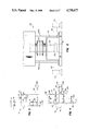
- FIG. 6 is a drawing in elevation showing the lower riser package and tieback tool of FIG. 5 in more detail.
- FIG. 7 is a schematic representation of the fluid flow path and major control valves for the lower riser package of FIG. 6.
- FIG. 8 is a drawing in elevation showing one embodiment of the present invention having a support vessel and flexible riser system with variable buoyancy for wireline servicing of a subsea well below the vessel.
- FIG. 9 is a drawing in elevation showing the flexibility of buoyancy cans attached to the lower portion of the flexible riser.
- FIG. 10 is a vertical section taken along line 10--10 of FIG. 9.
- FIG. 11 is a fragmentary section showing the attachment of a wire rope support to a buoyancy can.
- FIG. 12 is a detailed drawing showing the parts of a buoyancy can prior to attachment to the flexible riser.
- FIG. 13 is a schematic drawing in elevation showing a remotely operated vehicle (ROV) removing a tree cap from a subsea Christmas tree.
- ROV remotely operated vehicle
- FIG. 14 is a block diagram of the hydraulic control system and winches used to attach the flexible riser with its lower riser package to a subsea wellhead.
- FIG. 15 is a drawing in elevation with portions broken away showing modular equipment packages used to deploy and operate the flexible riser maintenance system.
- FIG. 16 is a plan view of the modular equipment packages shown in FIG. 15.
- subsea well 20 is shown having wellhead 30 and well bore 21 extending downwardly therefrom to one or more hydrocarbon producing formations (not shown).
- Tubing, casing, production packers, subsurface safety valves and other downhole equipment would be disposed within well bore 21 as required for specific well conditions.
- Production flow line 22 extends from wellhead 30 along the ocean floor 23 to a production facility (not shown). During normal operation, formation fluids flow into well bore 21 and are sent to the production facility via wellhead 30 and production flow line 22.
- Support vessel 60 on the ocean surface is shown with flexible riser means 40 extending therefrom.
- Flexible riser means 40 is attached to wellhead 30 to allow maintenance and servicing of wellbore 21 from support vessel 60.
- Flexible riser means 40 and support vessel 60 are arranged in FIG. 1 for wireline servicing.
- Flexible riser means 40 and support vessel 60 are arranged in FIG. 2 for through flow line (TFL) or pumpdown servicing. The difference between wireline and TFL servicing will be explained later.
- TFL flow line
- Support vessel 60 has several thrust motors and propellers 62 which maintain its position on the ocean surface relative to wellhead 30.
- Flexible riser means 40 can accommodate a substantial variation or offset between the actual position of vessel 60 and the point directly above wellhead 30. Also, well fluids are not produced through flexible riser means 40 since flow line 22 is available. Therefore, the present invention can be used on a much wider variety of support vessels and is not limited to support vessels having highly accurate, expensive position keeping or fluid handling capabilities.
- Support vessel 60 has a large opening or moonpool 61 extending from its main deck through its bottom.
- Moonpool 61 provides a protected area for handling and working with objects in the water below vessel 60.
- Conventional cranes 63 and 64 are provided on support vessel 60 to position flexible riser means 40 and other components of the maintenance system relative to moonpool 61.
- Powered reel 65 is provided on vessel 60 to pay out, take in and store flexible riser means 40.
- conventional wireline lubricator 66 is attached to the terminal end of flexible riser means 40 on vessel 60.
- Buoy 67 carried on the side of vessel 60, is attached by cable 68 near the upper end of flexible riser means 40.
- riser means 40 and buoy 67 could be released from support vessel 60.
- support vessel 60 can locate buoy 67 and reconnect to riser means 60. Alternative disconnect procedures will be described later.
- Subsea wellhead systems such as wellhead 30 have several distinct subsystems.
- the design of each wellhead and its subsystems varies between each major wellhead manufacturer.
- the principal subsystems include surface conductor pipe (not shown), suspension system (hangers) (not shown) for casing and tubing strings, guide base 50 and guide post 51, Christmas tree 31, and flow line connector 24.
- the present invention can be used with any subsea wellhead. The written specification will describe the present invention in relationship to a typical subsea wellhead 30 and subsea Christmas tree 31.
- FIG. 3 is a schematic drawing of the fluid flow path and major control valves typically associated with wellhead 30 for a single tubing string, wireline completion.
- Tubing string 25, disposed within well bore 21, would extend from wellhead 30 to a hydrocarbon producing formation (not shown).
- Subsurface safety valve 26 is generally installed in tubing string 25 below wellhead 30 to provide emergency shutoff of fluid flow in the event of damage to wellhead 30, Christmas tree 31, or flow lines 22.
- Christmas tree 31 is attached to wellhead 30 by tree connector 32.
- Tree 31 has two fluid flow passageways 33 and 34 extending longitudinally therethrough.
- Flow passageway 33 provides fluid communication and vertical access to tubing string 25.
- Flow passageway 34 provides fluid communication with the annulus between tubing 25 and well bore 21.
- Master valves 35 and 36 control fluid flow through passageways 33 and 34 respectively.
- Flow line connector 24 provides a means for releasably attaching flow lines 22a and 22b to Christmas tree 31.
- An example of a Christmas tree, tree cap and tree cap running tool is shown in U.S. Pat. No. 4,405,016.
- An example of a flow line connector is shown in U.S. Pat. No. 4,544,036.
- FIG. 4 is a schematic drawing of the fluid flow path and major control valves typically associated with wellhead 30a for a TFL type well completion.
- Tubing string 25, disposed within well bore 21, would extend from wellhead 30a to a hydrocarbon producing formation (not shown).
- second tubing string 25a is also disposed in well bore 21 to provide fluid communication from wellhead 30a to crossover 145.
- Second tubing string 25a and crossover 145 are used to provide a fluid flow path to pump TFL tool strings into and out of tubing string 25.
- Subsurface safety valves 26 are generally installed in tubing strings 25 and 25a for the same reasons as described for FIG. 3.
- Christmas trees 31a and 31 A major difference between Christmas trees 31a and 31 is the addition of TFL loops 143 and 144 which facilitate movement of TFL tools from flow lines 22a and 22b into longitudinal flow passageway 33a and 34a respectively. Another difference is that Christmas tree 31a has fluid flow passageways 33a, 34a, and 149 extending longitudinally therethrough. Flow passageways 33a, 34a, and 149 communicate with tubing strings 25, 25a and the annulus in well bore 21 respectively. Master valves 35, 36, and 146 and swab valves 37, 38, and 148 perform the same function as previously described for wellhead 30 (FIG. 3). Tree cap 39a can be removed to allow vertical access to flow passageways 33a, 34a and 149.
- FIG. 5 shows lower riser package 100 attached to tieback tool 101 by flanged connection 102.
- Lower riser package 100 functions as an interface between flexible riser means 40 and subsea tree 31 to provide both well control (subsurface safety valve 26) and tree control (valves 35, 36, 37, 38, etc.).
- Tieback tool 101 is preferably a tree running tool or wellhead connector means designed to releasably engage the specific Christmas tree used on wellhead 30. Using the appropriate tree running tool, available from the wellhead manufacturer, allows lower riser package 100 to service a wide variety of subsea wells.
- Flanged connection 102 can be readily adapted to accommodate any tree running tool as part of lower riser package 100.
- Tieback tool 101 has fluid flow passageways 103 extending longitudinally therethrough.
- Guide surface 104 and recess 105 are provided in passageway 103 to attach tieback tool 101 to a Christmas tree such as tree 31 or 31a.
- Guide surface 104 and recess 105 function as mating and sealing surfaces to releasably engage lower riser package 100 to wellhead 30 and to establish communication with wellhead 30 via Christmas tree 31.
- Guide arms 106 and funnels 107 may also be provided as part of tieback tool 101 to aid in aligning lower riser package 100 with the Christmas tree.
- the use of guide arm 106 and the design of funnel 107 is a function of the specific Christmas tree and wellhead design. Funnels 107 are designed for use with guide posts 51.
- a plurality of hydraulic/electric control lines 108 are attached to tieback tool 101 to allow control of master valves 35 and 36, swab valves 37 and 38 and the other components of tree 31. These control functions are part of the design of a tree running tool.
- One or more flow passageways 103 can be provided depending upon the Christmas tree design.
- FIG. 6 A more detailed drawing of lower riser package 100 is shown in FIG. 6.
- Adapter spool 109 is used to attach blowout preventer 110 and 111 to flanged connection 102.
- blowout preventer 110 would have shear rams and preventer 111 blind rams.
- Monitor valve 114 is provided to communicate with the annulus (not shown) between well bore 21 and tubing string 25.
- Flexible riser means 40 is attached to lower riser package 100 by connector 41.
- Frame 112 is secured to adapter spool 109 and surrounds blowout preventers 110 and 111 to provide support and protection.
- Buoyant material 113 can be attached to frame 112 as desired to adjust the buoyance of lower riser package 100.
- lower riser package 100 should preferably have slightly negative buoyancy to minimize the forces required to position lower riser package 100.
- Tag line winch 120 is also carried on lower riser package 100. Winch 120 is an important feature of the present invention to allow safe mating of lower riser package 100 with a Christmas tree.
- FIG. 7 is a schematic representation of the fluid flow path and major control valves for lower riser package 100a which is designed for use with Christmas tree 31a.
- Lower riser package 100a has three longitudinal flow passageways 115, 116, and 117 arranged to communicate with longitudinal flow passageways 33a, 34a, and 149, respectively, of tree 31a.
- Connector means or unions 118 and 119 are provided on lower riser package 100a to allow flexible riser means 40 to communicate with flow passageways 115 and 116.
- Tieback tool 101 assures proper mating and sealing with the respective flow passageways in tree 31a.
- Cross connect valve 306 may be hydraulically controlled for selected fluid communication between longitudinal flow passageways 115 and 116. Such fluid communication may be required for TFL work string movement or to flush riser means 40 for pollution control.
- Flexible riser means 40 preferably has variations in buoyancy along its length as shown in FIG. 8. Wireline servicing can best be performed in a vertical riser having no bends. However, maintaining a truly vertical riser over a fixed subsea wellhead requires expensive, sophisticated positioning equipment typically associated with a drilling vessel or semisubmersible. Varying the buoyancy of flexible riser means 40 results in a shallow S configuration which can accommodate a greater offset between support vessel 60 and the point directly above wellhead 30. The shallow S configuration which may cause some increased friction as the wireline rubs against the inside diameter of flexible riser means 40 still provides acceptable wireline characteristics. Also the shallow S configuration can accommodate movement of support vessel 60 from wave action without the need for attaching heavy motion compensators to flexible riser means 40 at the surface. Some motion compensation may be required while mating lower riser package 100 with tree 31.
- Flexible riser means 40 shown in FIG. 8 has a positive buoyancy portion 40a over approximately one-sixth of its length adjacent to lower riser package 100.
- a neutrally buoyant portion 40b has approximately the same length and is located adjacent to portion 40a.
- the remaining portion 40c would have standard (generally negative) buoyancy for the selected flexible riser.
- the ratio of 1/6:1/6:2/3 is preferred for wireline servicing of many existing subsea wells.
- One method to obtain the desired buoyancy characteristics for riser portion 40a is to attach a plurality of buoyancy cans 42 manufactured from a suitable material such as closed cell foam.
- Each buoyancy can 42 has two separate halves 42a and 42b which fit snugly around standard riser 40c.
- Banding straps 43 are secured around the two halves 42a and 42b.
- two or more wire cables 44 are attached to lower riser package 100 and the exterior of buoyancy cans 42.
- the upper end of each can 42 has a concave surface 45 to receive a matching convex surface 46 on the lower end of the adjacent can 42. Surfaces 45 and 46 cooperate to allow limited flexing of riser portion 40a without damaging buoyancy cans 42.
- Neutrally buoyant portion 40b may be formed in a manner similar to riser portion 40a by using smaller diameter cans 42.
- a buoyant sheath or covering 47 could be placed on the exterior of riser means 40 as shown in FIG. 15.
- Standard riser 40c is available from several manufacturers including Coflexip S.A., 23, avenue de Neuilly, 75116 Paris, France. Three inches would be a typical inside diameter for standard riser 40c.
- Modular equipment packages 70, 71, and 72 shown in FIGS. 15 and 16, can be easily transferred from one support vessel to another.
- Equipment packages 70, 71, and 72 include means for raising, lowering, and attaching flexible riser means 40 to wellhead 30.
- Modular equipment packages 70, 71 and 72 also include means for performing maintenance on subsea well 20 via flexible riser means 40.
- Equipment package 70 includes handling boom or davit 90 and enclosed control station 73.
- Equipment package 71 has first powered reel 75 to pay out, take up, and store flexible riser means 40 along with second powered reel 76 to pay out, take up, and store umbilical cable 77.
- Umbilical cable 77 provides electro/hydraulic power and monitoring/control lines to lower riser package 100.
- Enclosed control station 73 has the necessary panels, gauges, meters, monitoring equipment, etc., to allow operation of lower riser package 100, Christmas tree 31 and other components associated with wellhead 30 via umbilical cable 77.
- Package 72 includes second powered reel 78 with a second flexible riser means 40, TFL lubricators 79, TFL loading tray 80, and other TFL surface components 81-84.
- Handling boom 90 is used to move lower riser package 100 between its stored positions as shown in FIG. 15 and its launch position over the water (not shown).
- Winch 91 is attached to the top of boom 90 to lift lower riser package 100 by cables 92.
- Boom 90 is preferably a modified (parallel legs) davit. Each leg 93 of boom 90 is attached to equipment package 70 by pivot pins 94. Hydraulic cylinders and rams 95 are provided to rotate boom 90 between three positions--stored, lifting, and operating. In its operating position, boom 90 can launch and recover lower riser package 100.
- Fairlead tray 95 is carried by boom 90 to receive flexible riser means 40 therein. Fairlead tray 95 has a radius of curvature selected to accommodate riser means 40. A plurality of roller 96 are carried by fairlead tray 95 to allow flexible riser means 40 to freely move therethrough. Boom 90 includes level wind means 97 to reciprocate fairlead tray 95 between legs 93 as riser means 40 is paid out or taken up. Level wind means 97 prevents fouling of riser means 40 on powered reels 75 and 78.
- a system for servicing subsea well 20 via flexible riser means 40 must accomplish four functions: guidance during landing and release from wellhead 30, structural connection to subsea tree 31, vertical access to well bore 21, and control of both well bore 21 and tree 31.
- the operating procedures for servicing subsea well 20 can be divided into four stages: preparation, establishing the flexible riser maintenance system, normal operations, and emergency disconnect. Typical operating limits or criteria are attached as Exhibit A at the end of this written specification.
- This stage involves selecting a support vessel 60 with adequate position keeping capability and deck space for modular support equipment 70, 71, and 72 (if required).
- the desired length of flexible riser means 40 is spooled onto powered reel 75 (and 76 if required).
- the specific tree running tool and adapter which matches subsea tree 31 is attached to lower riser package 100 as tieback tool 101.
- An analysis of the docking steps and normal operation is conducted to determine the optimum configuration for flexible riser means 40 and the offset of vessel 60 from wellhead 30. Water depth and weather conditions are two of the most important variables that affect the preparation stage.
- ROV 160 remotely operated vehicle
- Various types of miniature, unmanned submarines are commercially available for use as ROV 160. Examples of some remotely operated vehicles are shown in U.S. Pat. No. 2,060,670 to H. Hartman; 3,626,703 to N. F. Richburg; and 4,034,568 to B. H. Mason.
- the use of ROV 160 also eliminates the need for guidelines between support vessel 60 and wellhead 30.
- FIG. 13 shows ROV 160 removing tree cap 39 from subsea tree 31.
- ROV 160 and its transport frame 161 would be a self-contained unit that could be lowered as a package by power cable 162 from support vessel 60.
- ROV 160 includes manipulator arm 163 and thrusters 164. Commands to and information from ROV 160 are communicated with support vessel 60 via power cable 162 and control cable 165. Thrusters 164 are used to move ROV 160 vertically and horizontally.
- ROV 160 is launched to attach an acoustic beacon (not shown) to wellhead 30.
- the beacon provides a fixed reference point for all further work.
- ROV 160 will next attach cable 166 from support vessel 60 to tree cap 39 and release tree cap 39 from subsea tree 31.
- ROV 160 cooperates with cable 166 to remove tree cap 39 without causing any damage to subsea tree 31.
- Lower riser package 100 is designed to remain in a vertical position throughout the docking step. This design is accomplished by varying the amount of buoyant material 113 such that lower riser package 200 has a negative buoyant force of at least 2000 pounds greater than the positive buoyant force of flexible riser means portion 40a attached thereto.
- FIG. 14 shows one system 170 to provide motion compensation for flexible riser means 40 during the docking phase.
- Winch 171 provides two inputs to electronic analog controller 175. They are water depth input 190 (length of line 172 paid out) and vertical velocity input 191 from shaft encoder 176 associated with winch 171. Normal operation of powered reel 75 is accomplished by manual operator 177 sending a signal to controller 175 which in turn positions hydraulic servo controls 178 as desired. Servo controls 178 direct power fluid to hydraulic motor 179 to rotate power reel 75 to either pay out or take up flexible riser means 40.
- lower riser package 100 includes tag line (constant tension) winch 120.
- ROV 160 can be used to attach tag line 121 to subsea tree 31 to measure the vertical distance (length of line 121 paid out) between lower riser package 100 and tree 31.
- This vertical distance is the third input 192 to electronic analog controller 175.
- controller 175 can automatically adjust the rate of descent of lower riser package 100 to a preselected value. This adjustment can be made as an override or modification of the signal from manual operator 177. An all electric system could be substituted for the electro/hydraulic system shown in FIG. 14.
- Flexible riser means 40 is structurally secured to wellhead 30 via lower riser package 100 and the releasable connection between tieback tool 101 and tree 31. Control of tree 31 and downhole safety valves 26 via umbilical cable 77 is transferred to vessel 60 after docking lower riser package 100.
- vessel 60 With lower riser package 100 releasably secured to tree 31, vessel 60 is positioned at the desired offset from wellhead 30.
- the terminal end of riser means 40 on vessel 60 is attached either to wireline lubricator 66 or TFL lubricators 79 by appropriate quick unions (not shown).
- the valves in tree 31 are opened and closed as required to perform the desired downhole maintenance via flexible riser means 40.
- Cross connect valve 306 may be opened to flush undesired well fluids out of flexible riser means 40.
- the tree valves are closed and lower riser package 100 released from tree 31.
- ROV 160 can assist with release as required by the specific tree design. Power reel 75 is used to retrieve flexible riser means 40 and lower riser package 100.
- Handling boom 90 is attached to lower riser package 100 when it nears the surface to lift lower riser package 100 out of the water and to return it in its stored position on modular equipment package 70.
- Tree cap 39 is installed on tree 31 by ROV 160 and the sonic beacon recovered.
- Well 20 is then ready to resume normal production via flow lines 22.
- Lower riser package 100 includes blowout preventers 110 and 111 which should be selected to shear off any tool used in the service tool string and form a fluid barrier in flow passageways 33 and 34. Blowout preventers 110 and 111 provide primary closure against well pressure during emergency disconnect. The valves in tree 31 and subsurface safety valve 26 may also close if they have not been disabled as part of the well servicing.
- a quick disconnect is located between lower riser package 100 and portion 40a of flexible riser means 40.
- Various types of quick disconnects are commercially available that will release flexible riser means 40 when a preselected amount of tension is applied.
- the upper end of flexible riser means 40 could be attached to buoy 67 and released from support vessel 60.
- Modular equipment package 70 and handling boom 90 can be positioned to allow deployment of flexible riser means 40 and lower riser package 100 from the stern or over the side of a support vessel.
- the present invention is not limited to only support vessels having moonpool 61 or a similar configuration.
- the present invention is not limited to servicing single, isolated subsea wells.
- flexible riser means 40 and lower riser package 100 can be used to service a subsea well which is part of a "subsea template" or group of subsea wells.
- the principal requirement is that sufficient room (offset) be available to accommodate support vessel 60 relative to the subsea wellhead that will receive lower riser package 100.
- Production flow line 22 could extend upwardly to any type of production facility (not shown) as long as neither flow line 22 nor the production facility blocked access to the subsea wellhead by lower riser package 100.
- the present invention could be used on injection wells that maintain formation pressure and is not limited to only producing wells.
- Umbilical cable 77 could be used to provide power and control for the ROV portion of the modified lower riser package (not shown).
- the modified lower riser package would include thrusters, power pack, position sensors, and control system similar to ROV 160.
- Lower riser package 100 could also contain one or more thrusters to provide additional vertical thrust to assist ROV 160 in landing lower riser package 100 on tree 31.
Abstract
Description
                                  EXHIBIT A
__________________________________________________________________________
FLEXIBLE RISER OPERATIONAL LIMITS AND CRITERIA
ALLOWABLE LIMIT    WIRELINE                PUMPDOWN
__________________________________________________________________________
RADIUS OF CURVATURE FOR
                   FOR 3" ID TOOLS
TOOL PASSAGE
RISER ID           UNMODIFIED TOOLS
                                MODIFIED TOOLS
3"                 64'          20'        5'
4"                 20'           5'        5' (Must have
                                           parking tool.
HORIZONTAL MID-SPAN ANGLE
POSSIBLE LOW POINT 30°-45°
WIRE/RISER FRICTION
                   20°-30°   NOT APPLICABLE
LOADS
ON TREE
                    ##STR1##
                                            ##STR2##
ON RISER TENSION   150 KIPS(3" ID -        150 KIPS(3" ID -
                   5000 psi)               5000 psi)
BENDING            MIN. 2.6 FT. (3" ID)    MIN. 2.6 FT. (3" ID)
                   MIN. 3.8 FT. (4" ID)    MIN. 3.8 FT.
__________________________________________________________________________
                                           (4" ID)
Claims (28)
Priority Applications (7)
| Application Number | Priority Date | Filing Date | Title |
|---|---|---|---|
| US06/944,874 US4730677A (en) | 1986-12-22 | 1986-12-22 | Method and system for maintenance and servicing of subsea wells |
| GB8719701A GB2199056B (en) | 1986-12-22 | 1987-08-20 | Method and system for maintenance and servicing of subsea wells |
| CA000550117A CA1285472C (en) | 1986-12-22 | 1987-10-23 | Method and system for maintenance and servicing of subsea wells |
| BR8706022A BR8706022A (en) | 1986-12-22 | 1987-11-05 | SYSTEM TO PROVIDE TECHNICAL ASSISTANCE TO SUBMARINE POCOS, FLEXIBLE VERTICAL TUBE, FLEXIBLE VERTICAL TUBE AND LOWER VERTICAL TUBE AND METHOD TO PROVIDE TECHNICAL ASSISTANCE TO SUBMARINE POCOS |
| NO875250A NO875250L (en) | 1986-12-22 | 1987-12-16 | PROCEDURE AND DEVICE FOR MAINTENANCE AND OPERATION OF UNDERGROUND BURNER. |
| GB9021300A GB2234771B (en) | 1986-12-22 | 1990-10-01 | Risers for subsea well servicing |
| GB9021301A GB2234772B (en) | 1986-12-22 | 1990-10-01 | Risers for subsea well servicing |
Applications Claiming Priority (1)
| Application Number | Priority Date | Filing Date | Title |
|---|---|---|---|
| US06/944,874 US4730677A (en) | 1986-12-22 | 1986-12-22 | Method and system for maintenance and servicing of subsea wells |
Publications (1)
| Publication Number | Publication Date |
|---|---|
| US4730677A true US4730677A (en) | 1988-03-15 |
Family
ID=25482207
Family Applications (1)
| Application Number | Title | Priority Date | Filing Date |
|---|---|---|---|
| US06/944,874 Expired - Fee Related US4730677A (en) | 1986-12-22 | 1986-12-22 | Method and system for maintenance and servicing of subsea wells |
Country Status (5)
| Country | Link |
|---|---|
| US (1) | US4730677A (en) |
| BR (1) | BR8706022A (en) |
| CA (1) | CA1285472C (en) |
| GB (3) | GB2199056B (en) |
| NO (1) | NO875250L (en) |
Cited By (80)
| Publication number | Priority date | Publication date | Assignee | Title |
|---|---|---|---|---|
| US4906137A (en) * | 1988-02-24 | 1990-03-06 | Coflexip | Apparatus for transferring fluid between subsea floor and the surface |
| US4934871A (en) * | 1988-12-19 | 1990-06-19 | Atlantic Richfield Company | Offshore well support system |
| US5547314A (en) * | 1995-06-08 | 1996-08-20 | Marathon Oil Company | Offshore system and method for storing and tripping a continuous length of jointed tubular conduit |
| WO1997030265A1 (en) * | 1996-02-14 | 1997-08-21 | Kværner Oilfield Products A.S | Offshore production piping and method for laying same |
| WO1997047851A1 (en) * | 1996-06-12 | 1997-12-18 | Oceaneering International, Inc. | Subsea connection |
| WO1999050526A1 (en) | 1998-03-30 | 1999-10-07 | Kellogg Brown & Root, Inc. | Extended reach tie-back system |
| EP0952300A1 (en) * | 1998-03-27 | 1999-10-27 | Cooper Cameron Corporation | Method and apparatus for drilling a plurality of offshore underwater wells |
| US5992526A (en) * | 1997-12-03 | 1999-11-30 | Fmc Corporation | ROV deployed tree cap for a subsea tree and method of installation |
| US6068427A (en) * | 1995-12-22 | 2000-05-30 | Abb Offshore Technology As | System and method for replacement of components on sea bottom-based installations |
| WO2000043632A2 (en) | 1999-01-19 | 2000-07-27 | Colin Stuart Headworth | System with a compliant guide and method for inserting a coiled tubing into an oil well |
| US6161619A (en) * | 1998-02-06 | 2000-12-19 | Head; Philip | Riser system for sub-sea wells and method of operation |
| US6216789B1 (en) | 1999-07-19 | 2001-04-17 | Schlumberger Technology Corporation | Heave compensated wireline logging winch system and method of use |
| EP1092078A1 (en) * | 1998-07-02 | 2001-04-18 | Fmc Corporation | Flying lead workover interface system |
| EP1097287A1 (en) * | 1998-07-10 | 2001-05-09 | Fmc Corporation | Floating spar for supporting production risers |
| US6276456B1 (en) * | 1998-02-06 | 2001-08-21 | Philip Head | Riser system for sub-sea wells and method of operation |
| WO2001061145A1 (en) * | 2000-02-21 | 2001-08-23 | Fmc Kongsberg Subsea As | Intervention device for a subsea well, and method and cable for use with the device |
| WO2002088517A1 (en) * | 2001-05-02 | 2002-11-07 | Shell Internationale Research Maatschappij B.V. | System for retrieving a tubular element from a well |
| US6591913B2 (en) * | 2001-12-12 | 2003-07-15 | Oceaneering International, Inc. | System and method for lessening impact on Christmas trees during downhole operations involving Christmas trees |
| US6601656B2 (en) * | 1998-03-27 | 2003-08-05 | Cooper Cameron Corporation | Method and apparatus for drilling an offshore underwater well |
| US6612369B1 (en) * | 2001-06-29 | 2003-09-02 | Kvaerner Oilfield Products | Umbilical termination assembly and launching system |
| US20040016548A1 (en) * | 2002-07-29 | 2004-01-29 | Barratt Richard Kenneth Oakley | Steel tube flying lead jumper connector |
| US20040026081A1 (en) * | 2002-08-07 | 2004-02-12 | Horton Edward E. | System for accommodating motion of a floating body |
| US6698722B1 (en) * | 1999-03-22 | 2004-03-02 | Deep Tek Limited | Apparatus and method for use in handling a load |
| US20040127084A1 (en) * | 2001-05-17 | 2004-07-01 | Allan Glennie | Connector |
| US6782950B2 (en) | 2000-09-29 | 2004-08-31 | Kellogg Brown & Root, Inc. | Control wellhead buoy |
| WO2004079149A2 (en) * | 2003-03-05 | 2004-09-16 | Torres Carlos A | Subsea well workover system and method |
| US20040188094A1 (en) * | 2003-03-24 | 2004-09-30 | Michael Piecyk | Wireline subsea metering head and method of use |
| US20050006101A1 (en) * | 2003-06-02 | 2005-01-13 | Aker Riser Systems As | Riser |
| US6868902B1 (en) | 2002-01-14 | 2005-03-22 | Itrec B.V. | Multipurpose reeled tubing assembly |
| US20060005971A1 (en) * | 2004-07-12 | 2006-01-12 | Deep Down Inc. | Method and apparatus for installing an undersea umbilical |
| US20060017287A1 (en) * | 2002-09-09 | 2006-01-26 | Dril-Quip, Inc. | Tie-back connection for subsea well |
| US20060021756A1 (en) * | 2004-08-02 | 2006-02-02 | Kellogg Brown And Root, Inc. | Dry tree subsea well communications apparatus and method using variable tension large offset risers |
| US20060090898A1 (en) * | 2004-10-19 | 2006-05-04 | Oceaneering International, Inc. | Subsea junction plate assembly running tool and method of installation |
| US20060161089A1 (en) * | 2004-12-30 | 2006-07-20 | Bayer Innovation Gmbh | Compositions and processes for accelerated wound healing using novel fibrous webbings |
| US20060180313A1 (en) * | 2005-02-11 | 2006-08-17 | Oceaneering International, Inc. | Subsea hydraulic junction plate actuator with R.O.V. mechanical override |
| US20060219412A1 (en) * | 2005-04-05 | 2006-10-05 | Yater Ronald W | Subsea intervention fluid transfer system |
| US20060231264A1 (en) * | 2005-03-11 | 2006-10-19 | Boyce Charles B | Riserless modular subsea well intervention, method and apparatus |
| US20060231263A1 (en) * | 2005-03-11 | 2006-10-19 | Sonsub Inc. | Riserless modular subsea well intervention, method and apparatus |
| US20070048093A1 (en) * | 2005-08-30 | 2007-03-01 | Kellogg Brown And Root, Inc. | Subsea well communications apparatus and method using variable tension large offset risers |
| US20070163481A1 (en) * | 2006-01-19 | 2007-07-19 | Stein Vedeld | Submerged loading system |
| US20080014026A1 (en) * | 2003-09-09 | 2008-01-17 | Sylvain Routeau | Method for installing and connecting a sub-sea riser |
| US20080017385A1 (en) * | 2001-09-15 | 2008-01-24 | Robert Gibson | Buoyancy element and module |
| WO2008118680A1 (en) * | 2007-03-26 | 2008-10-02 | Schlumberger Canada Limited | System and method for performing intervention operations with a compliant guide |
| WO2008155046A1 (en) * | 2007-06-19 | 2008-12-24 | Services Petroliers Schlumberger | Apparatus for subsea intervention |
| WO2009012349A1 (en) * | 2007-07-17 | 2009-01-22 | Oceaneering International, Inc. | Subsea structure load monitoring and control system |
| US20090038804A1 (en) * | 2007-08-09 | 2009-02-12 | Going Iii Walter S | Subsurface Safety Valve for Electric Subsea Tree |
| US20090129867A1 (en) * | 2007-11-20 | 2009-05-21 | Millheim Keith K | Self-Standing Riser and Buoyancy Device Deployment and Positioning System |
| US20090178848A1 (en) * | 2008-01-10 | 2009-07-16 | Perry Slingsby Systems, Inc. | Subsea Drilling System and Method for Operating the Drilling System |
| US20090191001A1 (en) * | 2008-01-25 | 2009-07-30 | Colin Headworth | Connecting compliant tubular members at subsea locations |
| US20090212969A1 (en) * | 2008-02-26 | 2009-08-27 | Vecto Gray Inc. | Underwater Communications Using RF |
| US20090232664A1 (en) * | 2008-03-12 | 2009-09-17 | General Electric | Permanent magnet motor for subsea pump drive |
| US20090260830A1 (en) * | 2008-04-18 | 2009-10-22 | Henning Hansen | Rigless well completion method |
| US20100000739A1 (en) * | 2008-07-02 | 2010-01-07 | Cuiper Glen H | Variable buoyancy subsea running tool |
| US20100038091A1 (en) * | 2008-08-14 | 2010-02-18 | Daniel Sack | System and method for deployment of a subsea well intervention system |
| WO2010020353A1 (en) * | 2008-08-20 | 2010-02-25 | Services Petroliers Schlumberger | System and method for connecting and aligning a compliant guide |
| WO2010032019A1 (en) * | 2008-09-16 | 2010-03-25 | Enovate Systems Limited | Subsea apparatus |
| WO2010042873A2 (en) * | 2008-10-10 | 2010-04-15 | Cameron International Corporation | Integrated installation and workover controll system |
| WO2010066874A2 (en) * | 2008-12-12 | 2010-06-17 | Welltec A/S | Subsea well intervention module |
| US20100147529A1 (en) * | 2005-08-30 | 2010-06-17 | Kellogg Brown & Root Llc | Systems and Methods for Controlling Risers |
| US20100300697A1 (en) * | 2007-10-10 | 2010-12-02 | Itrec B.V | Installing an expandable tubular in a subsea wellbore |
| US20100314132A1 (en) * | 2009-06-11 | 2010-12-16 | Coles Robert A | Method and apparatus for performing continuous tubing operations |
| US20110067881A1 (en) * | 2008-12-16 | 2011-03-24 | Chevron U.S.A. Inc. | System and method for delivering material to a subsea well |
| US7958938B2 (en) | 2004-05-03 | 2011-06-14 | Exxonmobil Upstream Research Company | System and vessel for supporting offshore fields |
| US20110142543A1 (en) * | 2009-12-14 | 2011-06-16 | Subsea 7 Limited | Method of Using Sacrificial Pipe String |
| WO2011128355A3 (en) * | 2010-04-14 | 2012-02-16 | Aker Subsea As | System for installing and testing subsea wellhead equipment |
| US20120103622A1 (en) * | 2010-11-01 | 2012-05-03 | Vetco Gray Inc. | Efficient open water riser deployment |
| US8214993B1 (en) | 2009-11-11 | 2012-07-10 | Coastal Cargo Company, Inc. | Method and apparatus for removing or reinstalling riser pipes of a riser bundle |
| CN102822443A (en) * | 2010-03-15 | 2012-12-12 | 韦尔泰克有限公司 | Subsea well intervention module |
| US20140079512A1 (en) * | 2011-05-06 | 2014-03-20 | National Oilwell Varco Denmark I/S | Offshore system |
| US9605772B2 (en) * | 2012-05-15 | 2017-03-28 | Schlumberger Technology Corporation | Quick disconnect system |
| US9719330B2 (en) * | 2015-12-28 | 2017-08-01 | Cameron International Corporation | Subsea equipment pendulum arrestor and method for its use |
| CN107218016A (en) * | 2017-07-13 | 2017-09-29 | 安世亚太科技股份有限公司 | Connecting connection parts under deep sea vertical pipe |
| WO2017205757A1 (en) * | 2016-05-27 | 2017-11-30 | Oceaneering International, Inc. | Connector maintenance panel |
| US10160528B2 (en) * | 2014-09-19 | 2018-12-25 | Aker Solutions As | Handling device for an installable and retrievable subsea apparatus |
| WO2019043385A1 (en) * | 2017-08-30 | 2019-03-07 | Subsea 7 Limited | Controlling subsea apparatus |
| US10364609B2 (en) | 2015-09-15 | 2019-07-30 | Noble Drilling Services Inc. | Method for excavating mud line cellar for subsea well drilling |
| US11268354B2 (en) * | 2020-06-18 | 2022-03-08 | Trendsetter Engineering, Inc. | Method and apparatus for temporary injection using a dynamically positioned vessel |
| CN115298411A (en) * | 2019-12-05 | 2022-11-04 | 巴西石油公司 | Method for cleaning up coiled tubing from a well intervention rig using coiled tubing |
| US11512550B2 (en) * | 2019-11-22 | 2022-11-29 | Conocophillips Company | Delivering fluid to a subsea wellhead |
| CN115298411B (en) * | 2019-12-05 | 2024-05-03 | 巴西石油公司 | Method for cleaning flexible tubing from a well intervention rig using a flexible tubing |
Families Citing this family (11)
| Publication number | Priority date | Publication date | Assignee | Title |
|---|---|---|---|---|
| GB9501642D0 (en) * | 1995-01-27 | 1995-03-15 | Head Philip | Well intervention apparatus |
| GB9715537D0 (en) * | 1997-07-24 | 1997-10-01 | Coflexip Stena Offshore Ltd | Marine riser and method of use |
| NO996163L (en) * | 1998-12-14 | 2000-06-15 | Vetco Gray Inc Abb | Self-supporting, disconnected riser system |
| US6826484B2 (en) | 2001-07-31 | 2004-11-30 | Pgs Americas, Inc. | 3D prestack time migration method |
| US8413723B2 (en) | 2006-01-12 | 2013-04-09 | Schlumberger Technology Corporation | Methods of using enhanced wellbore electrical cables |
| US7845412B2 (en) | 2007-02-06 | 2010-12-07 | Schlumberger Technology Corporation | Pressure control with compliant guide |
| US20080185153A1 (en) * | 2007-02-07 | 2008-08-07 | Schlumberger Technology Corporation | Subsea intervention with compliant guide |
| US9412492B2 (en) | 2009-04-17 | 2016-08-09 | Schlumberger Technology Corporation | Torque-balanced, gas-sealed wireline cables |
| US11387014B2 (en) | 2009-04-17 | 2022-07-12 | Schlumberger Technology Corporation | Torque-balanced, gas-sealed wireline cables |
| CA2774775A1 (en) | 2009-09-22 | 2011-03-31 | Schlumberger Canada Limited | Wireline cable for use with downhole tractor assemblies |
| US9752391B2 (en) | 2014-08-12 | 2017-09-05 | Onesubsea Ip Uk Limited | Variable guide and protection bushing for well conveyance |
Citations (11)
| Publication number | Priority date | Publication date | Assignee | Title |
|---|---|---|---|---|
| US2060670A (en) * | 1931-11-13 | 1936-11-10 | Hartman Hans | Submarine television |
| US3626703A (en) * | 1969-11-18 | 1971-12-14 | Twanoh Marine Charters Inc | Underwater exploration and recovery vehicle |
| US4034568A (en) * | 1975-12-12 | 1977-07-12 | Burton Hoster Mason | Underwater clamping mechanism |
| US4176986A (en) * | 1977-11-03 | 1979-12-04 | Exxon Production Research Company | Subsea riser and flotation means therefor |
| US4281716A (en) * | 1979-08-13 | 1981-08-04 | Standard Oil Company (Indiana) | Flexible workover riser system |
| US4405016A (en) * | 1980-12-18 | 1983-09-20 | Smith International, Inc. | Underwater Christmas tree cap and lockdown apparatus |
| US4423983A (en) * | 1981-08-14 | 1984-01-03 | Sedco-Hamilton Production Services | Marine riser system |
| US4470722A (en) * | 1981-12-31 | 1984-09-11 | Exxon Production Research Co. | Marine production riser system and method of installing same |
| US4544036A (en) * | 1984-02-17 | 1985-10-01 | Mobil Oil Corporation | Vertical flowline connector |
| US4556340A (en) * | 1983-08-15 | 1985-12-03 | Conoco Inc. | Method and apparatus for production of subsea hydrocarbons using a floating vessel |
| US4570716A (en) * | 1982-12-28 | 1986-02-18 | Coflexip | System and apparatus of liason between an underwater wellhead and a surface support |
-
1986
- 1986-12-22 US US06/944,874 patent/US4730677A/en not_active Expired - Fee Related
-
1987
- 1987-08-20 GB GB8719701A patent/GB2199056B/en not_active Expired - Fee Related
- 1987-10-23 CA CA000550117A patent/CA1285472C/en not_active Expired - Fee Related
- 1987-11-05 BR BR8706022A patent/BR8706022A/en not_active IP Right Cessation
- 1987-12-16 NO NO875250A patent/NO875250L/en unknown
-
1990
- 1990-10-01 GB GB9021300A patent/GB2234771B/en not_active Expired - Fee Related
- 1990-10-01 GB GB9021301A patent/GB2234772B/en not_active Expired - Fee Related
Patent Citations (11)
| Publication number | Priority date | Publication date | Assignee | Title |
|---|---|---|---|---|
| US2060670A (en) * | 1931-11-13 | 1936-11-10 | Hartman Hans | Submarine television |
| US3626703A (en) * | 1969-11-18 | 1971-12-14 | Twanoh Marine Charters Inc | Underwater exploration and recovery vehicle |
| US4034568A (en) * | 1975-12-12 | 1977-07-12 | Burton Hoster Mason | Underwater clamping mechanism |
| US4176986A (en) * | 1977-11-03 | 1979-12-04 | Exxon Production Research Company | Subsea riser and flotation means therefor |
| US4281716A (en) * | 1979-08-13 | 1981-08-04 | Standard Oil Company (Indiana) | Flexible workover riser system |
| US4405016A (en) * | 1980-12-18 | 1983-09-20 | Smith International, Inc. | Underwater Christmas tree cap and lockdown apparatus |
| US4423983A (en) * | 1981-08-14 | 1984-01-03 | Sedco-Hamilton Production Services | Marine riser system |
| US4470722A (en) * | 1981-12-31 | 1984-09-11 | Exxon Production Research Co. | Marine production riser system and method of installing same |
| US4570716A (en) * | 1982-12-28 | 1986-02-18 | Coflexip | System and apparatus of liason between an underwater wellhead and a surface support |
| US4556340A (en) * | 1983-08-15 | 1985-12-03 | Conoco Inc. | Method and apparatus for production of subsea hydrocarbons using a floating vessel |
| US4544036A (en) * | 1984-02-17 | 1985-10-01 | Mobil Oil Corporation | Vertical flowline connector |
Cited By (170)
| Publication number | Priority date | Publication date | Assignee | Title |
|---|---|---|---|---|
| US4906137A (en) * | 1988-02-24 | 1990-03-06 | Coflexip | Apparatus for transferring fluid between subsea floor and the surface |
| US4934871A (en) * | 1988-12-19 | 1990-06-19 | Atlantic Richfield Company | Offshore well support system |
| US5547314A (en) * | 1995-06-08 | 1996-08-20 | Marathon Oil Company | Offshore system and method for storing and tripping a continuous length of jointed tubular conduit |
| US6068427A (en) * | 1995-12-22 | 2000-05-30 | Abb Offshore Technology As | System and method for replacement of components on sea bottom-based installations |
| WO1997030265A1 (en) * | 1996-02-14 | 1997-08-21 | Kværner Oilfield Products A.S | Offshore production piping and method for laying same |
| US5794701A (en) * | 1996-06-12 | 1998-08-18 | Oceaneering International, Inc. | Subsea connection |
| GB2330603B (en) * | 1996-06-12 | 2000-09-06 | Oceaneering Int Inc | Subsea Connection |
| GB2330603A (en) * | 1996-06-12 | 1999-04-28 | Oceaneering Int Inc | Subsea Connection |
| WO1997047851A1 (en) * | 1996-06-12 | 1997-12-18 | Oceaneering International, Inc. | Subsea connection |
| US5992526A (en) * | 1997-12-03 | 1999-11-30 | Fmc Corporation | ROV deployed tree cap for a subsea tree and method of installation |
| US6276456B1 (en) * | 1998-02-06 | 2001-08-21 | Philip Head | Riser system for sub-sea wells and method of operation |
| US6161619A (en) * | 1998-02-06 | 2000-12-19 | Head; Philip | Riser system for sub-sea wells and method of operation |
| US6725936B2 (en) | 1998-03-27 | 2004-04-27 | Cooper Cameron Corporation | Method for drilling a plurality of offshore underwater wells |
| US6497286B1 (en) | 1998-03-27 | 2002-12-24 | Cooper Cameron Corporation | Method and apparatus for drilling a plurality of offshore underwater wells |
| EP0952300A1 (en) * | 1998-03-27 | 1999-10-27 | Cooper Cameron Corporation | Method and apparatus for drilling a plurality of offshore underwater wells |
| US6601656B2 (en) * | 1998-03-27 | 2003-08-05 | Cooper Cameron Corporation | Method and apparatus for drilling an offshore underwater well |
| US6752214B2 (en) | 1998-03-30 | 2004-06-22 | Kellogg Brown & Root, Inc. | Extended reach tie-back system |
| EP1075584A1 (en) * | 1998-03-30 | 2001-02-14 | Kellogg Brown & Root, Inc. | Extended reach tie-back system |
| EP1075584A4 (en) * | 1998-03-30 | 2005-02-09 | Kellogg Brown & Root Inc | Extended reach tie-back system |
| US6536528B1 (en) | 1998-03-30 | 2003-03-25 | Kellogg Brown & Root, Inc. | Extended reach tie-back system |
| WO1999050526A1 (en) | 1998-03-30 | 1999-10-07 | Kellogg Brown & Root, Inc. | Extended reach tie-back system |
| EP1092078A1 (en) * | 1998-07-02 | 2001-04-18 | Fmc Corporation | Flying lead workover interface system |
| EP1092078A4 (en) * | 1998-07-02 | 2002-07-24 | Fmc Corp | Flying lead workover interface system |
| EP1097287A4 (en) * | 1998-07-10 | 2002-03-27 | Fmc Corp | Floating spar for supporting production risers |
| US6336421B1 (en) * | 1998-07-10 | 2002-01-08 | Fmc Corporation | Floating spar for supporting production risers |
| EP1097287A1 (en) * | 1998-07-10 | 2001-05-09 | Fmc Corporation | Floating spar for supporting production risers |
| US6745840B2 (en) | 1999-01-19 | 2004-06-08 | Colin Stuart Headworth | System for accessing oil wells with compliant guide and coiled tubing |
| WO2000043632A3 (en) * | 1999-01-19 | 2001-01-04 | Colin Stuart Headworth | System with a compliant guide and method for inserting a coiled tubing into an oil well |
| GB2362409A (en) * | 1999-01-19 | 2001-11-21 | Colin Stuart Headworth | A system for accessing oil wells with compliant guide and coiled tubing |
| US6834724B2 (en) | 1999-01-19 | 2004-12-28 | Colin Stuart Headworth | System for accessing oil wells with compliant guide and coiled tubing |
| US6386290B1 (en) | 1999-01-19 | 2002-05-14 | Colin Stuart Headworth | System for accessing oil wells with compliant guide and coiled tubing |
| WO2000043632A2 (en) | 1999-01-19 | 2000-07-27 | Colin Stuart Headworth | System with a compliant guide and method for inserting a coiled tubing into an oil well |
| GB2362409B (en) * | 1999-01-19 | 2003-09-24 | Colin Stuart Headworth | A system for accessing oil wells with spoolable compliant guide and coiled tubing |
| US6691775B2 (en) | 1999-01-19 | 2004-02-17 | Colin Stuart Headworth | System for accessing oil wells with compliant guide and coiled tubing |
| NO338031B1 (en) * | 1999-01-19 | 2016-07-25 | Schlumberger Technology Corp | System for access to oil wells with resilient conductor and coiled tubing |
| US6698722B1 (en) * | 1999-03-22 | 2004-03-02 | Deep Tek Limited | Apparatus and method for use in handling a load |
| US6216789B1 (en) | 1999-07-19 | 2001-04-17 | Schlumberger Technology Corporation | Heave compensated wireline logging winch system and method of use |
| WO2001061145A1 (en) * | 2000-02-21 | 2001-08-23 | Fmc Kongsberg Subsea As | Intervention device for a subsea well, and method and cable for use with the device |
| US20030155127A1 (en) * | 2000-02-21 | 2003-08-21 | Hans-Paul Carlsen | Intervention device for a subsea well, and method and cable for use with the device |
| US6782950B2 (en) | 2000-09-29 | 2004-08-31 | Kellogg Brown & Root, Inc. | Control wellhead buoy |
| US7314088B2 (en) | 2001-05-02 | 2008-01-01 | Shell Oil Company | System for retrieving a tubular element from a well |
| GB2392693A (en) * | 2001-05-02 | 2004-03-10 | Shell Int Research | System for retrieving a tubular element from a well |
| WO2002088517A1 (en) * | 2001-05-02 | 2002-11-07 | Shell Internationale Research Maatschappij B.V. | System for retrieving a tubular element from a well |
| US20040194962A1 (en) * | 2001-05-02 | 2004-10-07 | Betts Michael John | System for retrieving a tubular element from a well |
| US20040127084A1 (en) * | 2001-05-17 | 2004-07-01 | Allan Glennie | Connector |
| EP1412611A2 (en) * | 2001-06-29 | 2004-04-28 | Kvaerner Oilfield Products, Inc. | Umbilical termination assembly and launching system related application information |
| WO2003002407A3 (en) * | 2001-06-29 | 2003-12-18 | Kvaerner Oildfield Products In | Umbilical termination assembly and launching system |
| US6612369B1 (en) * | 2001-06-29 | 2003-09-02 | Kvaerner Oilfield Products | Umbilical termination assembly and launching system |
| EP1412611A4 (en) * | 2001-06-29 | 2011-03-30 | Aker Subsea Inc | Umbilical termination assembly and launching system related application information |
| US20080017385A1 (en) * | 2001-09-15 | 2008-01-24 | Robert Gibson | Buoyancy element and module |
| EP1463870A2 (en) * | 2001-12-12 | 2004-10-06 | Oceaneering International, Inc. | System and method for lessening impact on christmas trees during downhole operations involving christmas trees |
| US6591913B2 (en) * | 2001-12-12 | 2003-07-15 | Oceaneering International, Inc. | System and method for lessening impact on Christmas trees during downhole operations involving Christmas trees |
| EP1463870A4 (en) * | 2001-12-12 | 2006-03-08 | Oceaneering Int Inc | System and method for lessening impact on christmas trees during downhole operations involving christmas trees |
| US6868902B1 (en) | 2002-01-14 | 2005-03-22 | Itrec B.V. | Multipurpose reeled tubing assembly |
| US6880640B2 (en) * | 2002-07-29 | 2005-04-19 | Offshore Systems Inc. | Steel tube flying lead jumper connector |
| US20040016548A1 (en) * | 2002-07-29 | 2004-01-29 | Barratt Richard Kenneth Oakley | Steel tube flying lead jumper connector |
| US20040026081A1 (en) * | 2002-08-07 | 2004-02-12 | Horton Edward E. | System for accommodating motion of a floating body |
| US20060017287A1 (en) * | 2002-09-09 | 2006-01-26 | Dril-Quip, Inc. | Tie-back connection for subsea well |
| WO2004079149A2 (en) * | 2003-03-05 | 2004-09-16 | Torres Carlos A | Subsea well workover system and method |
| WO2004079149A3 (en) * | 2003-03-05 | 2004-12-29 | Carlos A Torres | Subsea well workover system and method |
| US20040194963A1 (en) * | 2003-03-05 | 2004-10-07 | Torres Carlos A. | Subsea well workover system and method |
| US7000903B2 (en) * | 2003-03-24 | 2006-02-21 | Oceaneering International, Inc. | Wireline subsea metering head and method of use |
| US20040188094A1 (en) * | 2003-03-24 | 2004-09-30 | Michael Piecyk | Wireline subsea metering head and method of use |
| US20050006101A1 (en) * | 2003-06-02 | 2005-01-13 | Aker Riser Systems As | Riser |
| US7163062B2 (en) * | 2003-06-02 | 2007-01-16 | Aker Riser Systems As | Riser |
| US7600569B2 (en) * | 2003-09-09 | 2009-10-13 | Technip France | Method for installing and connecting a sub-sea riser |
| US20080014026A1 (en) * | 2003-09-09 | 2008-01-17 | Sylvain Routeau | Method for installing and connecting a sub-sea riser |
| US7958938B2 (en) | 2004-05-03 | 2011-06-14 | Exxonmobil Upstream Research Company | System and vessel for supporting offshore fields |
| US20060005971A1 (en) * | 2004-07-12 | 2006-01-12 | Deep Down Inc. | Method and apparatus for installing an undersea umbilical |
| US7467662B2 (en) * | 2004-07-12 | 2008-12-23 | Deep Down, Inc. | Method and apparatus for installing an undersea umbilical |
| US20070107906A1 (en) * | 2004-08-02 | 2007-05-17 | Bhat Shankar U | Dry tree subsea well communications apparatus using variable tension large offset risers |
| US20070107905A1 (en) * | 2004-08-02 | 2007-05-17 | Bhat Shankar U | Dry tree subsea well communications methods using variable tension large offset risers |
| US7628206B2 (en) * | 2004-08-02 | 2009-12-08 | Kellogg Brown & Root Llc | Dry tree subsea well communications apparatus using variable tension large offset risers |
| US20060021756A1 (en) * | 2004-08-02 | 2006-02-02 | Kellogg Brown And Root, Inc. | Dry tree subsea well communications apparatus and method using variable tension large offset risers |
| US7191836B2 (en) * | 2004-08-02 | 2007-03-20 | Kellogg Brown & Root Llc | Dry tree subsea well communications apparatus and method using variable tension large offset risers |
| US7520331B2 (en) | 2004-08-02 | 2009-04-21 | Kellogg Brown & Root Llc | Dry tree subsea well communications methods using variable tension large offset risers |
| US7243729B2 (en) | 2004-10-19 | 2007-07-17 | Oceaneering International, Inc. | Subsea junction plate assembly running tool and method of installation |
| US20060090898A1 (en) * | 2004-10-19 | 2006-05-04 | Oceaneering International, Inc. | Subsea junction plate assembly running tool and method of installation |
| US20060161089A1 (en) * | 2004-12-30 | 2006-07-20 | Bayer Innovation Gmbh | Compositions and processes for accelerated wound healing using novel fibrous webbings |
| US8088965B2 (en) | 2004-12-30 | 2012-01-03 | Bayer Innovation Gmbh | Method for accelerated wound healing using novel fibrous webbings |
| US7311035B2 (en) | 2005-02-11 | 2007-12-25 | Oceaneering International, Inc. | Subsea hydraulic junction plate actuator with R.O.V. mechanical override |
| US20060180313A1 (en) * | 2005-02-11 | 2006-08-17 | Oceaneering International, Inc. | Subsea hydraulic junction plate actuator with R.O.V. mechanical override |
| US7487836B2 (en) * | 2005-03-11 | 2009-02-10 | Saipem America Inc. | Riserless modular subsea well intervention, method and apparatus |
| US7891429B2 (en) * | 2005-03-11 | 2011-02-22 | Saipem America Inc. | Riserless modular subsea well intervention, method and apparatus |
| US20060231263A1 (en) * | 2005-03-11 | 2006-10-19 | Sonsub Inc. | Riserless modular subsea well intervention, method and apparatus |
| US20060231264A1 (en) * | 2005-03-11 | 2006-10-19 | Boyce Charles B | Riserless modular subsea well intervention, method and apparatus |
| WO2006106280A1 (en) * | 2005-04-05 | 2006-10-12 | Varco I/P, Inc. | Apparatus and method for transferring fluids from a floating vessel to a subsea intervention module |
| US20060219412A1 (en) * | 2005-04-05 | 2006-10-05 | Yater Ronald W | Subsea intervention fluid transfer system |
| US7225877B2 (en) | 2005-04-05 | 2007-06-05 | Varco I/P, Inc. | Subsea intervention fluid transfer system |
| US8696247B2 (en) * | 2005-08-30 | 2014-04-15 | Kellogg Brown & Root Llc | Systems and methods for controlling risers |
| US7416025B2 (en) * | 2005-08-30 | 2008-08-26 | Kellogg Brown & Root Llc | Subsea well communications apparatus and method using variable tension large offset risers |
| US20080210433A1 (en) * | 2005-08-30 | 2008-09-04 | Kellogg Brown & Root, Inc. | Subsea Well Communications Apparatus and Method Using Variable Tension Large Offset Risers |
| US7748464B2 (en) * | 2005-08-30 | 2010-07-06 | Kellogg Brown & Root Llc | Subsea well communications apparatus and method using variable tension large offset risers |
| US20070048093A1 (en) * | 2005-08-30 | 2007-03-01 | Kellogg Brown And Root, Inc. | Subsea well communications apparatus and method using variable tension large offset risers |
| US20100147529A1 (en) * | 2005-08-30 | 2010-06-17 | Kellogg Brown & Root Llc | Systems and Methods for Controlling Risers |
| US20070163481A1 (en) * | 2006-01-19 | 2007-07-19 | Stein Vedeld | Submerged loading system |
| US7793723B2 (en) * | 2006-01-19 | 2010-09-14 | Single Buoy Moorings, Inc. | Submerged loading system |
| WO2008118680A1 (en) * | 2007-03-26 | 2008-10-02 | Schlumberger Canada Limited | System and method for performing intervention operations with a compliant guide |
| US8973665B2 (en) * | 2007-03-26 | 2015-03-10 | Andrea Sbordone | System and method for performing intervention operations with a compliant guide |
| US20100236786A1 (en) * | 2007-03-26 | 2010-09-23 | Andrea Sbordone | System and method for performing intervention operations with a subsea y-tool |
| US20100139926A1 (en) * | 2007-03-26 | 2010-06-10 | Andrea Sbordone | System and method for performing intervention operations with a compliant guide |
| WO2008155046A1 (en) * | 2007-06-19 | 2008-12-24 | Services Petroliers Schlumberger | Apparatus for subsea intervention |
| GB2462781A (en) * | 2007-06-19 | 2010-02-24 | Schlumberger Holdings | Apparatus for subsea intervention |
| US7926579B2 (en) | 2007-06-19 | 2011-04-19 | Schlumberger Technology Corporation | Apparatus for subsea intervention |
| WO2009012349A1 (en) * | 2007-07-17 | 2009-01-22 | Oceaneering International, Inc. | Subsea structure load monitoring and control system |
| US20090038804A1 (en) * | 2007-08-09 | 2009-02-12 | Going Iii Walter S | Subsurface Safety Valve for Electric Subsea Tree |
| US20100300697A1 (en) * | 2007-10-10 | 2010-12-02 | Itrec B.V | Installing an expandable tubular in a subsea wellbore |
| US8376042B2 (en) * | 2007-10-10 | 2013-02-19 | Itrec B.V. | Installing an expandable tubular in a subsea wellbore |
| US8202023B2 (en) * | 2007-11-20 | 2012-06-19 | Millheim Keith K | Self-standing riser and buoyancy device deployment and positioning system |
| US20110135396A1 (en) * | 2007-11-20 | 2011-06-09 | Millheim Keith K | Self-Standing Riser and Buoyancy Device Deployment and Positioning System |
| US20100172697A1 (en) * | 2007-11-20 | 2010-07-08 | Millheim Keith K | Self-Standing Riser and Buoyancy Device Deployment and Positioning System |
| US20090129867A1 (en) * | 2007-11-20 | 2009-05-21 | Millheim Keith K | Self-Standing Riser and Buoyancy Device Deployment and Positioning System |
| US20090178848A1 (en) * | 2008-01-10 | 2009-07-16 | Perry Slingsby Systems, Inc. | Subsea Drilling System and Method for Operating the Drilling System |
| US7798232B2 (en) * | 2008-01-25 | 2010-09-21 | Schlumberger Technology Corporation | Connecting compliant tubular members at subsea locations |
| US20090191001A1 (en) * | 2008-01-25 | 2009-07-30 | Colin Headworth | Connecting compliant tubular members at subsea locations |
| US20090212969A1 (en) * | 2008-02-26 | 2009-08-27 | Vecto Gray Inc. | Underwater Communications Using RF |
| US8179279B2 (en) * | 2008-02-26 | 2012-05-15 | Vetco Gray Inc. | Method and device for producing hydrocarbons using wireless communication |
| US20090232664A1 (en) * | 2008-03-12 | 2009-09-17 | General Electric | Permanent magnet motor for subsea pump drive |
| US20090260830A1 (en) * | 2008-04-18 | 2009-10-22 | Henning Hansen | Rigless well completion method |
| US20120292038A1 (en) * | 2008-07-02 | 2012-11-22 | Cuiper Glen H | Variable buoyancy subsea running tool |
| US8668017B2 (en) * | 2008-07-02 | 2014-03-11 | Aker Solutions Inc. | Variable buoyancy subsea running tool |
| US20100000739A1 (en) * | 2008-07-02 | 2010-01-07 | Cuiper Glen H | Variable buoyancy subsea running tool |
| US8235124B2 (en) * | 2008-07-02 | 2012-08-07 | Aker Subsea Inc. | Variable buoyancy subsea running tool |
| US8316947B2 (en) * | 2008-08-14 | 2012-11-27 | Schlumberger Technology Corporation | System and method for deployment of a subsea well intervention system |
| US20100038091A1 (en) * | 2008-08-14 | 2010-02-18 | Daniel Sack | System and method for deployment of a subsea well intervention system |
| US20110168400A1 (en) * | 2008-08-20 | 2011-07-14 | Jonathan Machin | System and method for connecting and aligning a compliant guide |
| WO2010020353A1 (en) * | 2008-08-20 | 2010-02-25 | Services Petroliers Schlumberger | System and method for connecting and aligning a compliant guide |
| US20100044052A1 (en) * | 2008-08-20 | 2010-02-25 | Schlumberger Technology Corporation | System and method for connecting and aligning a compliant guide |
| US9010432B2 (en) * | 2008-09-16 | 2015-04-21 | Enovate Systems Limited | Subsea apparatus |
| US20110315392A1 (en) * | 2008-09-16 | 2011-12-29 | Jeffrey Charles Edwards | Subsea apparatus |
| WO2010032019A1 (en) * | 2008-09-16 | 2010-03-25 | Enovate Systems Limited | Subsea apparatus |
| WO2010042873A3 (en) * | 2008-10-10 | 2010-07-08 | Cameron International Corporation | Integrated installation and workover controll system |
| WO2010042873A2 (en) * | 2008-10-10 | 2010-04-15 | Cameron International Corporation | Integrated installation and workover controll system |
| GB2476201B (en) * | 2008-10-10 | 2012-12-26 | Cameron Int Corp | Integrated installation and workover control system for controlling fluid flow from a well |
| US9062512B2 (en) | 2008-10-10 | 2015-06-23 | Onesubsea Ip Uk Limited | Integrated installation workover control system |
| GB2476201A (en) * | 2008-10-10 | 2011-06-15 | Cameron Int Corp | Integrated installation and workover control system |
| NO338229B1 (en) * | 2008-10-10 | 2016-08-08 | Onesubsea Ip Uk Ltd | Integrated control system and method for controlling fluid flow from a well |
| WO2010066874A2 (en) * | 2008-12-12 | 2010-06-17 | Welltec A/S | Subsea well intervention module |
| WO2010066874A3 (en) * | 2008-12-12 | 2010-08-26 | Welltec A/S | Subsea well intervention module |
| US20110240303A1 (en) * | 2008-12-12 | 2011-10-06 | Hallundbaek Joergen | Subsea well intervention module |
| US20110067881A1 (en) * | 2008-12-16 | 2011-03-24 | Chevron U.S.A. Inc. | System and method for delivering material to a subsea well |
| US8733433B2 (en) * | 2009-06-11 | 2014-05-27 | Robert A. Coles | Method and apparatus for performing continuous tubing operations |
| US20100314132A1 (en) * | 2009-06-11 | 2010-12-16 | Coles Robert A | Method and apparatus for performing continuous tubing operations |
| US8214993B1 (en) | 2009-11-11 | 2012-07-10 | Coastal Cargo Company, Inc. | Method and apparatus for removing or reinstalling riser pipes of a riser bundle |
| US9849550B1 (en) | 2009-11-11 | 2017-12-26 | Coastal Cargo Company, L.L.C. | Method and apparatus for removing or reinstalling riser pipes of a riser bundle |
| US8732931B1 (en) | 2009-11-11 | 2014-05-27 | Coastal Cargo Company, Inc. | Method and apparatus for removing or reinstalling riser pipes of a riser bundle |
| US20110142543A1 (en) * | 2009-12-14 | 2011-06-16 | Subsea 7 Limited | Method of Using Sacrificial Pipe String |
| CN102822443A (en) * | 2010-03-15 | 2012-12-12 | 韦尔泰克有限公司 | Subsea well intervention module |
| CN102822443B (en) * | 2010-03-15 | 2016-06-15 | 韦尔泰克有限公司 | Subsea well intervention module |
| GB2494792B (en) * | 2010-04-14 | 2016-10-05 | Aker Subsea As | Subsea orientation and control system |
| WO2011128355A3 (en) * | 2010-04-14 | 2012-02-16 | Aker Subsea As | System for installing and testing subsea wellhead equipment |
| GB2494792A (en) * | 2010-04-14 | 2013-03-20 | Aker Subsea As | System for installing and testing subsea wellhead equipment |
| US9010431B2 (en) * | 2010-04-14 | 2015-04-21 | Aker Subsea As | Subsea orientation and control system |
| US20130220625A1 (en) * | 2010-04-14 | 2013-08-29 | Anders Billington | Subsea orientation and control system |
| US20120103622A1 (en) * | 2010-11-01 | 2012-05-03 | Vetco Gray Inc. | Efficient open water riser deployment |
| US8657012B2 (en) * | 2010-11-01 | 2014-02-25 | Vetco Gray Inc. | Efficient open water riser deployment |
| US20140079512A1 (en) * | 2011-05-06 | 2014-03-20 | National Oilwell Varco Denmark I/S | Offshore system |
| US9315245B2 (en) * | 2011-05-06 | 2016-04-19 | National Oilwell Varco Denmark I/S | Offshore system |
| US9605772B2 (en) * | 2012-05-15 | 2017-03-28 | Schlumberger Technology Corporation | Quick disconnect system |
| US10160528B2 (en) * | 2014-09-19 | 2018-12-25 | Aker Solutions As | Handling device for an installable and retrievable subsea apparatus |
| US10364609B2 (en) | 2015-09-15 | 2019-07-30 | Noble Drilling Services Inc. | Method for excavating mud line cellar for subsea well drilling |
| US9719330B2 (en) * | 2015-12-28 | 2017-08-01 | Cameron International Corporation | Subsea equipment pendulum arrestor and method for its use |
| WO2017205757A1 (en) * | 2016-05-27 | 2017-11-30 | Oceaneering International, Inc. | Connector maintenance panel |
| CN107218016A (en) * | 2017-07-13 | 2017-09-29 | 安世亚太科技股份有限公司 | Connecting connection parts under deep sea vertical pipe |
| WO2019043385A1 (en) * | 2017-08-30 | 2019-03-07 | Subsea 7 Limited | Controlling subsea apparatus |
| US11136846B2 (en) | 2017-08-30 | 2021-10-05 | Subsea 7 Limited | Controlling subsea apparatus |
| US11512550B2 (en) * | 2019-11-22 | 2022-11-29 | Conocophillips Company | Delivering fluid to a subsea wellhead |
| CN115298411A (en) * | 2019-12-05 | 2022-11-04 | 巴西石油公司 | Method for cleaning up coiled tubing from a well intervention rig using coiled tubing |
| CN115298411B (en) * | 2019-12-05 | 2024-05-03 | 巴西石油公司 | Method for cleaning flexible tubing from a well intervention rig using a flexible tubing |
| US11268354B2 (en) * | 2020-06-18 | 2022-03-08 | Trendsetter Engineering, Inc. | Method and apparatus for temporary injection using a dynamically positioned vessel |
Also Published As
| Publication number | Publication date |
|---|---|
| GB8719701D0 (en) | 1987-09-30 |
| BR8706022A (en) | 1988-07-05 |
| NO875250L (en) | 1988-06-23 |
| GB2234772B (en) | 1991-07-10 |
| GB2234771B (en) | 1991-07-10 |
| GB2234772A (en) | 1991-02-13 |
| GB2199056A (en) | 1988-06-29 |
| GB9021301D0 (en) | 1990-11-14 |
| GB9021300D0 (en) | 1990-11-14 |
| GB2234771A (en) | 1991-02-13 |
| NO875250D0 (en) | 1987-12-16 |
| CA1285472C (en) | 1991-07-02 |
| GB2199056B (en) | 1991-07-10 |
Similar Documents
| Publication | Publication Date | Title |
|---|---|---|
| US4730677A (en) | Method and system for maintenance and servicing of subsea wells | |
| US7264057B2 (en) | Subsea intervention | |
| US4899823A (en) | Method and apparatus for running coiled tubing in subsea wells | |
| US6834724B2 (en) | System for accessing oil wells with compliant guide and coiled tubing | |
| US6161619A (en) | Riser system for sub-sea wells and method of operation | |
| CA2415637C (en) | Well management system | |
| US4367055A (en) | Subsea flowline connection yoke assembly and installation method | |
| JPS6146637B2 (en) | ||
| US4601608A (en) | Subsea hydraulic connection method and apparatus | |
| GB2367079A (en) | Subsea intervention | |
| US4258794A (en) | Underwater completion habitat | |
| CN1447876A (en) | Subsea intervention system | |
| US4388022A (en) | Flexible flowline bundle for compliant riser | |
| AU2001275890A1 (en) | Well management system | |
| GB2044319A (en) | Subsea production system | |
| US5984012A (en) | Emergency recovery system for use in a subsea environment | |
| EP0045652A2 (en) | Mooring of floating structures | |
| EP3762575B1 (en) | Improvements relating to well operations using flexible elongate members | |
| US4706756A (en) | Subsea tool launching equipment | |
| US11319768B1 (en) | Method for lightweight subsea blowout preventer umbilicals | |
| Cobb et al. | A Subsea Reeled Tubing Service Unit | |
| Granhaug et al. | Garden Banks 388 ROV interface systems | |
| Renard et al. | Specific Features of a New Concept for Deepwater Flow-Line Laying and Connecting and Its Sea Trial in 250 Meters | |
| Coleman et al. | Method for Laying and Connecting Intrafield Flowline Bundles in Deep Water | |
| Houot et al. | Operations carried out on a Subsea Wellhead in a Water Depth of Approximately 210 Feet |
Legal Events
| Date | Code | Title | Description |
|---|---|---|---|
| AS | Assignment |
Owner name: OTIS ENGINEERING CORPORATION, CARROLLTON, TX., A C Free format text: ASSIGNMENT OF ASSIGNORS INTEREST.;ASSIGNOR:HEALEY, ANTHONY J.;REEL/FRAME:004688/0624 Effective date: 19870323 Owner name: OTIS ENGINEERING CORPORATION,TEXAS Free format text: ASSIGNMENT OF ASSIGNORS INTEREST;ASSIGNOR:HEALEY, ANTHONY J.;REEL/FRAME:004688/0624 Effective date: 19870323 |
|
| AS | Assignment |
Owner name: OTIS ENGINEERING CORPORATION,TEXAS Free format text: ASSIGNMENT OF ASSIGNORS INTEREST;ASSIGNORS:PEARCE, JOSEPH L.;SIZER, PHILLIP S.;GANO, JOHN C.;AND OTHERS;SIGNING DATES FROM 19861029 TO 19861114;REEL/FRAME:004670/0818 Owner name: OTIS ENGINEERING CORPORATION, P.O. BOX 819052, DAL Free format text: ASSIGNMENT OF ASSIGNORS INTEREST.;ASSIGNORS:PEARCE, JOSEPH L.;SIZER, PHILLIP S.;GANO, JOHN C.;AND OTHERS;REEL/FRAME:004670/0818;SIGNING DATES FROM 19861029 TO 19861114 |
|
| FEPP | Fee payment procedure |
Free format text: PAYOR NUMBER ASSIGNED (ORIGINAL EVENT CODE: ASPN); ENTITY STATUS OF PATENT OWNER: LARGE ENTITY |
|
| FPAY | Fee payment |
Year of fee payment: 4 |
|
| AS | Assignment |
Owner name: HALLIBURTON COMPANY, TEXAS Free format text: MERGER;ASSIGNOR:OTIS ENGINEERING CORPORATION;REEL/FRAME:006779/0356 Effective date: 19930624 |
|
| REMI | Maintenance fee reminder mailed | ||
| LAPS | Lapse for failure to pay maintenance fees | ||
| FP | Lapsed due to failure to pay maintenance fee |
Effective date: 19960320 |
|
| STCH | Information on status: patent discontinuation |
Free format text: PATENT EXPIRED DUE TO NONPAYMENT OF MAINTENANCE FEES UNDER 37 CFR 1.362 |