US4733933A - Fiber optic structure and method of making - Google Patents
Fiber optic structure and method of making Download PDFInfo
- Publication number
- US4733933A US4733933A US07/005,047 US504787A US4733933A US 4733933 A US4733933 A US 4733933A US 504787 A US504787 A US 504787A US 4733933 A US4733933 A US 4733933A
- Authority
- US
- United States
- Prior art keywords
- fiber
- optical
- fiber optic
- bodies
- optic structure
- Prior art date
- Legal status (The legal status is an assumption and is not a legal conclusion. Google has not performed a legal analysis and makes no representation as to the accuracy of the status listed.)
- Expired - Lifetime
Links
- 239000000835 fiber Substances 0.000 title claims abstract description 164
- 238000004519 manufacturing process Methods 0.000 title description 3
- 239000013307 optical fiber Substances 0.000 claims abstract description 99
- 239000007788 liquid Substances 0.000 claims abstract description 43
- 230000008878 coupling Effects 0.000 claims abstract description 18
- 238000010168 coupling process Methods 0.000 claims abstract description 18
- 238000005859 coupling reaction Methods 0.000 claims abstract description 18
- 238000005253 cladding Methods 0.000 claims description 38
- 239000011248 coating agent Substances 0.000 claims description 36
- 238000000576 coating method Methods 0.000 claims description 36
- 230000003287 optical effect Effects 0.000 claims description 32
- RYGMFSIKBFXOCR-UHFFFAOYSA-N Copper Chemical group [Cu] RYGMFSIKBFXOCR-UHFFFAOYSA-N 0.000 claims description 24
- 229910052802 copper Inorganic materials 0.000 claims description 24
- 239000010949 copper Substances 0.000 claims description 24
- 229910052751 metal Inorganic materials 0.000 claims description 15
- 239000002184 metal Substances 0.000 claims description 15
- 230000008859 change Effects 0.000 claims description 6
- 230000004075 alteration Effects 0.000 claims 1
- 230000003247 decreasing effect Effects 0.000 claims 1
- 238000005728 strengthening Methods 0.000 claims 1
- 239000000463 material Substances 0.000 abstract description 18
- 238000009713 electroplating Methods 0.000 abstract description 8
- 238000000034 method Methods 0.000 abstract description 8
- 230000008569 process Effects 0.000 abstract description 5
- 238000012545 processing Methods 0.000 abstract description 5
- 239000011162 core material Substances 0.000 description 16
- 238000007747 plating Methods 0.000 description 16
- 238000000151 deposition Methods 0.000 description 9
- 229910052782 aluminium Inorganic materials 0.000 description 7
- XAGFODPZIPBFFR-UHFFFAOYSA-N aluminium Chemical compound [Al] XAGFODPZIPBFFR-UHFFFAOYSA-N 0.000 description 7
- 230000008021 deposition Effects 0.000 description 7
- 239000000243 solution Substances 0.000 description 7
- 230000005855 radiation Effects 0.000 description 6
- 238000004070 electrodeposition Methods 0.000 description 5
- 238000002839 fiber optic waveguide Methods 0.000 description 5
- 238000003754 machining Methods 0.000 description 5
- 238000005498 polishing Methods 0.000 description 5
- QAOWNCQODCNURD-UHFFFAOYSA-N Sulfuric acid Chemical compound OS(O)(=O)=O QAOWNCQODCNURD-UHFFFAOYSA-N 0.000 description 4
- 230000005540 biological transmission Effects 0.000 description 4
- 239000003792 electrolyte Substances 0.000 description 4
- 239000011521 glass Substances 0.000 description 4
- PCHJSUWPFVWCPO-UHFFFAOYSA-N gold Chemical compound [Au] PCHJSUWPFVWCPO-UHFFFAOYSA-N 0.000 description 4
- 229910052737 gold Inorganic materials 0.000 description 4
- 239000010931 gold Substances 0.000 description 4
- 239000011159 matrix material Substances 0.000 description 4
- 229910052709 silver Inorganic materials 0.000 description 4
- 239000004332 silver Substances 0.000 description 4
- VYPSYNLAJGMNEJ-UHFFFAOYSA-N Silicium dioxide Chemical compound O=[Si]=O VYPSYNLAJGMNEJ-UHFFFAOYSA-N 0.000 description 3
- 230000008901 benefit Effects 0.000 description 3
- 238000001514 detection method Methods 0.000 description 3
- 239000000758 substrate Substances 0.000 description 3
- XLYOFNOQVPJJNP-UHFFFAOYSA-N water Substances O XLYOFNOQVPJJNP-UHFFFAOYSA-N 0.000 description 3
- PXHVJJICTQNCMI-UHFFFAOYSA-N Nickel Chemical compound [Ni] PXHVJJICTQNCMI-UHFFFAOYSA-N 0.000 description 2
- 238000010276 construction Methods 0.000 description 2
- ARUVKPQLZAKDPS-UHFFFAOYSA-L copper(II) sulfate Chemical compound [Cu+2].[O-][S+2]([O-])([O-])[O-] ARUVKPQLZAKDPS-UHFFFAOYSA-L 0.000 description 2
- 239000012799 electrically-conductive coating Substances 0.000 description 2
- 229920006332 epoxy adhesive Polymers 0.000 description 2
- 229910010272 inorganic material Inorganic materials 0.000 description 2
- 239000011147 inorganic material Substances 0.000 description 2
- 239000011368 organic material Substances 0.000 description 2
- 239000010453 quartz Substances 0.000 description 2
- 238000007740 vapor deposition Methods 0.000 description 2
- XUIMIQQOPSSXEZ-UHFFFAOYSA-N Silicon Chemical compound [Si] XUIMIQQOPSSXEZ-UHFFFAOYSA-N 0.000 description 1
- 239000000956 alloy Substances 0.000 description 1
- 229910045601 alloy Inorganic materials 0.000 description 1
- 230000015572 biosynthetic process Effects 0.000 description 1
- 230000015556 catabolic process Effects 0.000 description 1
- 150000001875 compounds Chemical class 0.000 description 1
- 239000004020 conductor Substances 0.000 description 1
- 230000007423 decrease Effects 0.000 description 1
- 238000006731 degradation reaction Methods 0.000 description 1
- 238000005137 deposition process Methods 0.000 description 1
- 239000010432 diamond Substances 0.000 description 1
- 229910003460 diamond Inorganic materials 0.000 description 1
- 230000000694 effects Effects 0.000 description 1
- 239000008151 electrolyte solution Substances 0.000 description 1
- CPBQJMYROZQQJC-UHFFFAOYSA-N helium neon Chemical compound [He].[Ne] CPBQJMYROZQQJC-UHFFFAOYSA-N 0.000 description 1
- 238000007654 immersion Methods 0.000 description 1
- 150000002500 ions Chemical class 0.000 description 1
- 238000005304 joining Methods 0.000 description 1
- 150000002739 metals Chemical class 0.000 description 1
- 239000000203 mixture Substances 0.000 description 1
- 238000012986 modification Methods 0.000 description 1
- 230000004048 modification Effects 0.000 description 1
- 235000013379 molasses Nutrition 0.000 description 1
- 229910052759 nickel Inorganic materials 0.000 description 1
- 239000003921 oil Substances 0.000 description 1
- 239000000382 optic material Substances 0.000 description 1
- 238000007517 polishing process Methods 0.000 description 1
- 238000012958 reprocessing Methods 0.000 description 1
- 230000004044 response Effects 0.000 description 1
- 230000000717 retained effect Effects 0.000 description 1
- 229910052594 sapphire Inorganic materials 0.000 description 1
- 239000010980 sapphire Substances 0.000 description 1
- 229910052710 silicon Inorganic materials 0.000 description 1
- 239000010703 silicon Substances 0.000 description 1
- 239000002904 solvent Substances 0.000 description 1
Images


Classifications
-
- G—PHYSICS
- G02—OPTICS
- G02B—OPTICAL ELEMENTS, SYSTEMS OR APPARATUS
- G02B6/00—Light guides; Structural details of arrangements comprising light guides and other optical elements, e.g. couplings
- G02B6/24—Coupling light guides
- G02B6/26—Optical coupling means
- G02B6/28—Optical coupling means having data bus means, i.e. plural waveguides interconnected and providing an inherently bidirectional system by mixing and splitting signals
- G02B6/2804—Optical coupling means having data bus means, i.e. plural waveguides interconnected and providing an inherently bidirectional system by mixing and splitting signals forming multipart couplers without wavelength selective elements, e.g. "T" couplers, star couplers
- G02B6/2821—Optical coupling means having data bus means, i.e. plural waveguides interconnected and providing an inherently bidirectional system by mixing and splitting signals forming multipart couplers without wavelength selective elements, e.g. "T" couplers, star couplers using lateral coupling between contiguous fibres to split or combine optical signals
- G02B6/2826—Optical coupling means having data bus means, i.e. plural waveguides interconnected and providing an inherently bidirectional system by mixing and splitting signals forming multipart couplers without wavelength selective elements, e.g. "T" couplers, star couplers using lateral coupling between contiguous fibres to split or combine optical signals using mechanical machining means for shaping of the couplers, e.g. grinding or polishing
-
- C—CHEMISTRY; METALLURGY
- C03—GLASS; MINERAL OR SLAG WOOL
- C03C—CHEMICAL COMPOSITION OF GLASSES, GLAZES OR VITREOUS ENAMELS; SURFACE TREATMENT OF GLASS; SURFACE TREATMENT OF FIBRES OR FILAMENTS MADE FROM GLASS, MINERALS OR SLAGS; JOINING GLASS TO GLASS OR OTHER MATERIALS
- C03C25/00—Surface treatment of fibres or filaments made from glass, minerals or slags
- C03C25/10—Coating
- C03C25/104—Coating to obtain optical fibres
- C03C25/106—Single coatings
- C03C25/1061—Inorganic coatings
- C03C25/1063—Metals
-
- G—PHYSICS
- G01—MEASURING; TESTING
- G01D—MEASURING NOT SPECIALLY ADAPTED FOR A SPECIFIC VARIABLE; ARRANGEMENTS FOR MEASURING TWO OR MORE VARIABLES NOT COVERED IN A SINGLE OTHER SUBCLASS; TARIFF METERING APPARATUS; MEASURING OR TESTING NOT OTHERWISE PROVIDED FOR
- G01D5/00—Mechanical means for transferring the output of a sensing member; Means for converting the output of a sensing member to another variable where the form or nature of the sensing member does not constrain the means for converting; Transducers not specially adapted for a specific variable
- G01D5/26—Mechanical means for transferring the output of a sensing member; Means for converting the output of a sensing member to another variable where the form or nature of the sensing member does not constrain the means for converting; Transducers not specially adapted for a specific variable characterised by optical transfer means, i.e. using infrared, visible, or ultraviolet light
- G01D5/268—Mechanical means for transferring the output of a sensing member; Means for converting the output of a sensing member to another variable where the form or nature of the sensing member does not constrain the means for converting; Transducers not specially adapted for a specific variable characterised by optical transfer means, i.e. using infrared, visible, or ultraviolet light using optical fibres
-
- G—PHYSICS
- G01—MEASURING; TESTING
- G01F—MEASURING VOLUME, VOLUME FLOW, MASS FLOW OR LIQUID LEVEL; METERING BY VOLUME
- G01F23/00—Indicating or measuring liquid level or level of fluent solid material, e.g. indicating in terms of volume or indicating by means of an alarm
- G01F23/22—Indicating or measuring liquid level or level of fluent solid material, e.g. indicating in terms of volume or indicating by means of an alarm by measuring physical variables, other than linear dimensions, pressure or weight, dependent on the level to be measured, e.g. by difference of heat transfer of steam or water
- G01F23/28—Indicating or measuring liquid level or level of fluent solid material, e.g. indicating in terms of volume or indicating by means of an alarm by measuring physical variables, other than linear dimensions, pressure or weight, dependent on the level to be measured, e.g. by difference of heat transfer of steam or water by measuring the variations of parameters of electromagnetic or acoustic waves applied directly to the liquid or fluent solid material
- G01F23/284—Electromagnetic waves
- G01F23/292—Light, e.g. infrared or ultraviolet
- G01F23/2921—Light, e.g. infrared or ultraviolet for discrete levels
- G01F23/2922—Light, e.g. infrared or ultraviolet for discrete levels with light-conducting sensing elements, e.g. prisms
- G01F23/2925—Light, e.g. infrared or ultraviolet for discrete levels with light-conducting sensing elements, e.g. prisms using electrical detecting means
- G01F23/2927—Light, e.g. infrared or ultraviolet for discrete levels with light-conducting sensing elements, e.g. prisms using electrical detecting means for several discrete levels, e.g. with more than one light-conducting sensing element
-
- G—PHYSICS
- G01—MEASURING; TESTING
- G01K—MEASURING TEMPERATURE; MEASURING QUANTITY OF HEAT; THERMALLY-SENSITIVE ELEMENTS NOT OTHERWISE PROVIDED FOR
- G01K11/00—Measuring temperature based upon physical or chemical changes not covered by groups G01K3/00, G01K5/00, G01K7/00 or G01K9/00
- G01K11/32—Measuring temperature based upon physical or chemical changes not covered by groups G01K3/00, G01K5/00, G01K7/00 or G01K9/00 using changes in transmittance, scattering or luminescence in optical fibres
-
- G—PHYSICS
- G02—OPTICS
- G02B—OPTICAL ELEMENTS, SYSTEMS OR APPARATUS
- G02B6/00—Light guides; Structural details of arrangements comprising light guides and other optical elements, e.g. couplings
- G02B6/10—Light guides; Structural details of arrangements comprising light guides and other optical elements, e.g. couplings of the optical waveguide type
- G02B6/14—Mode converters
-
- G—PHYSICS
- G02—OPTICS
- G02B—OPTICAL ELEMENTS, SYSTEMS OR APPARATUS
- G02B6/00—Light guides; Structural details of arrangements comprising light guides and other optical elements, e.g. couplings
- G02B6/24—Coupling light guides
-
- G—PHYSICS
- G02—OPTICS
- G02B—OPTICAL ELEMENTS, SYSTEMS OR APPARATUS
- G02B6/00—Light guides; Structural details of arrangements comprising light guides and other optical elements, e.g. couplings
- G02B6/24—Coupling light guides
- G02B6/26—Optical coupling means
- G02B6/262—Optical details of coupling light into, or out of, or between fibre ends, e.g. special fibre end shapes or associated optical elements
-
- G—PHYSICS
- G02—OPTICS
- G02B—OPTICAL ELEMENTS, SYSTEMS OR APPARATUS
- G02B6/00—Light guides; Structural details of arrangements comprising light guides and other optical elements, e.g. couplings
- G02B6/24—Coupling light guides
- G02B6/255—Splicing of light guides, e.g. by fusion or bonding
-
- G—PHYSICS
- G02—OPTICS
- G02B—OPTICAL ELEMENTS, SYSTEMS OR APPARATUS
- G02B6/00—Light guides; Structural details of arrangements comprising light guides and other optical elements, e.g. couplings
- G02B6/24—Coupling light guides
- G02B6/255—Splicing of light guides, e.g. by fusion or bonding
- G02B6/2558—Reinforcement of splice joint
-
- G—PHYSICS
- G02—OPTICS
- G02B—OPTICAL ELEMENTS, SYSTEMS OR APPARATUS
- G02B6/00—Light guides; Structural details of arrangements comprising light guides and other optical elements, e.g. couplings
- G02B6/24—Coupling light guides
- G02B6/36—Mechanical coupling means
- G02B6/3616—Holders, macro size fixtures for mechanically holding or positioning fibres, e.g. on an optical bench
- G02B6/3624—Fibre head, e.g. fibre probe termination
-
- G—PHYSICS
- G02—OPTICS
- G02B—OPTICAL ELEMENTS, SYSTEMS OR APPARATUS
- G02B6/00—Light guides; Structural details of arrangements comprising light guides and other optical elements, e.g. couplings
- G02B6/24—Coupling light guides
- G02B6/36—Mechanical coupling means
- G02B6/3628—Mechanical coupling means for mounting fibres to supporting carriers
- G02B6/3632—Mechanical coupling means for mounting fibres to supporting carriers characterised by the cross-sectional shape of the mechanical coupling means
- G02B6/3636—Mechanical coupling means for mounting fibres to supporting carriers characterised by the cross-sectional shape of the mechanical coupling means the mechanical coupling means being grooves
-
- G—PHYSICS
- G02—OPTICS
- G02B—OPTICAL ELEMENTS, SYSTEMS OR APPARATUS
- G02B6/00—Light guides; Structural details of arrangements comprising light guides and other optical elements, e.g. couplings
- G02B6/24—Coupling light guides
- G02B6/36—Mechanical coupling means
- G02B6/38—Mechanical coupling means having fibre to fibre mating means
- G02B6/3801—Permanent connections, i.e. wherein fibres are kept aligned by mechanical means
-
- G—PHYSICS
- G02—OPTICS
- G02B—OPTICAL ELEMENTS, SYSTEMS OR APPARATUS
- G02B6/00—Light guides; Structural details of arrangements comprising light guides and other optical elements, e.g. couplings
- G02B6/24—Coupling light guides
- G02B6/36—Mechanical coupling means
- G02B6/38—Mechanical coupling means having fibre to fibre mating means
- G02B6/3807—Dismountable connectors, i.e. comprising plugs
- G02B6/3833—Details of mounting fibres in ferrules; Assembly methods; Manufacture
- G02B6/3854—Ferrules characterised by materials
-
- G—PHYSICS
- G02—OPTICS
- G02B—OPTICAL ELEMENTS, SYSTEMS OR APPARATUS
- G02B6/00—Light guides; Structural details of arrangements comprising light guides and other optical elements, e.g. couplings
- G02B6/24—Coupling light guides
- G02B6/36—Mechanical coupling means
- G02B6/38—Mechanical coupling means having fibre to fibre mating means
- G02B6/3807—Dismountable connectors, i.e. comprising plugs
- G02B6/3833—Details of mounting fibres in ferrules; Assembly methods; Manufacture
- G02B6/3855—Details of mounting fibres in ferrules; Assembly methods; Manufacture characterised by the method of anchoring or fixing the fibre within the ferrule
-
- G—PHYSICS
- G02—OPTICS
- G02B—OPTICAL ELEMENTS, SYSTEMS OR APPARATUS
- G02B6/00—Light guides; Structural details of arrangements comprising light guides and other optical elements, e.g. couplings
- G02B6/24—Coupling light guides
- G02B6/36—Mechanical coupling means
- G02B6/38—Mechanical coupling means having fibre to fibre mating means
- G02B6/3807—Dismountable connectors, i.e. comprising plugs
- G02B6/3873—Connectors using guide surfaces for aligning ferrule ends, e.g. tubes, sleeves, V-grooves, rods, pins, balls
- G02B6/3874—Connectors using guide surfaces for aligning ferrule ends, e.g. tubes, sleeves, V-grooves, rods, pins, balls using tubes, sleeves to align ferrules
-
- Y—GENERAL TAGGING OF NEW TECHNOLOGICAL DEVELOPMENTS; GENERAL TAGGING OF CROSS-SECTIONAL TECHNOLOGIES SPANNING OVER SEVERAL SECTIONS OF THE IPC; TECHNICAL SUBJECTS COVERED BY FORMER USPC CROSS-REFERENCE ART COLLECTIONS [XRACs] AND DIGESTS
- Y10—TECHNICAL SUBJECTS COVERED BY FORMER USPC
- Y10S—TECHNICAL SUBJECTS COVERED BY FORMER USPC CROSS-REFERENCE ART COLLECTIONS [XRACs] AND DIGESTS
- Y10S250/00—Radiant energy
- Y10S250/90—Optical liquid level sensors
- Y10S250/901—Optical liquid level sensors with gap between light guide elements, includes open light path preset
- Y10S250/902—Optical liquid level sensors with gap between light guide elements, includes open light path preset with closed light path preset
- Y10S250/903—Optical liquid level sensors with gap between light guide elements, includes open light path preset with closed light path preset with prism contacting liquid
-
- Y—GENERAL TAGGING OF NEW TECHNOLOGICAL DEVELOPMENTS; GENERAL TAGGING OF CROSS-SECTIONAL TECHNOLOGIES SPANNING OVER SEVERAL SECTIONS OF THE IPC; TECHNICAL SUBJECTS COVERED BY FORMER USPC CROSS-REFERENCE ART COLLECTIONS [XRACs] AND DIGESTS
- Y10—TECHNICAL SUBJECTS COVERED BY FORMER USPC
- Y10S—TECHNICAL SUBJECTS COVERED BY FORMER USPC CROSS-REFERENCE ART COLLECTIONS [XRACs] AND DIGESTS
- Y10S359/00—Optical: systems and elements
- Y10S359/90—Methods
Definitions
- Optical fiber has electro-deposited thereon a metal body which permits the fiber to be mechanically acted upon by machining, positioning, or handling the metal body.
- Fiber optic waveguides are small and fragile. It is important that the waveguides be firmly supported at least at their ends so that they can be ground and polished with facets or other surfaces which are optimum for coupling light into the fiber or for coupling the fiber with respect to another optical structure such as another optical fiber, a detector, or an integrated optic waveguide.
- epoxy adhesive has been employed for attaching a fiber optic waveguide to a surface for the purpose of building a coupling device for the end of the fiber, including polishing of the fiber end.
- One of the problems of this attachment is that the dimensional changes in the hardening epoxy adhesive cause external forces on the fiber optic waveguide. These forces cause microbending in the optical fiber resulting in significant signal losses.
- the fiber optic structure comprises the depositing upon the exterior of the fiber a body of material which is sufficiently strong and rigid to permit machining and other handling of the fiber.
- the body of material should have a thermal coefficient of expansion substantially the same as that of the fiber optic material to minimize microbending and consequent microbending losses upon temperature change.
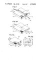
- FIG. 1 is a perspective view of an optical fiber onto which a metallic body will be built up in accordance with the structure and method of this invention.
- FIG. 2 is a perspective view of the same optical fiber of FIG. 1, showing a metal body built up thereon.
- FIG. 3 is a perspective of two of the fibers of FIG. 2 with their bodies machined and lying against a fixture for endwise coupling of the optical fibers.
- FIG. 4 is a side-elevational view, with parts broken away and parts taken in section of a fiber optic structure in accordance with this invention configured as a sensor in fiber optic waveguide link.
- FIG. 5 is a side-elevational view, with parts broken away and parts taken in section showing an optical fiber with a metal body built up thereon and machined as a liquid level sensor, shown not sensing liquid.
- FIG. 6 is a view similar to FIG. 5, showing the device sensing liquid.
- FIG. 7 is a view of structure similar to FIG. 5, but showing a window in the end of the sensor.
- FIG. 8 is a side-elevational view, with parts broken away and parts taken in section of a liquid level sensor in accordance with this invention.
- FIG. 9 is an isometric view of the first assembly of a fiber optic with respect to a base to produce a four port coupler.
- FIG. 10a is a view of the structure of FIG. 9, after the deposition of a metal body to hold the fiber optic in place with respect to the base.
- FIG. 10b is an enlarged plan view, with parts broken away, showing the port in the fiber optic.
- FIG. 10c is an isometric view of the assembled four port coupler.
- FIG. 11 is an isometric view of a mode stripper call made in accordance with this invention, with parts broken away and parts taken in section.
- FIG. 12 is a longitudinal section through a fiber optic structure formed as an extended range temperature sensor.
- FIG. 13 is a perspective view of the metal body on the end of a fiber optic shaped for coupling with a laser light source.
- FIG. 14 is a side-elevational view, with parts broken away and parts taken in section showing the process of and the apparatus for recoating a spliced joint in a metal clad optical fiber.
- FIG. 15 is a side-elevational view of the completed joint formed according to the process of an apparatus of FIG. 14.
- optical fiber 10 is the general indication of a typical coated optical fiber.
- Fiber core 12 is substantially transparent to the optical radiation of interest. It preferably carries an optical cladding 14 and a coating 16.
- Coating 16 can be either an organic material or an inorganic material such as aluminum.
- Such optical fibers can be made sufficiently flexible and optically transmissive to achieve the results required of optical fibers.
- copper body 18 is a built-up structure on coating 16 of fiber 10 when cladding is of an inorganic material such as aluminum.
- copper body 18 is a built-up structure on optical cladding 14 when coating 16 is of an organic material, coating 16 being removed therefrom prior to beginning of the build-up process.
- the length on which the body 18 is to be deposited can be made conductive by vapor deposition of silver or gold as a first step. Copper is particularly suited for the built-up structural body because it can be evenly and easily deposited upon the fiber. An even, localized-force-free deposition process eliminates localized forces which can cause microbending and consequent transmission losses. Other metals would be selected for the built-up structural body when found to be suitable for this even, localized-force-free deposition.
- Copper body 18 is built up by electroplating.
- a suitable electroplating bath is prepared as follows: Two hundred twenty-five grams of copper sulphate are dissolved per liter of water. Fifty-five grams of sulfuric acid are also added per liter to provide the plating.
- a suitable electroplating bath is prepared. Two hundred twenty-five grams of copper sulphate are employed per liter of water. Fifty-five grams of sulfuric acid are also added per liter to provide the copper plating electrolyte.
- Added to the plating electrolyte solution is one-half milliliter of UBAC solution No. 1 per liter of electrolyte. This material is available from Udylite-Omic, 21441 Hoover Road, Warren, MI. 48089. This mixture acts to improve the fineness of the copper grain in the electrolytic build up.
- blackstrap molasses is also useful for the purpose of improving the fineness of the copper grain.
- the plating current be a maximum of 180 milliamperes per square inch. A higher current accelerates the ions in the plating solution and this, in turn, produces random orientation which results in graininess. Currents lower than the maximum current improve the fineness of the copper grain. The preferred current is 90 milliamperes per square inch.
- the plating voltage is from 0 to 3 volts, and the electrolyte temperature is maintained at 70 to 80 degrees F. The concentration of UBAC solution No. 1 in the electrolyte is maintained during the plating operation.
- the plating operation must be carefully performed to minimize stresses in the copper plate body which would cause microbending. Microbending, localized changes in the optical fiber's index of refracting, is caused by forces applied to fiber 10. Copper body 18 is thereby deposited without substantial effect upon fiber 10. The result is that the copper body 18 produces a transmission loss of less than 0.01 decibels in the fiber. Plating continues until the copper body 18 is built up to the desired size.
- FIG. 3 illustrates coupler 20 wherein fiber 10 has its body 18 and another fiber 21 has its body 22 built up in the same manner.
- the bodies 18 and 22 can be plated against fixture 28 at the same time to maintain fiber alignment.
- Bodies 18 and 22 have faces 24 and 26 which are substantially planar and lie at right angles to each other.
- Fixture 28 has corresponding surfaces 30 and 32 also lying at right angles to each other to define the built-up bodies.
- Fibers 10 and 21 respectively extend to the joining faces 34 and 36 where they are ground and polished for optical coupling.
- the cover side 27 of bodies 18 and 22 are machined to permit cover plate contact.
- Coupler 20 is useful over a range of temperatures and especially at high temperatures because the two bodies 18 and 22 have special features.
- the bodies are made of copper, both have the same coefficient of expansion. Therefore, upon temperature change, optical fibers 10 and 21 remain in alignment.
- the deposition of copper is so uniform that over a change in temperature there is not an uneven application of pressure to the fibers 10 and 21 embedded therein. Such uneven expansion would cause uneven forces on the fiber which cause microbending and consequent losses.
- FIG. 4 illustrates coupler 38 which is similar to coupler 20.
- the two fibers 10 and 21 are positioned in an end-to-end relationship and their ends are respectively encased in bodies 18 and 22.
- the bodies are cut and polished at faces 34 and 36 so that the bodies can lie together with the polished ends of fibers 10 and 21 in an optically connected relationship.
- Bodies 18 and 22 may be retained in alignment by means of a suitable fixture, such as fixture 28 illustrated in FIG. 3.
- Coupler 38 further incorporates fiber optic sensing loop 40 which includes source end 42, loop 44 and sensor end 46.
- ends 42 and 46 are both incorporated into body 18, preferably on opposite sides of optical fiber 10.
- Loop 44 is incorporated into body 22 in such a manner that all three interfaces are in alignment at the same time.
- loop 44 can be positioned within one body 22 which has been plated from a solution to become an electroformed body.
- Light source 48 is coupled to source end 42 and light sensor 50 is coupled to sensor end 46.
- continuous detection at sensor 50 it can be determined when connector 38 is opened. This provides security sensing in the connector so that fibers 10 and 21 can be used in a cryptic transmission system.
- sensor 50 can detect when coupler 38 is being tampered with or being opened.
- the use of the fiber optic sensing loop 40 can provide assurance that optical fibers 10 and 21 are in continuity through the coupler to provide confidence in the system for data transmission. Alignment of the several optical fibers in the coupler is assured by holding them in position and electroplating the bodies at the same time.
- the distances between the fibers and the reference faces in several connectors are universal so that the connectors are interchangeable.
- FIGS. 5 and 6 illustrate a liquid level system 64.
- Optical fiber 52 has a core 53, cladding 54, and coating 55.
- Body 56 is built up on optical fiber 52 at its sensing end 57.
- Body 56 is built up in the same way as was previously described for body 18.
- an electrically conductive coating 55 such as aluminum
- this coating can then be used in the plating function for forming body 56 thereupon. If the coating is not electrically conductive or the coating is stripped from the cladding at the sensing end of the fiber, then a vapor deposited layer of silver or gold can be used on the cladding or bare fiber as the starting layer.
- FIGS. 5 and 6 illustrate end faces which maximize internal reflection.
- the end faces form a right angle with respect to each other where the end faces meet on the tip of sensing end 57.
- the upper end (not shown) of the fiber has a light source and a light detector thereon and is called the detector end of the fiber.
- FIG. 5 illustrates sensor end 57 in a position wherein it is exposed to a gaseous environment. As faces 58 and 60 are open to a gaseous environment, the internal reflection returns a large signal, i.e., 60 percent, to the detector.
- FIG. 6 illustrates sensor end 57 wherein end faces 58 and 60 are immersed in liquid 62. This immersion changes the reflection at the end faces. The major portion of the light does not reflect from the end faces, but passes out of fiber 52 and into liquid 62. Thus, when sensor end 57 is immersed in liquid, a much smaller signal is returned to the detector. The smaller return signal indicates that the liquid level is above the sensor end. In this way, the fiber acts as a liquid level sensing system.
- body 56 In addition to holding the fiber so that the faces may be polished on the fiber, body 56 also serves to aid in retaining the sensing end of the fiber in position and protecting it against lateral forces, Thus, the liquid level sensing system 64 returns a substantial signal to the detector end when the sensor ends 57 is not immersed in liquid 62.
- the angle between the end faces may be other than at right angles in order to maximize the difference in signal between the immersed and non-immersed positions of the sensor end.
- coating 55 and optical cladding 54 are exposed.
- coating 55 may react with the liquid in which the sensor end is immersed. In these cases, coating 55 may be terminated before the end of the fiber. Upon formation of the end faces, coating 55 would be protected from the liquid by the electroformed body.
- FIG. 7 illustrates liquid level sensing system 66 and shows only the sensing end of the system.
- Optical fiber 68 has its coating 71 terminated above the end of fiber 68. Coating 71 need not terminate above the end of fiber 68.
- window 72 is butted to the end of fiber 68 and, thereupon, body 74 is plated around optical fiber 68 and window 72. This is to protect fiber 68 against a harsh external environment into which sensor is immersed.
- Deposition of body 74 is the same as was for the previously described deposition of body 18.
- faces 76 and 78 are ground and polished on window 72. The faces are formed at such angles as to maximize internal reflection when the faces are not immersed in liquid and to minimize reflection when they are immersed in liquid.
- optical fiber 68 The detector end (not shown) of optical fiber 68 is opposite the sensor end and is provided with a light source and a detector.
- system 66 returns substantial reflection to the detector when the sensor end is not immersed and returns little reflection to the detector when the sensor end is immersed in liquid.
- System 66 provides window 72 to protect the fiber.
- the angles of the faces are ground and polished to best utilize the laws of total internal reflection.
- the window may be of any suitable material compatible with the liquid and wavelength of interest. Diamond and sapphire are suitable materials in some cases.
- FIG. 8 illustrates another liquid level sensing system 80.
- Vessel 82 has at least side walls and a bottom for retaining liquid 84.
- Liquid level sensor 84 is built into wall 86 of vessel 82.
- Mandrel 88 has optical fiber 90 wrapped spirally around it as a continuous fiber. Connected to opposite ends of optical fiber 90 are light source 92, which may be a light-emitting diode, and light detector 94.
- Optical fiber 90 is wrapped around mandrel 88 with a spacing between two adjacent fibers being the smallest increment in liquid level to be detected. This optical fiber-wrapped-mandrel assembly is then coated with a body of material 96 to bury fiber 90 and rigidly hold it in place.
- a coating material depends on the harshness of the environment to which liquid level sensing system 80 will be exposed. In accordance with this invention, it is preferred that the body of material 96 be built up by electroplating, the same way as previously described for body 18. Copper is a suitable material for some environments, or other materials which can be plated can be employed as body 96.
- optical fiber 90 is composed of core 91 covered by optical cladding 93.
- the fiber core is of any conventional core material, such as quartz glass, and the cladding is a glass cladding which reflects light back into the core. Thus, some of the light passes through the cladding, and this light will be stripped away where liquid comes into contact with the polished cladding.
- the liquid level sensing system of FIG. 8 has a restriction on the diameter of mandrel 88.
- the diameter of mandrel 88 must be chosen so that it is large enough to prevent the rapid loss of optical power in the first few turns of optical fiber 90 around mandrel 88 with a small diameter mandrel, light is radiated into the optical cladding 93 of the first few turns of fiber 40 resulting in the optical power loss.
- With large diameter mandrels and high numerical aperture fibers the problem is minimized.
- a higher numerical aperture is required in the fiber to minimize the radiation loss.
- the mandrel diameter increases, the requirement of a higher numerical aperture decreases.
- the numerical aperture is inversely proportional to the mandrel diameter.
- an optical fiber with a fifteen micron core and glass cladding and having a length of six feet can be wound around the mandrel with four exposed turns on the sensor side 98.
- an optical fiber having a numerical aperture of 0.2 was used.
- liquid level sensing system 80 can be considered a quasianalog system. Closer spacing of the turns provides for detection of smaller increments in liquid level height and more turns provides for a greater range in detection.
- FIG. 10c shows rigid four port fiber optic directional coupler 100. It is constructed of coupler halves 102 and 104. The completed coupler half 102 is shown in FIGS. 10a and 10b, while an intermediate stage of the construction is shown in FIG. 9.
- substrate 106 has a cut groove 108 below face 110 thereof. Groove 108 has a gentle radius of curvature, convex toward the top, as seen in FIG. 9.
- Optical fiber 112 is laid lengthwise in groove 108. When optical fiber 112 has an organic or otherwise non-electrically conductive coating on its cladding, the coating is stripped, thereby exposing the cladding. Stripped section 114, wherein the cladding is exposed, is illustrated in FIG. 9.
- optical fiber 112 when optical fiber 112 is coated with aluminum, such coating may be left on or may be removed.
- the stripped section 114 lies against the highest part of the curved surface of groove 108, and ends 116 and 118 extend away from face 110 of substrate 106 for connection purposes. While stripped section 114 and the rest of optical fiber 112 are held in place, groove 108 is filled by plating, in the manner described with respect to FIG. 2. Plated body 120 therefore fills groove 108, as is indicated in FIG. 10a.
- the top of the combined structure of substrate 106, optical fiber 112, and body 120 is ground and polished on top face 122. The grinding and polishing process continues until the core in single-mode optical fibers is totally exposed.
- the grinding and polishing may be done to either partially or totally expose the core.
- ground and polished face 122 nearly exposes core 124 in this single-mode case and exposes cladding 126. This completes coupler half 102 of which coupler half 104 is identical.
- Directional coupler 100 has greater durability, stability, and provides less change over temperature fluctuations than previously constructed couplers. The reason for this is that the plated body applies uniform pressure over the fiber to minimize microbending, even during temperature changes.
- the embodiment of a substantial length of the optical fiber 112 into body 120 also provides strain relief to the fiber. This serves to minimize stresses at the active area which is exposed by polishing.
- Mode-stripper 130 shown in FIG. 11 strips signals at the exterior of the optical cladding by changing the characteristics at the surface of the optical cladding.
- Optical fiber 132 comprises optical core 134 and glass cladding 136.
- Coating 138 is applied to the optical fiber 132 on glass cladding 136.
- the coating may be organic or may be metallic, such as aluminum, as described with respect to FIGS. 1 and 2.
- the coating 138 is removed to provide an uncoated section 140.
- Body 142 of the mode-stripper 130 is built up around uncoated section 140.
- Stripper cavity 144 is provided by building up a suitable wax matrix on the fiber. Screws 146 and 148 are mounted in the wax matrix.
- body 142 is built up by electro-deposition, the same way as was previously described for body 18.
- the uncoated fiber, the wax matrix, and plastic screws 146 and 148 receive a vapor-deposited layer of silver or gold. This deposited layer provides for even electro-deposition of metal which will make up body 142.
- screws 146 and 148 are removed. Thereupon, the wax matrix can be removed by solvent wash so that cavity 144 is created. Cavity 144 is, thereupon, filled with the proper mode-stripper compound, usually a high index oil. Screws 146 and 148 are replaced. It permanent replacement is desired, metallic screws can be used and soldered in place. Furthermore, if desired, electro-deposited material can be placed over the metal screws to completely cover them.
- Mode-stripper 130 is shown as being formed along the length of optical fiber 132. This construction can be incorporated into a coupling if an adjoining coupling is desired. Thus, mode-stripper 130 can be made into body 18 of coupling 20 of FIG. 3.
- Temperature sensor 150 is illustrated in FIG. 12.
- Clad optical fiber 152 carries coating 154. The coating is stripped in the temperature-sensing region 156.
- Body 158 is built up in the temperature-sensing region and overlaps coating 154.
- clad optical fiber 152 can be of quartz and body 158 can be of nickel or a high-temperature, platable alloy. Body 158 is built up in the same way as was previously described for body 18. Coating 154 is stripped far enough back so that it is not subject to degradation from temperature. When an incandescent point 160 emits light, some of the light passes toward detector 162 which receives the light passing upward in the fiber.
- the tip of sensor 150 is ground and polished to become a plurality of reflecting faces 164 and 166. Light passing down the fiber toward the lower end, where reflecting faces 164 and 166 are located, is reflected back toward detector 162. This reflection at the tip increases the useful signal by at least 40 percent.
- the built-up body 158 is of a suitable material for the selected temperature range and serves to protect the portion of the fiber in the high-temperature region. The total internal reflection which occurs at the tip of the sensor enhances its utility.
- FIG. 13 illustrates body 170 built up on an optical fiber.
- Optical fiber 169 comprises core 172, cladding 174 and coating, if any, 176.
- the coating may be aluminum, may be organic, or may be absent.
- the exterior of the fiber is coated with a conductive material.
- the vapor deposition of silver or gold onto the exterior serves as an electro-deposition starting point, as previously described.
- a body 170 is built up on the end of the fiber, as illustrated, in the same manner as the electro-deposition of body 18.
- body 170 When body 170 is built up, it serves to protect the fiber, and, when the electro-deposition is properly carried out, there is a minimum of stresses on the fiber so that microbending is minimized.
- faces 178 and 180 are ground and polished on the fiber and the body. These faces are configured for optimum coupling of the maximum amount of light emanating from a light source into the fiber.
- a light source is illustrated in FIG. 13 as light source 182.
- Light source 182 may be a laser diode which has a light output pattern that matches core 172 of fiber 169. Light source 182 is positioned with its emission directed toward fiber 169. Fiber 169 can then be positioned with respect to light source 182 and clamped in that position by employing body 170.
- the metal built-up body 170 provides a one-time built-up structure which provides optimum support for processing, i.e., grinding and polishing; it permits reprocessing of the faces, if necessary; and it provides a stable support for final mounting.
- FIGS. 14 and 15 show coated optical fibers 184 and 186.
- the coating is stripped back to provide bare but glass-clad fibers 188 and 190.
- the fibers are joined by fusing at splice 192, a technique well known in the art of fiber optics. After the fusing at splice 192 is completed, fixture halves 194 and 195 are clamped around the bare fiber at the spliced area. A far fixture half 194 and a similar near half 195 are clamped together to closely embrace and seal against coated fibers 184 and 186.
- the metal coating of the fibers is cathodically connected and then fixture 194 is filled with plating solution 196 of the character previously described with respect to the build up of body 18.
- Anode 198 is immersed in the plating solution and plating current is provided. Copper builds up from the aluminum coating toward sprue 200. With the continued application of plating current, the plated copper faces build up toward each other and join in the center beneath the sprue and the plated metal works itself into the sprue opening.
- the result is body 202.
- fixture halves 194 and 195 are removed and body 202 is smoothed as necessary to provide an outer surface which is the same diameter as coated fibers 184 and 186.
- splice 192 provides a reflection signal so that such splices may be placed in the fiber at known lengths for calibration purposes. Since the spliced fiber is now the same diameter as the original coated fiber, it may be wrapped on a mandrel with a minimum amount of microbending and radiation losses.
Abstract
A fiber optic structure comprising an optical fiber having a body of material deposited upon the exterior surface such that the body of material is sufficiently strong and rigid to permit processing of the fiber for various fiber optics applications. The process for forming the fiber optic structure involves the electroplating of a body of material upon the exterior surface of the optical fiber which is to be processed. A built-up body of fiber allows coupling structures to be created. The built-up body enables the fiber to be used as liquid level sensors and other types of mode strippers.
Description
This is a continuation of application Ser. No. 06/572,734, filed 01/20/84.
Optical fiber has electro-deposited thereon a metal body which permits the fiber to be mechanically acted upon by machining, positioning, or handling the metal body.
Fiber optic waveguides are small and fragile. It is important that the waveguides be firmly supported at least at their ends so that they can be ground and polished with facets or other surfaces which are optimum for coupling light into the fiber or for coupling the fiber with respect to another optical structure such as another optical fiber, a detector, or an integrated optic waveguide. In the past, epoxy adhesive has been employed for attaching a fiber optic waveguide to a surface for the purpose of building a coupling device for the end of the fiber, including polishing of the fiber end. One of the problems of this attachment is that the dimensional changes in the hardening epoxy adhesive cause external forces on the fiber optic waveguide. These forces cause microbending in the optical fiber resulting in significant signal losses. Microbending, localized changes in the optical fiber's index of refraction, must be minimized in order to maximize the signal and the signal-to-noise ratio. Thus, there is need for a structure which can be built up onto an optical fiber to permit handling of the optical fiber and to permit machining and otherwise processing the end of the optical fiber to enhance coupling and the like.
In order to aid in the understanding of this invention, it can be stated in essentially summary form that it is directed to a fiber optic structure and the method of making the fiber optic structure. The fiber optic structure comprises the depositing upon the exterior of the fiber a body of material which is sufficiently strong and rigid to permit machining and other handling of the fiber. The body of material should have a thermal coefficient of expansion substantially the same as that of the fiber optic material to minimize microbending and consequent microbending losses upon temperature change.
It is a purpose and advantage of this invention to provide a method of depositing a body on the exterior of a fiber optic waveguide in order to permit handling, machining, and connecting of the waveguide to other optical parts.
It is a further purpose and advantage of this invention to provide a metallic body deposited on a fiber optical waveguide in such a manner that the body minimizes microbending losses and permits machining and attachment of the fiber optic for optical interconnection therewith.
Other purposes and advantages of this invention will become apparent from a study of the following portion of the specification, the claims, and the attached drawings.
FIG. 1 is a perspective view of an optical fiber onto which a metallic body will be built up in accordance with the structure and method of this invention.
FIG. 2 is a perspective view of the same optical fiber of FIG. 1, showing a metal body built up thereon.
FIG. 3 is a perspective of two of the fibers of FIG. 2 with their bodies machined and lying against a fixture for endwise coupling of the optical fibers.
FIG. 4 is a side-elevational view, with parts broken away and parts taken in section of a fiber optic structure in accordance with this invention configured as a sensor in fiber optic waveguide link.
FIG. 5 is a side-elevational view, with parts broken away and parts taken in section showing an optical fiber with a metal body built up thereon and machined as a liquid level sensor, shown not sensing liquid.
FIG. 6 is a view similar to FIG. 5, showing the device sensing liquid.
FIG. 7 is a view of structure similar to FIG. 5, but showing a window in the end of the sensor.
FIG. 8 is a side-elevational view, with parts broken away and parts taken in section of a liquid level sensor in accordance with this invention.
FIG. 9 is an isometric view of the first assembly of a fiber optic with respect to a base to produce a four port coupler.
FIG. 10a is a view of the structure of FIG. 9, after the deposition of a metal body to hold the fiber optic in place with respect to the base.
FIG. 10b is an enlarged plan view, with parts broken away, showing the port in the fiber optic.
FIG. 10c is an isometric view of the assembled four port coupler.
FIG. 11 is an isometric view of a mode stripper call made in accordance with this invention, with parts broken away and parts taken in section.
FIG. 12 is a longitudinal section through a fiber optic structure formed as an extended range temperature sensor.
FIG. 13 is a perspective view of the metal body on the end of a fiber optic shaped for coupling with a laser light source.
FIG. 14 is a side-elevational view, with parts broken away and parts taken in section showing the process of and the apparatus for recoating a spliced joint in a metal clad optical fiber.
FIG. 15 is a side-elevational view of the completed joint formed according to the process of an apparatus of FIG. 14.
In FIG. 1, optical fiber 10 is the general indication of a typical coated optical fiber. Fiber core 12 is substantially transparent to the optical radiation of interest. It preferably carries an optical cladding 14 and a coating 16. Coating 16 can be either an organic material or an inorganic material such as aluminum. Such optical fibers can be made sufficiently flexible and optically transmissive to achieve the results required of optical fibers.
Referring to FIG. 2, copper body 18 is a built-up structure on coating 16 of fiber 10 when cladding is of an inorganic material such as aluminum. Alternatively, copper body 18 is a built-up structure on optical cladding 14 when coating 16 is of an organic material, coating 16 being removed therefrom prior to beginning of the build-up process.
When the optical cladding 14 is the exterior or material of the fiber, the length on which the body 18 is to be deposited can be made conductive by vapor deposition of silver or gold as a first step. Copper is particularly suited for the built-up structural body because it can be evenly and easily deposited upon the fiber. An even, localized-force-free deposition process eliminates localized forces which can cause microbending and consequent transmission losses. Other metals would be selected for the built-up structural body when found to be suitable for this even, localized-force-free deposition.
It is critical to the plating that the plating current be a maximum of 180 milliamperes per square inch. A higher current accelerates the ions in the plating solution and this, in turn, produces random orientation which results in graininess. Currents lower than the maximum current improve the fineness of the copper grain. The preferred current is 90 milliamperes per square inch. The plating voltage is from 0 to 3 volts, and the electrolyte temperature is maintained at 70 to 80 degrees F. The concentration of UBAC solution No. 1 in the electrolyte is maintained during the plating operation.
The plating operation must be carefully performed to minimize stresses in the copper plate body which would cause microbending. Microbending, localized changes in the optical fiber's index of refracting, is caused by forces applied to fiber 10. Copper body 18 is thereby deposited without substantial effect upon fiber 10. The result is that the copper body 18 produces a transmission loss of less than 0.01 decibels in the fiber. Plating continues until the copper body 18 is built up to the desired size.
The built-up structural body is useful for creating structures of various utility and for use of the fiber 10 in various different applications. FIG. 3 illustrates coupler 20 wherein fiber 10 has its body 18 and another fiber 21 has its body 22 built up in the same manner. The bodies 18 and 22 can be plated against fixture 28 at the same time to maintain fiber alignment. Bodies 18 and 22 have faces 24 and 26 which are substantially planar and lie at right angles to each other. Fixture 28 has corresponding surfaces 30 and 32 also lying at right angles to each other to define the built-up bodies. Fibers 10 and 21 respectively extend to the joining faces 34 and 36 where they are ground and polished for optical coupling. The cover side 27 of bodies 18 and 22 are machined to permit cover plate contact. When bodies 18 and 22 are positioned against the fixture with their adjoining faces 34 and 36 in contact, then the two fibres 10 and 21 are in end-to-end optical coupling. Cover plate 37 holds them in place. Since optical fibers 10 and 21 are a fixed distance from the reference faces which adjoin the fixture, the coupling may be disassembled and reassembled with proper coupling.
FIG. 4 illustrates coupler 38 which is similar to coupler 20. Again, the two fibers 10 and 21 are positioned in an end-to-end relationship and their ends are respectively encased in bodies 18 and 22. The bodies are cut and polished at faces 34 and 36 so that the bodies can lie together with the polished ends of fibers 10 and 21 in an optically connected relationship. Bodies 18 and 22 may be retained in alignment by means of a suitable fixture, such as fixture 28 illustrated in FIG. 3. Coupler 38 further incorporates fiber optic sensing loop 40 which includes source end 42, loop 44 and sensor end 46. As is seen in FIG. 4, ends 42 and 46 are both incorporated into body 18, preferably on opposite sides of optical fiber 10. Loop 44 is incorporated into body 22 in such a manner that all three interfaces are in alignment at the same time. In the present state of the art, metal-coated fibers can withstand very small bends in the fiber and survive in the bent condition for long periods of time. Accordingly, loop 44 can be positioned within one body 22 which has been plated from a solution to become an electroformed body.
Light source 48 is coupled to source end 42 and light sensor 50 is coupled to sensor end 46. By use of continuous detection at sensor 50, it can be determined when connector 38 is opened. This provides security sensing in the connector so that fibers 10 and 21 can be used in a cryptic transmission system. Thus, sensor 50 can detect when coupler 38 is being tampered with or being opened. Even in systems without the need for cryptic security, the use of the fiber optic sensing loop 40 can provide assurance that optical fibers 10 and 21 are in continuity through the coupler to provide confidence in the system for data transmission. Alignment of the several optical fibers in the coupler is assured by holding them in position and electroplating the bodies at the same time. In addition, it is preferable that the distances between the fibers and the reference faces in several connectors are universal so that the connectors are interchangeable.
FIGS. 5 and 6 illustrate a liquid level system 64. Optical fiber 52 has a core 53, cladding 54, and coating 55. Body 56 is built up on optical fiber 52 at its sensing end 57. Body 56 is built up in the same way as was previously described for body 18. When there is an electrically conductive coating 55, such as aluminum, on optical cladding 54 this coating can then be used in the plating function for forming body 56 thereupon. If the coating is not electrically conductive or the coating is stripped from the cladding at the sensing end of the fiber, then a vapor deposited layer of silver or gold can be used on the cladding or bare fiber as the starting layer.
When body 56 is built up, its sensing end 57 is ground and polished into end faces which maximize internal reflection. Although as many end faces as desired can be used, two such end faces 58 and 60 are illustrated in FIGS. 5 and 6. The end faces form a right angle with respect to each other where the end faces meet on the tip of sensing end 57. The upper end (not shown) of the fiber has a light source and a light detector thereon and is called the detector end of the fiber. FIG. 5 illustrates sensor end 57 in a position wherein it is exposed to a gaseous environment. As faces 58 and 60 are open to a gaseous environment, the internal reflection returns a large signal, i.e., 60 percent, to the detector.
FIG. 6 illustrates sensor end 57 wherein end faces 58 and 60 are immersed in liquid 62. This immersion changes the reflection at the end faces. The major portion of the light does not reflect from the end faces, but passes out of fiber 52 and into liquid 62. Thus, when sensor end 57 is immersed in liquid, a much smaller signal is returned to the detector. The smaller return signal indicates that the liquid level is above the sensor end. In this way, the fiber acts as a liquid level sensing system.
In addition to holding the fiber so that the faces may be polished on the fiber, body 56 also serves to aid in retaining the sensing end of the fiber in position and protecting it against lateral forces, Thus, the liquid level sensing system 64 returns a substantial signal to the detector end when the sensor ends 57 is not immersed in liquid 62. The angle between the end faces may be other than at right angles in order to maximize the difference in signal between the immersed and non-immersed positions of the sensor end.
As end faces are made on sensor end 57, coating 55 and optical cladding 54 are exposed. In some cases, coating 55 may react with the liquid in which the sensor end is immersed. In these cases, coating 55 may be terminated before the end of the fiber. Upon formation of the end faces, coating 55 would be protected from the liquid by the electroformed body.
FIG. 7 illustrates liquid level sensing system 66 and shows only the sensing end of the system. Optical fiber 68 has its coating 71 terminated above the end of fiber 68. Coating 71 need not terminate above the end of fiber 68. In system 66, window 72 is butted to the end of fiber 68 and, thereupon, body 74 is plated around optical fiber 68 and window 72. This is to protect fiber 68 against a harsh external environment into which sensor is immersed. Deposition of body 74 is the same as was for the previously described deposition of body 18. When deposition is complete, faces 76 and 78 are ground and polished on window 72. The faces are formed at such angles as to maximize internal reflection when the faces are not immersed in liquid and to minimize reflection when they are immersed in liquid.
The detector end (not shown) of optical fiber 68 is opposite the sensor end and is provided with a light source and a detector. Thus, system 66 returns substantial reflection to the detector when the sensor end is not immersed and returns little reflection to the detector when the sensor end is immersed in liquid. System 66 provides window 72 to protect the fiber. The angles of the faces are ground and polished to best utilize the laws of total internal reflection. The window may be of any suitable material compatible with the liquid and wavelength of interest. Diamond and sapphire are suitable materials in some cases.
FIG. 8 illustrates another liquid level sensing system 80. Vessel 82 has at least side walls and a bottom for retaining liquid 84. Liquid level sensor 84 is built into wall 86 of vessel 82. Mandrel 88 has optical fiber 90 wrapped spirally around it as a continuous fiber. Connected to opposite ends of optical fiber 90 are light source 92, which may be a light-emitting diode, and light detector 94. Optical fiber 90 is wrapped around mandrel 88 with a spacing between two adjacent fibers being the smallest increment in liquid level to be detected. This optical fiber-wrapped-mandrel assembly is then coated with a body of material 96 to bury fiber 90 and rigidly hold it in place. The choice of a coating material depends on the harshness of the environment to which liquid level sensing system 80 will be exposed. In accordance with this invention, it is preferred that the body of material 96 be built up by electroplating, the same way as previously described for body 18. Copper is a suitable material for some environments, or other materials which can be plated can be employed as body 96. Once the fiber has been protected by body 96, sensor side 98 is ground and polished so that optical cladding 93 of optical fiber 90 is exposed and fiber core 91 is fairly close to, but below the polished surface of sensor side 98. After the cladding is exposed by polishing, liquid level sensor 85 is placed in the side of vessel 82, as indicated in FIG. 8.
In liquid level sensing system 80 of FIG. 8, optical fiber 90 is composed of core 91 covered by optical cladding 93. The fiber core is of any conventional core material, such as quartz glass, and the cladding is a glass cladding which reflects light back into the core. Thus, some of the light passes through the cladding, and this light will be stripped away where liquid comes into contact with the polished cladding.
The liquid level sensing system of FIG. 8 has a restriction on the diameter of mandrel 88. The diameter of mandrel 88 must be chosen so that it is large enough to prevent the rapid loss of optical power in the first few turns of optical fiber 90 around mandrel 88 with a small diameter mandrel, light is radiated into the optical cladding 93 of the first few turns of fiber 40 resulting in the optical power loss. With large diameter mandrels and high numerical aperture fibers, the problem is minimized. When a smaller mandrel diameter is used, a higher numerical aperture is required in the fiber to minimize the radiation loss. As the mandrel diameter increases, the requirement of a higher numerical aperture decreases. As a general rule, the numerical aperture is inversely proportional to the mandrel diameter.
As a specific example, with a mandrel of ten inches in diameter, an optical fiber with a fifteen micron core and glass cladding and having a length of six feet can be wound around the mandrel with four exposed turns on the sensor side 98. For such purpose, an optical fiber having a numerical aperture of 0.2 was used. Using a helium-neon laser and a silicon detector, when none of the exposed cladding portions on the sensor side 98 are immersed in water, the signal arriving at detector 94 would be about 90 percent of the light emitted by source 92.
As the light from the core is radiated into the cladding, there is a substantial amount of power which can be mode-stripped from cladding 93 when adjacent the liquid. The drop in the optical power of detector 94 represents the liquid level. Liquid 84, monitored in vessel 82, is the mode-stripper. As liquid 84 rises in the vessel, it reduces the light detected at detector 94 by about 3 percent for each of the exposed portions of cladding 93 which is covered by liquid 84. In between each loop a bend is introduced to radiate more light into cladding 93. Since only one detector is employed in response to five different liquid levels in the example illustrated, liquid level sensing system 80 can be considered a quasianalog system. Closer spacing of the turns provides for detection of smaller increments in liquid level height and more turns provides for a greater range in detection.
FIG. 10c shows rigid four port fiber optic directional coupler 100. It is constructed of coupler halves 102 and 104. The completed coupler half 102 is shown in FIGS. 10a and 10b, while an intermediate stage of the construction is shown in FIG. 9. In FIG. 9, substrate 106 has a cut groove 108 below face 110 thereof. Groove 108 has a gentle radius of curvature, convex toward the top, as seen in FIG. 9. Optical fiber 112 is laid lengthwise in groove 108. When optical fiber 112 has an organic or otherwise non-electrically conductive coating on its cladding, the coating is stripped, thereby exposing the cladding. Stripped section 114, wherein the cladding is exposed, is illustrated in FIG. 9. However, when optical fiber 112 is coated with aluminum, such coating may be left on or may be removed. In FIG. 9, the stripped section 114 lies against the highest part of the curved surface of groove 108, and ends 116 and 118 extend away from face 110 of substrate 106 for connection purposes. While stripped section 114 and the rest of optical fiber 112 are held in place, groove 108 is filled by plating, in the manner described with respect to FIG. 2. Plated body 120 therefore fills groove 108, as is indicated in FIG. 10a. The top of the combined structure of substrate 106, optical fiber 112, and body 120 is ground and polished on top face 122. The grinding and polishing process continues until the core in single-mode optical fibers is totally exposed. In multi-mode optical fibers, the grinding and polishing may be done to either partially or totally expose the core. As is seen in FIG. 10b, ground and polished face 122 nearly exposes core 124 in this single-mode case and exposes cladding 126. This completes coupler half 102 of which coupler half 104 is identical.
When the two coupler halves 102 and 104 are placed together in face-to-face relationship with the core and cladding of their respective optical fibers adjoining, they form a stable four port directional coupler as illustrated in FIG. 10c. Directional coupler 100 has greater durability, stability, and provides less change over temperature fluctuations than previously constructed couplers. The reason for this is that the plated body applies uniform pressure over the fiber to minimize microbending, even during temperature changes. The embodiment of a substantial length of the optical fiber 112 into body 120 also provides strain relief to the fiber. This serves to minimize stresses at the active area which is exposed by polishing.
Mode-stripper 130 shown in FIG. 11 strips signals at the exterior of the optical cladding by changing the characteristics at the surface of the optical cladding. Optical fiber 132 comprises optical core 134 and glass cladding 136. Coating 138 is applied to the optical fiber 132 on glass cladding 136. The coating may be organic or may be metallic, such as aluminum, as described with respect to FIGS. 1 and 2. To create mode-stripper 130, the coating 138 is removed to provide an uncoated section 140. Body 142 of the mode-stripper 130 is built up around uncoated section 140. Stripper cavity 144 is provided by building up a suitable wax matrix on the fiber. Screws 146 and 148 are mounted in the wax matrix. Thereupon, body 142 is built up by electro-deposition, the same way as was previously described for body 18. In order to properly plate those areas which are not electrically conductive, the uncoated fiber, the wax matrix, and plastic screws 146 and 148 (and coating 138 if it is not conductive) receive a vapor-deposited layer of silver or gold. This deposited layer provides for even electro-deposition of metal which will make up body 142.
After body 142 is built up to the desired size, screws 146 and 148 are removed. Thereupon, the wax matrix can be removed by solvent wash so that cavity 144 is created. Cavity 144 is, thereupon, filled with the proper mode-stripper compound, usually a high index oil. Screws 146 and 148 are replaced. It permanent replacement is desired, metallic screws can be used and soldered in place. Furthermore, if desired, electro-deposited material can be placed over the metal screws to completely cover them.
Mode-stripper 130 is shown as being formed along the length of optical fiber 132. This construction can be incorporated into a coupling if an adjoining coupling is desired. Thus, mode-stripper 130 can be made into body 18 of coupling 20 of FIG. 3.
The materials used in the temperature sensor are based on the temperature to be sensed. Quartz begins to emit usefully detectable visable radiation at about 600 degrees C. (while at lower temperatures other types of radiation is detectable) and softens at 1,660 degrees C. There is an increasing intensity of the emitted radiation from this lower limit to this upper limit. Thus, clad optical fiber 152 can be of quartz and body 158 can be of nickel or a high-temperature, platable alloy. Body 158 is built up in the same way as was previously described for body 18. Coating 154 is stripped far enough back so that it is not subject to degradation from temperature. When an incandescent point 160 emits light, some of the light passes toward detector 162 which receives the light passing upward in the fiber. The tip of sensor 150 is ground and polished to become a plurality of reflecting faces 164 and 166. Light passing down the fiber toward the lower end, where reflecting faces 164 and 166 are located, is reflected back toward detector 162. This reflection at the tip increases the useful signal by at least 40 percent.
Other temperature ranges are possible by employing an insert 168 at the tip which emits an optical signal over the desired temperature range. The built-up body 158 is of a suitable material for the selected temperature range and serves to protect the portion of the fiber in the high-temperature region. The total internal reflection which occurs at the tip of the sensor enhances its utility.
Holding an optical fiber for processing, during processing, and holding it during coupling to a light source also finds a solution in the electroplating of a body of material. FIG. 13 illustrates body 170 built up on an optical fiber. Optical fiber 169 comprises core 172, cladding 174 and coating, if any, 176. The coating may be aluminum, may be organic, or may be absent. When the coating is organic or absent, the exterior of the fiber is coated with a conductive material. The vapor deposition of silver or gold onto the exterior serves as an electro-deposition starting point, as previously described. Thereupon, a body 170 is built up on the end of the fiber, as illustrated, in the same manner as the electro-deposition of body 18.
When body 170 is built up, it serves to protect the fiber, and, when the electro-deposition is properly carried out, there is a minimum of stresses on the fiber so that microbending is minimized. After deposition of body 170, faces 178 and 180 are ground and polished on the fiber and the body. These faces are configured for optimum coupling of the maximum amount of light emanating from a light source into the fiber. A light source is illustrated in FIG. 13 as light source 182. Light source 182 may be a laser diode which has a light output pattern that matches core 172 of fiber 169. Light source 182 is positioned with its emission directed toward fiber 169. Fiber 169 can then be positioned with respect to light source 182 and clamped in that position by employing body 170. This protects the fiber as well as positioning and securing it with respect to the light source. The metal built-up body 170 provides a one-time built-up structure which provides optimum support for processing, i.e., grinding and polishing; it permits reprocessing of the faces, if necessary; and it provides a stable support for final mounting.
A further embodiment of the invention disclosed therein is the use of the electroplating process to coat optical fibers after they have been spliced thereby protecting the splice and providing a uniform optical fiber. FIGS. 14 and 15 show coated optical fibers 184 and 186. The coating is stripped back to provide bare but glass-clad fibers 188 and 190. The fibers are joined by fusing at splice 192, a technique well known in the art of fiber optics. After the fusing at splice 192 is completed, fixture halves 194 and 195 are clamped around the bare fiber at the spliced area. A far fixture half 194 and a similar near half 195 are clamped together to closely embrace and seal against coated fibers 184 and 186. The metal coating of the fibers is cathodically connected and then fixture 194 is filled with plating solution 196 of the character previously described with respect to the build up of body 18. Anode 198 is immersed in the plating solution and plating current is provided. Copper builds up from the aluminum coating toward sprue 200. With the continued application of plating current, the plated copper faces build up toward each other and join in the center beneath the sprue and the plated metal works itself into the sprue opening. The result is body 202. When the build up of body 202 is completed, fixture halves 194 and 195 are removed and body 202 is smoothed as necessary to provide an outer surface which is the same diameter as coated fibers 184 and 186. This splicing operation is useful in creating long lengths of optical fiber, lengths beyond the capability of present production of single fibers. In addition, splice 192 provides a reflection signal so that such splices may be placed in the fiber at known lengths for calibration purposes. Since the spliced fiber is now the same diameter as the original coated fiber, it may be wrapped on a mandrel with a minimum amount of microbending and radiation losses.
This invention has been described in its presently contemplated best mode, and it is clear that it is susceptible to numerous modifications, modes and embodiments within the ability of those skilled in the art and without the exercise of the inventive faculty. Accordingly, the scope of this invention is defined by the scope of the following claims.
Claims (28)
1. A fiber optic structure comprising:
an optical fiber; and
a metallic body of radial thickness on the order of 0.003" or above, deposited on said fiber and surrounding said fiber for strengthening and rigidizing said fiber within said metallic body so that said metallic body and said fiber may be acted upon and positioned for optical purposes, with substantial reduction of microbending losses in said fiber.
2. The fiber optic structure of claim 1 wherein said metallic body is an electro-deposited body.
3. The fiber optic structure of claim 2 wherein said electro-deposited body is copper body.
4. The fiber optic structure of claim 3 wherein said body is positioned adjacent the end of the optical fiber.
5. The fiber optic structure of claim 1 wherein said body is positioned adjacent the end of the optical fiber.
6. A fiber optic structure comprising:
at least one optical fiber; and
at least one metallic body deposited on a respective part of said fiber for rigidizing said respective part of said fiber encased within said at least one metallic body so that said fiber may be acted upon and positioned for optical purposes, said at least one metallic body having a radial thickness at least on the order of 0.003", and being processed at an exterior surface area so as to make said respective part of said fiber encased within, optically accessible at said surface.
7. The fiber optic structure of claim 6 wherein said structure is a liquid sensor with said optical fiber being for connection to a source and a detector, said exterior surface area being configured at an angle such that internal reflection from said exterior surface area is promoted when said exterior surface are is not immersed in liquid and inhibited when said exterior surface area is immersed in liquid.
8. The fiber optic structure of claim 6 wherein said structure is a temperature sensor, with said exterior surface area reflecting light produced within said fiber as a function of temperature.
9. A fiber optic structure comprising:
first and second optical fibers; and
first and second metallic bodies respectively deposited on and encasing respective parts of said first and second optical fibers, said first and second bodies each having an exterior surface area with said respective part of said first and second optical fibers respectively exposed at said respective exterior surface area, said first and said second bodies each having a radial thickness at least on the order of 0.003" and being positioned so that said first and second fibers are optically connected, said first and second metallic bodies being deposited in a manner which substantially avoids undesired alteration of the respective indices of refraction of said first and second optical fibers.
10. The fiber optic structure of claim 9 wherein both said first and second metallic bodies are electro-deposited metallic bodies.
11. The fiber optic structure of claim 10 wherein said first and second electro-deposited bodies are copper bodies.
12. The fiber optic structure of claim 11 wherein the ends of said first and second fibers are respectively exposed at said exterior surface areas of said bodies and said bodies are positioned for end-to-end optical connection between said first and second fibers.
13. The fiber optic structure of claim 9 wherein there is a looped optical fiber in said second body and there is a source and a detector fiber within said first body, all of said fibers being positioned so that when said first and second optical fibers are in alignment, said looped fiber interconnects said source and said detector fibers so that when said looped fiber does not have continuity, said first and second fibers lack continuity.
14. The fiber optic structure of claim 9 wherein said first and second optical fibers are exposed at said faces intermediate the ends of said optical fibers so that positioning of said faces for coupling of said optical fibers provides a four port coupler.
15. A fiber optic structure comprising:
first and second optical fibers each having an end;
first and second metallic bodies respectively electro-deposited on said ends of first and second optical fibers, said first and second bodies having polished adjoining faces wherein said ends of said optical fibers are exposed, said first and second bodies each also having two reference faces; and
a fixture, said fixture being shaped so that when said reference faces of said bodies lie in said fixture, said first and second optical fibers are in endwise optical alignment.
16. The fiber optic structure of claim 15 wherein both said first and second metallic bodies are formed of electro-deposited copper.
17. A fiber optic structure comprising:
first and second optical fibers, each having an end;
first and second metallic bodies respectively carried on said first and second optical fibers adjacent their ends, said first and second bodies respectively having adjoining faces with said first and second optical fibers exposed at said adjoining faces, said first and second metallic bodies being positionable so that said first and second optical fibers are in optical alignment;
a source optical fiber and a detector optical fiber being respectively for connection to a light source and a light detector, said source fiber and said detector fiber each having ends and being positioned within said first body so that said ends are exposed at said face of said first body; and
a loop optical fiber having ends, said loop optical fiber being at least partially positioned within said second body and having its ends exposed at said face of said second body, said source, said loop and said detector optical fibers being positioned so that they are in optical continuity when said first and second optical fibers are in optical continuity.
18. The fiber optic structure of claim 17 wherein both said first and second bodies are formed of electro-deposited copper.
19. A fiber optic structure comprising:
a mandrel;
an optical fiber having a source end and a detector end, said optical fiber being wrapped in a plurality of turns around said mandrel, said source end being for connection to a light source and said detector end being for connection to a light detector;
said optical fiber having an optical cladding;
a built-up metallic body deposited around said fiber; and
said body having a sensor face, the cladding on said fiber being exposed at said sensor face so that as the exposed portions of cladding are successively immersed in liquid, the amount of light arriving at the detector end is decreased.
20. The fiber optic structure of claim 19 wherein a light source is connected to said source end and a light detector is connected to said detector end of said fiber.
21. The fiber optic structure of claim 20 wherein at least a portion of said body is positioned within a tank so that as liquid rises in said tank, said exposed cladding portions are successively covered to reduce light output at the detector end of said fiber.
22. The fiber optic structure of claim 19 wherein at least a portion of said body is positioned within a tank so that as liquid rises in said tank, said exposed cladding portions are successively covered to reduce light output at the detector end of said fiber.
23. A four-port fiber optic coupler comprising:
first and second optical fibers, each of said fibers having ends;
first and second electro-deposited built up metallic bodies respectively on said first and second optical fibers intermediate the ends thereof, said bodies constraining said optical fibers to a curved configuration within said body; and
said first and second metallic bodies each having a face thereon, said optical fibers being exposed at said faces so that when said faces are placed together with said exposed fibers in alignment, a four-port coupling is formed.
24. The fiber optic structure of claim 23 wherein each said body is electro-deposited copper.
25. A fiber optic structure comprising:
an optical fiber, said optical fiber having such properties as to produce an optical change upon change in temperature of said optical fiber, said fiber having an end; and
a metal body on said end of said fiber, said fiber and said body having a face to reflect light within said fiber at the end of said fiber so that temperature can be more easily sensed when said metallic body on the end of said fiber is placed in location for temperature sensing.
26. The fiber optic structure of claim 25 wherein said body is formed of electro-deposited copper.
27. A fiber optic structure comprising:
first and second optical fibers, each of said optical fibers having a cladded optic core and a coating, said cladded optic cores being fused together to form a splice at a section wherein said coating is removed; and
a metallic body positioned around said cladded optic core and between said coating on said optical fibers to protect the splice between said cores and to provide a substantially uniform diameter body which is substantially equal to the diameter of said metallic covering.
28. The fiber optic structure of claim 27 wherein said body is electro-deposited copper formed around said core and between said coating.
Priority Applications (1)
| Application Number | Priority Date | Filing Date | Title |
|---|---|---|---|
| US07/005,047 US4733933A (en) | 1984-01-20 | 1987-01-20 | Fiber optic structure and method of making |
Applications Claiming Priority (2)
| Application Number | Priority Date | Filing Date | Title |
|---|---|---|---|
| US57273484A | 1984-01-20 | 1984-01-20 | |
| US07/005,047 US4733933A (en) | 1984-01-20 | 1987-01-20 | Fiber optic structure and method of making |
Related Parent Applications (1)
| Application Number | Title | Priority Date | Filing Date |
|---|---|---|---|
| US57273484A Continuation | 1984-01-20 | 1984-01-20 |
Publications (1)
| Publication Number | Publication Date |
|---|---|
| US4733933A true US4733933A (en) | 1988-03-29 |
Family
ID=26673847
Family Applications (1)
| Application Number | Title | Priority Date | Filing Date |
|---|---|---|---|
| US07/005,047 Expired - Lifetime US4733933A (en) | 1984-01-20 | 1987-01-20 | Fiber optic structure and method of making |
Country Status (1)
| Country | Link |
|---|---|
| US (1) | US4733933A (en) |
Cited By (36)
| Publication number | Priority date | Publication date | Assignee | Title |
|---|---|---|---|---|
| US4797549A (en) * | 1987-11-09 | 1989-01-10 | General Motors Corporation | Optical sensor and method of making same |
| US4843234A (en) * | 1988-04-05 | 1989-06-27 | The Babcock & Wilcox Company | Consumable electrode length monitor based on optical time domain reflectometry |
| US4893895A (en) * | 1988-04-05 | 1990-01-16 | The Babcock & Wilcox Company | An improved encased high temperature optical fiber |
| US4898451A (en) * | 1989-03-06 | 1990-02-06 | Siecor Corporation | Wax encased fiber optic cable |
| US4904863A (en) * | 1988-11-25 | 1990-02-27 | Loral Corporation | Polarimetric optical fiber pressure sensor |
| US5020379A (en) * | 1986-10-30 | 1991-06-04 | The Babcock & Wilcox Company | Microbend fiber optic strain gauge |
| US5181266A (en) * | 1991-03-28 | 1993-01-19 | Alfo Ag | Fiber optical waveguide having an electrically conductive connection |
| US5196694A (en) * | 1991-05-13 | 1993-03-23 | The Babcock & Wilcox Company | Temperature compensated self-referenced fiber optic microbend pressure transducer |
| US5224962A (en) * | 1991-06-18 | 1993-07-06 | Norwegian Contractors A.S. | Method and apparatus for submersion and installation of fundament structures on the sea bottom |
| US5258614A (en) * | 1991-05-13 | 1993-11-02 | The Babcock & Wilcox Company | Optical fiber loop temperature sensor |
| WO1994006043A1 (en) * | 1992-09-04 | 1994-03-17 | Braiman Mark S | Light coupling device for optical fibres |
| US5351168A (en) * | 1993-04-16 | 1994-09-27 | Infinitech, Inc. | Illumination device for surgery |
| US5434940A (en) * | 1994-03-24 | 1995-07-18 | The Whitaker Corporation | Active fiber needle |
| US6012856A (en) * | 1996-07-30 | 2000-01-11 | Samsung Electronics Co., Ltd. | Method and article for splicing optical fibers coated with metal and reinforced splice formed thereby |
| US6174424B1 (en) * | 1995-11-20 | 2001-01-16 | Cirrex Corp. | Couplers for optical fibers |
| US6208783B1 (en) | 1997-03-13 | 2001-03-27 | Cirrex Corp. | Optical filtering device |
| US6404955B1 (en) * | 2001-07-03 | 2002-06-11 | Corning, Incorporated | System and method for fabricating arrayed optical fiber collimators |
| US6483635B1 (en) | 2000-06-07 | 2002-11-19 | Cirrex Corp. | Apparatus for light amplification |
| US6580935B1 (en) | 1999-03-12 | 2003-06-17 | Cirrex Corp. | Method and system for stabilizing reflected light |
| US20040120649A1 (en) * | 2002-12-20 | 2004-06-24 | Motorola, Inc. | Optical coupling interface for optical waveguide and optical fiber |
| US20060215971A1 (en) * | 2003-07-03 | 2006-09-28 | Schlumberger Technology Corporation | Double-Ended Distributed Temperature Sensing Systems |
| WO2007019158A2 (en) * | 2005-08-03 | 2007-02-15 | Network Integrity Systems, Inc. | Intrusion resistant passive fiber optic components |
| US20080310792A1 (en) * | 2005-03-14 | 2008-12-18 | Denso Corporation | Optical Fiber Sensor |
| CN100491939C (en) * | 2003-12-26 | 2009-05-27 | 科学与工业研究委员会 | Fiber optic point temperature sensor |
| US20090182313A1 (en) * | 2008-01-15 | 2009-07-16 | Jack Robert Auld | Targeted Illumination For Surgical Instrument |
| US20090213898A1 (en) * | 2005-02-14 | 2009-08-27 | Jean-Francois Meilleur | Fiber Optic Temperature Probe for Oil-Filled Power Transformers |
| CN103513347A (en) * | 2013-09-06 | 2014-01-15 | 中国科学院苏州生物医学工程技术研究所 | Novel high-power semiconductor laser energy transmission fiber |
| US20150331209A1 (en) * | 2013-12-18 | 2015-11-19 | Raytheon Company | Thermal management for high-power optical fibers |
| US9364982B2 (en) | 2010-08-09 | 2016-06-14 | Novartis Ag | Method of manufacturing an illuminated surgical instrument |
| US20160288268A1 (en) * | 2013-11-22 | 2016-10-06 | Inhotech Sp.O.O. | A method of bonding optical fibers with conductive coatings with metal elements |
| US20180011002A1 (en) * | 2010-11-08 | 2018-01-11 | Silixa Ltd. | Fibre optic monitoring installation and method |
| US9956053B2 (en) | 2016-03-04 | 2018-05-01 | Novartis Ag | Cannula with an integrated illumination feature |
| US10244931B2 (en) | 2015-07-13 | 2019-04-02 | Novartis Ag | Illuminated ophthalmic infusion line and associated devices, systems, and methods |
| US10741308B2 (en) * | 2018-05-10 | 2020-08-11 | Te Connectivity Corporation | Electrical cable |
| RU2747708C1 (en) * | 2020-07-14 | 2021-05-13 | Александр Владимирович Репин | Fiber-optic liquid level and type indicator |
| US11173008B2 (en) | 2015-11-01 | 2021-11-16 | Alcon Inc. | Illuminated ophthalmic cannula |
Citations (16)
| Publication number | Priority date | Publication date | Assignee | Title |
|---|---|---|---|---|
| FR2103683A5 (en) * | 1970-07-10 | 1972-04-14 | Ulrich Helmut | |
| JPS51103442A (en) * | 1975-03-07 | 1976-09-13 | Fujikura Ltd | Hikarifuaibano tanbushorihoho |
| US4182017A (en) * | 1977-03-24 | 1980-01-08 | Lee Green Precision Industries Ltd. | Method and apparatus for terminating optical fibres |
| GB2034068A (en) * | 1978-10-06 | 1980-05-29 | Kokusai Denshin Denwa Co Ltd | Feeding optical submarine cable into repeater |
| US4205898A (en) * | 1977-03-24 | 1980-06-03 | Itt Industries, Incorporated | Optical fiber connector |
| EP0021871A1 (en) * | 1979-06-08 | 1981-01-07 | Thomson-Csf | Method of mounting an optical fibre in a ferrule and ferrule obtained by carrying out the process |
| US4287427A (en) * | 1977-10-17 | 1981-09-01 | Scifres Donald R | Liquid-level monitor |
| EP0038023A2 (en) * | 1980-04-11 | 1981-10-21 | The Board Of Trustees Of The Leland Stanford Junior University | Fiber optic directional coupler |
| WO1982001365A1 (en) * | 1980-10-14 | 1982-04-29 | Aircraft Co Hughes | Metallic clad fiber optical waveguide |
| EP0078049A2 (en) * | 1981-10-28 | 1983-05-04 | LES CABLES DE LYON Société anonyme dite: | Device reinforcing the solder joint between the ends of two optical fibres |
| GB2113837A (en) * | 1982-01-23 | 1983-08-10 | Zeiss Stiftung | Fibre optic temperature sensor |
| US4468294A (en) * | 1983-05-19 | 1984-08-28 | Honeywell Inc. | Acoustic desensitization of optical fibers by means of nickel jackets |
| EP0124415A1 (en) * | 1983-04-22 | 1984-11-07 | Electricite De France | Optical sensor |
| US4592932A (en) * | 1984-06-26 | 1986-06-03 | Itt Corporation | Hermetic coating for an optical fiber |
| US4609437A (en) * | 1984-03-16 | 1986-09-02 | U.S. Philips Corporation | Method of manufacturing an optical fiber comprising a coating of a metal |
| FR2578210A3 (en) * | 1983-03-07 | 1986-09-05 | Hoang Andre | Means for transporting individuals or merchandise or motor vehicle incorporated with a protection system having the objective of fending off the impact or the obstacle in a more efficient manner in the event of an accident |
-
1987
- 1987-01-20 US US07/005,047 patent/US4733933A/en not_active Expired - Lifetime
Patent Citations (16)
| Publication number | Priority date | Publication date | Assignee | Title |
|---|---|---|---|---|
| FR2103683A5 (en) * | 1970-07-10 | 1972-04-14 | Ulrich Helmut | |
| JPS51103442A (en) * | 1975-03-07 | 1976-09-13 | Fujikura Ltd | Hikarifuaibano tanbushorihoho |
| US4182017A (en) * | 1977-03-24 | 1980-01-08 | Lee Green Precision Industries Ltd. | Method and apparatus for terminating optical fibres |
| US4205898A (en) * | 1977-03-24 | 1980-06-03 | Itt Industries, Incorporated | Optical fiber connector |
| US4287427A (en) * | 1977-10-17 | 1981-09-01 | Scifres Donald R | Liquid-level monitor |
| GB2034068A (en) * | 1978-10-06 | 1980-05-29 | Kokusai Denshin Denwa Co Ltd | Feeding optical submarine cable into repeater |
| EP0021871A1 (en) * | 1979-06-08 | 1981-01-07 | Thomson-Csf | Method of mounting an optical fibre in a ferrule and ferrule obtained by carrying out the process |
| EP0038023A2 (en) * | 1980-04-11 | 1981-10-21 | The Board Of Trustees Of The Leland Stanford Junior University | Fiber optic directional coupler |
| WO1982001365A1 (en) * | 1980-10-14 | 1982-04-29 | Aircraft Co Hughes | Metallic clad fiber optical waveguide |
| EP0078049A2 (en) * | 1981-10-28 | 1983-05-04 | LES CABLES DE LYON Société anonyme dite: | Device reinforcing the solder joint between the ends of two optical fibres |
| GB2113837A (en) * | 1982-01-23 | 1983-08-10 | Zeiss Stiftung | Fibre optic temperature sensor |
| FR2578210A3 (en) * | 1983-03-07 | 1986-09-05 | Hoang Andre | Means for transporting individuals or merchandise or motor vehicle incorporated with a protection system having the objective of fending off the impact or the obstacle in a more efficient manner in the event of an accident |
| EP0124415A1 (en) * | 1983-04-22 | 1984-11-07 | Electricite De France | Optical sensor |
| US4468294A (en) * | 1983-05-19 | 1984-08-28 | Honeywell Inc. | Acoustic desensitization of optical fibers by means of nickel jackets |
| US4609437A (en) * | 1984-03-16 | 1986-09-02 | U.S. Philips Corporation | Method of manufacturing an optical fiber comprising a coating of a metal |
| US4592932A (en) * | 1984-06-26 | 1986-06-03 | Itt Corporation | Hermetic coating for an optical fiber |
Cited By (47)
| Publication number | Priority date | Publication date | Assignee | Title |
|---|---|---|---|---|
| US5020379A (en) * | 1986-10-30 | 1991-06-04 | The Babcock & Wilcox Company | Microbend fiber optic strain gauge |
| US4797549A (en) * | 1987-11-09 | 1989-01-10 | General Motors Corporation | Optical sensor and method of making same |
| US4843234A (en) * | 1988-04-05 | 1989-06-27 | The Babcock & Wilcox Company | Consumable electrode length monitor based on optical time domain reflectometry |
| US4893895A (en) * | 1988-04-05 | 1990-01-16 | The Babcock & Wilcox Company | An improved encased high temperature optical fiber |
| US4904863A (en) * | 1988-11-25 | 1990-02-27 | Loral Corporation | Polarimetric optical fiber pressure sensor |
| US4898451A (en) * | 1989-03-06 | 1990-02-06 | Siecor Corporation | Wax encased fiber optic cable |
| US5181266A (en) * | 1991-03-28 | 1993-01-19 | Alfo Ag | Fiber optical waveguide having an electrically conductive connection |
| US5196694A (en) * | 1991-05-13 | 1993-03-23 | The Babcock & Wilcox Company | Temperature compensated self-referenced fiber optic microbend pressure transducer |
| US5258614A (en) * | 1991-05-13 | 1993-11-02 | The Babcock & Wilcox Company | Optical fiber loop temperature sensor |
| US5224962A (en) * | 1991-06-18 | 1993-07-06 | Norwegian Contractors A.S. | Method and apparatus for submersion and installation of fundament structures on the sea bottom |
| WO1994006043A1 (en) * | 1992-09-04 | 1994-03-17 | Braiman Mark S | Light coupling device for optical fibres |
| US5355425A (en) * | 1992-09-04 | 1994-10-11 | Braiman Mark S | Light coupling device for optical fibers |
| US5351168A (en) * | 1993-04-16 | 1994-09-27 | Infinitech, Inc. | Illumination device for surgery |
| US5434940A (en) * | 1994-03-24 | 1995-07-18 | The Whitaker Corporation | Active fiber needle |
| US6174424B1 (en) * | 1995-11-20 | 2001-01-16 | Cirrex Corp. | Couplers for optical fibers |
| US6366726B1 (en) | 1995-11-20 | 2002-04-02 | Cirrex Corp. | Fiber optic probes for indwelling investigations |
| US6416234B1 (en) | 1995-11-20 | 2002-07-09 | Cirrex, Corp. | Couplers for optical fibers |
| US6012856A (en) * | 1996-07-30 | 2000-01-11 | Samsung Electronics Co., Ltd. | Method and article for splicing optical fibers coated with metal and reinforced splice formed thereby |
| US6208783B1 (en) | 1997-03-13 | 2001-03-27 | Cirrex Corp. | Optical filtering device |
| US6580935B1 (en) | 1999-03-12 | 2003-06-17 | Cirrex Corp. | Method and system for stabilizing reflected light |
| US6483635B1 (en) | 2000-06-07 | 2002-11-19 | Cirrex Corp. | Apparatus for light amplification |
| US6404955B1 (en) * | 2001-07-03 | 2002-06-11 | Corning, Incorporated | System and method for fabricating arrayed optical fiber collimators |
| US20040120649A1 (en) * | 2002-12-20 | 2004-06-24 | Motorola, Inc. | Optical coupling interface for optical waveguide and optical fiber |
| US20060215971A1 (en) * | 2003-07-03 | 2006-09-28 | Schlumberger Technology Corporation | Double-Ended Distributed Temperature Sensing Systems |
| US7603009B2 (en) * | 2003-07-03 | 2009-10-13 | Schlumberger Technology Corporation | Double-ended distributed temperature sensing systems |
| CN100491939C (en) * | 2003-12-26 | 2009-05-27 | 科学与工业研究委员会 | Fiber optic point temperature sensor |
| US8568025B2 (en) * | 2005-02-14 | 2013-10-29 | Jean-François Meilleur | Fiber optic temperature probe for oil-filled power transformers |
| US20090213898A1 (en) * | 2005-02-14 | 2009-08-27 | Jean-Francois Meilleur | Fiber Optic Temperature Probe for Oil-Filled Power Transformers |
| US20080310792A1 (en) * | 2005-03-14 | 2008-12-18 | Denso Corporation | Optical Fiber Sensor |
| WO2007019158A2 (en) * | 2005-08-03 | 2007-02-15 | Network Integrity Systems, Inc. | Intrusion resistant passive fiber optic components |
| WO2007019158A3 (en) * | 2005-08-03 | 2007-04-12 | Network Integrity Systems Inc | Intrusion resistant passive fiber optic components |
| US9402643B2 (en) | 2008-01-15 | 2016-08-02 | Novartis Ag | Targeted illumination for surgical instrument |
| US9510847B2 (en) | 2008-01-15 | 2016-12-06 | Novartis Ag | Targeted illumination for surgical instrument |
| US9510848B2 (en) | 2008-01-15 | 2016-12-06 | Novartis Ag | Targeted illumination for surgical instrument |
| US20090182313A1 (en) * | 2008-01-15 | 2009-07-16 | Jack Robert Auld | Targeted Illumination For Surgical Instrument |
| US9364982B2 (en) | 2010-08-09 | 2016-06-14 | Novartis Ag | Method of manufacturing an illuminated surgical instrument |
| US20180011002A1 (en) * | 2010-11-08 | 2018-01-11 | Silixa Ltd. | Fibre optic monitoring installation and method |
| US10274417B2 (en) * | 2010-11-08 | 2019-04-30 | Silixa Ltd. | Fibre optic monitoring installation and method |
| CN103513347A (en) * | 2013-09-06 | 2014-01-15 | 中国科学院苏州生物医学工程技术研究所 | Novel high-power semiconductor laser energy transmission fiber |
| US20160288268A1 (en) * | 2013-11-22 | 2016-10-06 | Inhotech Sp.O.O. | A method of bonding optical fibers with conductive coatings with metal elements |
| US20150331209A1 (en) * | 2013-12-18 | 2015-11-19 | Raytheon Company | Thermal management for high-power optical fibers |
| US9606311B2 (en) * | 2013-12-18 | 2017-03-28 | Raytheon Company | Thermal management for high-power optical fibers |
| US10244931B2 (en) | 2015-07-13 | 2019-04-02 | Novartis Ag | Illuminated ophthalmic infusion line and associated devices, systems, and methods |
| US11173008B2 (en) | 2015-11-01 | 2021-11-16 | Alcon Inc. | Illuminated ophthalmic cannula |
| US9956053B2 (en) | 2016-03-04 | 2018-05-01 | Novartis Ag | Cannula with an integrated illumination feature |
| US10741308B2 (en) * | 2018-05-10 | 2020-08-11 | Te Connectivity Corporation | Electrical cable |
| RU2747708C1 (en) * | 2020-07-14 | 2021-05-13 | Александр Владимирович Репин | Fiber-optic liquid level and type indicator |
Similar Documents
| Publication | Publication Date | Title |
|---|---|---|
| US4733933A (en) | Fiber optic structure and method of making | |
| US3995935A (en) | Optical coupler | |
| JP2572402B2 (en) | Access method for optical fiber line and connector plug thereof | |
| US4186999A (en) | Connector ferrule for terminating optical fiber cables | |
| CA1200709A (en) | Concentric core optical fiber coupler | |
| GB2328759A (en) | Metal coated optic fibre array on a grooved substrate | |
| US4398795A (en) | Fiber optic tap and method of fabrication | |
| US5408551A (en) | Optical coupling device | |
| EP0381513B1 (en) | Mechanical connection for polarization-maintaining optical fiber and methods of making | |
| WO1985003360A2 (en) | Fiber optic structure and method for making | |
| US6676299B1 (en) | Device having multiple optical fibers | |
| EP0262878B1 (en) | Optical fiber connector | |
| EP0683410A1 (en) | Optical fiber light coupling interface with an enlarged incident surface | |
| US4398794A (en) | Dual directional tap coupler | |
| GB2328293A (en) | Optic fibre array soldered in holes in substrate | |
| EP0274772B1 (en) | Fiber optic structure | |
| EP0282655A2 (en) | Fiber optic structure | |
| US4718746A (en) | Optical fiber graded index connector | |
| EP0274771A2 (en) | Liquid level sensor | |
| KR890002996B1 (en) | Axial aligning device for optical fiber | |
| EP0278123A2 (en) | Fiber optic structure | |
| US6409395B1 (en) | Method for fabricating fiber arrays with precision fiber core-to-core pitch and height | |
| JPH04130304A (en) | Optical connector | |
| US5883997A (en) | Fibre reflector | |
| JPS6343111A (en) | Optical fiber branching device |
Legal Events
| Date | Code | Title | Description |
|---|---|---|---|
| STCF | Information on status: patent grant |
Free format text: PATENTED CASE |
|
| REMI | Maintenance fee reminder mailed | ||
| FPAY | Fee payment |
Year of fee payment: 4 |
|
| SULP | Surcharge for late payment | ||
| FPAY | Fee payment |
Year of fee payment: 8 |
|
| AS | Assignment |
Owner name: HUGHES ELECTRONICS CORPORATION, CALIFORNIA Free format text: ASSIGNMENT OF ASSIGNORS INTEREST;ASSIGNOR:HE HOLDINGS INC., HUGHES ELECTRONICS FORMERLY KNOWN AS HUGHES AIRCRAFT COMPANY;REEL/FRAME:009350/0366 Effective date: 19971217 |
|
| REMI | Maintenance fee reminder mailed | ||
| FPAY | Fee payment |
Year of fee payment: 12 |
|
| SULP | Surcharge for late payment |