US4756765A - Laser removal of poor thermally-conductive materials - Google Patents
Laser removal of poor thermally-conductive materials Download PDFInfo
- Publication number
- US4756765A US4756765A US06/560,672 US56067283A US4756765A US 4756765 A US4756765 A US 4756765A US 56067283 A US56067283 A US 56067283A US 4756765 A US4756765 A US 4756765A
- Authority
- US
- United States
- Prior art keywords
- paint
- pulses
- laser beam
- substrate
- pulse
- Prior art date
- Legal status (The legal status is an assumption and is not a legal conclusion. Google has not performed a legal analysis and makes no representation as to the accuracy of the status listed.)
- Ceased
Links
- 239000004020 conductor Substances 0.000 title 1
- 239000003973 paint Substances 0.000 claims abstract description 58
- 239000000758 substrate Substances 0.000 claims abstract description 34
- 238000002679 ablation Methods 0.000 claims abstract description 13
- 238000000034 method Methods 0.000 claims abstract description 13
- 230000002411 adverse Effects 0.000 claims abstract description 5
- 239000002131 composite material Substances 0.000 claims description 11
- 230000000694 effects Effects 0.000 claims description 4
- 239000000463 material Substances 0.000 abstract description 25
- 230000006378 damage Effects 0.000 abstract description 7
- 239000000919 ceramic Substances 0.000 abstract description 3
- 239000004519 grease Substances 0.000 abstract description 3
- 229910052782 aluminium Inorganic materials 0.000 description 13
- XAGFODPZIPBFFR-UHFFFAOYSA-N aluminium Chemical compound [Al] XAGFODPZIPBFFR-UHFFFAOYSA-N 0.000 description 13
- 238000010521 absorption reaction Methods 0.000 description 6
- 230000008901 benefit Effects 0.000 description 4
- 230000015572 biosynthetic process Effects 0.000 description 4
- 238000012545 processing Methods 0.000 description 4
- 230000004907 flux Effects 0.000 description 3
- 229910052751 metal Inorganic materials 0.000 description 3
- 239000002184 metal Substances 0.000 description 3
- 230000008569 process Effects 0.000 description 3
- 239000002904 solvent Substances 0.000 description 3
- 238000012360 testing method Methods 0.000 description 3
- 230000008859 change Effects 0.000 description 2
- 239000011248 coating agent Substances 0.000 description 2
- 238000000576 coating method Methods 0.000 description 2
- 238000010438 heat treatment Methods 0.000 description 2
- 238000012423 maintenance Methods 0.000 description 2
- OKTJSMMVPCPJKN-UHFFFAOYSA-N Carbon Chemical compound [C] OKTJSMMVPCPJKN-UHFFFAOYSA-N 0.000 description 1
- 239000004593 Epoxy Substances 0.000 description 1
- 239000003082 abrasive agent Substances 0.000 description 1
- 239000002253 acid Substances 0.000 description 1
- 150000007513 acids Chemical class 0.000 description 1
- 239000000853 adhesive Substances 0.000 description 1
- 230000001070 adhesive effect Effects 0.000 description 1
- 230000007797 corrosion Effects 0.000 description 1
- 238000005260 corrosion Methods 0.000 description 1
- 238000000354 decomposition reaction Methods 0.000 description 1
- 238000013461 design Methods 0.000 description 1
- 239000011152 fibreglass Substances 0.000 description 1
- -1 for example Substances 0.000 description 1
- 229910002804 graphite Inorganic materials 0.000 description 1
- 239000010439 graphite Substances 0.000 description 1
- 231100001261 hazardous Toxicity 0.000 description 1
- 239000001023 inorganic pigment Substances 0.000 description 1
- 238000007689 inspection Methods 0.000 description 1
- 229910001095 light aluminium alloy Inorganic materials 0.000 description 1
- 239000011159 matrix material Substances 0.000 description 1
- 238000005259 measurement Methods 0.000 description 1
- 238000012986 modification Methods 0.000 description 1
- 230000004048 modification Effects 0.000 description 1
- 230000008520 organization Effects 0.000 description 1
- 239000002245 particle Substances 0.000 description 1
- ISWSIDIOOBJBQZ-UHFFFAOYSA-N phenol group Chemical group C1(=CC=CC=C1)O ISWSIDIOOBJBQZ-UHFFFAOYSA-N 0.000 description 1
- 230000001681 protective effect Effects 0.000 description 1
- 230000005855 radiation Effects 0.000 description 1
- 230000009467 reduction Effects 0.000 description 1
- 230000003252 repetitive effect Effects 0.000 description 1
- 230000009528 severe injury Effects 0.000 description 1
- 238000010408 sweeping Methods 0.000 description 1
- 238000002207 thermal evaporation Methods 0.000 description 1
- 231100000331 toxic Toxicity 0.000 description 1
- 230000002588 toxic effect Effects 0.000 description 1
- 238000009834 vaporization Methods 0.000 description 1
- 230000008016 vaporization Effects 0.000 description 1
Images


Classifications
-
- B—PERFORMING OPERATIONS; TRANSPORTING
- B08—CLEANING
- B08B—CLEANING IN GENERAL; PREVENTION OF FOULING IN GENERAL
- B08B7/00—Cleaning by methods not provided for in a single other subclass or a single group in this subclass
- B08B7/0035—Cleaning by methods not provided for in a single other subclass or a single group in this subclass by radiant energy, e.g. UV, laser, light beam or the like
- B08B7/0042—Cleaning by methods not provided for in a single other subclass or a single group in this subclass by radiant energy, e.g. UV, laser, light beam or the like by laser
-
- B—PERFORMING OPERATIONS; TRANSPORTING
- B23—MACHINE TOOLS; METAL-WORKING NOT OTHERWISE PROVIDED FOR
- B23K—SOLDERING OR UNSOLDERING; WELDING; CLADDING OR PLATING BY SOLDERING OR WELDING; CUTTING BY APPLYING HEAT LOCALLY, e.g. FLAME CUTTING; WORKING BY LASER BEAM
- B23K26/00—Working by laser beam, e.g. welding, cutting or boring
- B23K26/36—Removing material
- B23K26/40—Removing material taking account of the properties of the material involved
-
- B—PERFORMING OPERATIONS; TRANSPORTING
- B44—DECORATIVE ARTS
- B44D—PAINTING OR ARTISTIC DRAWING, NOT OTHERWISE PROVIDED FOR; PRESERVING PAINTINGS; SURFACE TREATMENT TO OBTAIN SPECIAL ARTISTIC SURFACE EFFECTS OR FINISHES
- B44D3/00—Accessories or implements for use in connection with painting or artistic drawing, not otherwise provided for; Methods or devices for colour determination, selection, or synthesis, e.g. use of colour tables
- B44D3/16—Implements or apparatus for removing dry paint from surfaces, e.g. by scraping, by burning
- B44D3/166—Implements or apparatus for removing dry paint from surfaces, e.g. by scraping, by burning by heating, e.g. by burning
-
- B—PERFORMING OPERATIONS; TRANSPORTING
- B23—MACHINE TOOLS; METAL-WORKING NOT OTHERWISE PROVIDED FOR
- B23K—SOLDERING OR UNSOLDERING; WELDING; CLADDING OR PLATING BY SOLDERING OR WELDING; CUTTING BY APPLYING HEAT LOCALLY, e.g. FLAME CUTTING; WORKING BY LASER BEAM
- B23K2101/00—Articles made by soldering, welding or cutting
- B23K2101/34—Coated articles, e.g. plated or painted; Surface treated articles
- B23K2101/35—Surface treated articles
-
- B—PERFORMING OPERATIONS; TRANSPORTING
- B23—MACHINE TOOLS; METAL-WORKING NOT OTHERWISE PROVIDED FOR
- B23K—SOLDERING OR UNSOLDERING; WELDING; CLADDING OR PLATING BY SOLDERING OR WELDING; CUTTING BY APPLYING HEAT LOCALLY, e.g. FLAME CUTTING; WORKING BY LASER BEAM
- B23K2103/00—Materials to be soldered, welded or cut
- B23K2103/30—Organic material
- B23K2103/42—Plastics
-
- B—PERFORMING OPERATIONS; TRANSPORTING
- B23—MACHINE TOOLS; METAL-WORKING NOT OTHERWISE PROVIDED FOR
- B23K—SOLDERING OR UNSOLDERING; WELDING; CLADDING OR PLATING BY SOLDERING OR WELDING; CUTTING BY APPLYING HEAT LOCALLY, e.g. FLAME CUTTING; WORKING BY LASER BEAM
- B23K2103/00—Materials to be soldered, welded or cut
- B23K2103/50—Inorganic material, e.g. metals, not provided for in B23K2103/02 – B23K2103/26
- B23K2103/52—Ceramics
Definitions
- phenolic paint-stripping solvents are labor intensive and hazardous to use. Acids and abrasives damage airframe exteriors, and residual moisture from solvents trapped by skin seams and rivets promotes corrosion.
- a material of poor thermal conductivity such as paint, grease, ceramic and the like is removed from a substrate by preferably sweeping a pulsed laser beam over the material to be removed.
- the laser beam must have a wavelength at which the material to be removed is opaque and must be carefully controlled in accordance with the invention to cause ablation of the material to be removed without damaging the substrate or its surface.
- the fluence of each pulse of the laser beam or its equivalent delivered to the material is selected to be sufficient to bring the surface of the material to be removed to steady-state ablation, but insufficient to cause plasma formation with accompanying damage to the substrate.
- a laser is selected that operates at a wavelength at which the material to be removed is opaque to insure absorption of the laser beam by the material to be removed and consequent ablation.
- a CW laser beam may be used if, for example, spot size, fluence, sweep speed, and the like are controlled whereby the effect is as if a pulsed beam was used.
- the required fluence energy per unit area
- the fluence can be delivered in a single pulse or, preferably, in a plurality of pulses.
- the fluence whether delivered by a pulsed or CW laser beam, must be delivered in a time short compared to that required for heat to substantially diffuse away from the surface of the absorption layer, which is to say the material to be removed.
- Pulsed lasers having very short pulses such as, for example, TEA lasers, are unsuitable because their typical short pulse ( ⁇ 1 ⁇ sec) is so short that even with the use of multiple pulses on a single spot, steady-state ablation without surface damage is not practically attainable.
- FIG. 1 is a graphic representation illustrating approximately the region that may be expected for satisfactory performance for a given application utilizing a 20 ⁇ sec pulse length for removing paint from an aluminum substrate;
- FIG. 2 is a graphic representation illustrating the reduction over that shown in FIG. 1 in the region that may be expected for satisfactory performance for a reduced laser pulse length of 3 ⁇ sec;
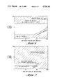
- FIG. 4 is a graphic representation illustrating for the same conditions of FIG. 1 the extent to which the region for satisfactory performance may be increased by utilizing "batch" processing in accordance with the invention.
- FIG. 5 is a graphic representation illustrating the amount of CW or repetitive pulsed laser energy required to remove paint as a function of operating conditions.
- the present invention is not limited to the use of a laser beam of a particular wavelength. Assuming that the necesssary fluence for a particular application can be generated, the laser must provide a laser beam having a wavelength at which the material to be removed is sufficiently opaque to insure effective absorption.
- a typical coat of paint on an aluminum substrate forming part of an airplane will have a coat of primer 0.6-0.9 mil thick and a coat of paint 1.4-2.8 mil thick. Assuming a total thickness of 0.003 inches (75 ⁇ ) and a typical paint ablation energy Q* of approximately 5 KJ/gm (or ⁇ 10KJ/cc), the total laser beam fluence F t required in this case is:
- This fluence or energy in joules/cm 2 can be delivered by a single pulse, a series of pulses, or a CW beam having the effect as if it were pulsed.
- the fluence F a to reach the ablation temperature for paint (about 2 ⁇ 10 3 °K.) is:
- the fluence per pulse F p should be considerably greater than F a or:
- the fluence delivered by the laser beam to the covering material which is intended to be removed must be delivered in a time short compared to that required for heat to diffuse away from the surface of the covering material to prevent excessive heating of the substrate.
- this time t max is: ##EQU1## where ⁇ is the thermal diffusivity in cm 2 /sec of the paint.
- the cross section of the laser beam as it impinges on the surface of the material to be removed is square and that each "spot" must be irradiated three times at one-fifth of the repetition rate of the laser to effect satisfactory removal of the paint or the like to be removed.
- the laser beam is simply caused in conventional manner to sequentially irradiate five portions or "spots".
- the laser beam is caused to return to the first portion (or a point one third the lineal distance of the first portion) and then to move to five consecutive portions.
- FIG. 4 is also similar to FIG. 3 and illustrates the increased size of the operating window by using "batch" processing for a composite skin.
- the use of the "batch" technique in accordance with this invention substantially increases the parameters for removal of paint or the like from a composite substrate as compared to those parameters permitting paint removal where a different technique is used.
- the beam of such a laser is made in conventional manner to sweep over a surface such that substantially each spot is illuminated the number of times necessary to satisfactorily ablate the material to be removed, at a rate that is a fraction of the pulse repetition rate of the laser, and for each time the aforementioned spot is illuminated, a number of consecutive spots substantially the reciprocal of the aforementioned fraction (one of which spots may be the spot being processed) are consecutively illuminated, the material will be satisfactorily ablated in accordance with the invention.
- FIG. 5 is a graphic representation of experimental data using both CW and pulsed laser beams for stripping, in accordance with the invention, paint approximately 0.002 inches thick. These tests were conducted with paint samples according to the aforementioned MIL specification. It may be seen from FIG. 5 that efficient and satisfactory paint removal in accordance with the invention occurs at relatively long pulse lengths as seen by the substrate using a CW laser if the laser flux (fluence per pulse divided by the pulse length) is high enough.
- FIG. 5 there is shown experimental data for removing paint from different substrates (aluminum and fiberglass) for different laser pulse or effective pulse lengths related to fluence per pulse in joules per square centimeter and total fluence [fluence per pulse (F p ) times the number of pulses (N p )] in joules per square centimeter.
- the continuous curved line at the left side of FIG. 5 and the continuous curved line at the right side of FIG. 5 designate approximately the boundary between operating conditions that do not result in satisfactory paint stripping and those conditions that do result in satisfactory paint stripping for different pulse lengths.
- the left-hand continuous line designates approximately the boundary for satisfactory paint stripping for effective pulse lengths of 40, 60 and 120 ⁇ sec pulses.
- the rectangular area delineated at the bottom of the left-hand curved line designates the boundary for pulses of 10-20 ⁇ sec in duration.
- the right-hand continuous line designates approximately the boundary for an effective pulse length of 1.2 msec.
- the small circle and crossed lines is an "error bar" designating approximately the uncertainty of all of the measurements.
- the fluence per pulse (F p ) was approximately 60 joules and the total fluence was also approximately 60 joules, i.e., such a single pulse is effective.
- Effective pulse lengths in accordance with the invention may vary from a minimum of about three microseconds to a maximum of about four thousand microseconds with a total energy applied per square centimeter of not greater than about one hundred joules for each thickness of paint of about 0.003 inches.
Abstract
Description
F.sub.t ˜ρlQ*
F.sub.t ˜75 J/cm.sup.2
F.sub.a ˜LρC.sub.p ΔT
F.sub.a ˜5×10.sup.-4 ×2×1×2×10.sup.3
F.sub.a ˜2 J/cm.sup.2
F.sub.p >>2 J/cm.sup.2
F.sub.p <10.sup.6 t.sub.p
N.sub.p ˜F.sub.t /(F.sub.p -F.sub.a)
N.sub.p ˜75/(10-2)
Claims (2)
Priority Applications (1)
| Application Number | Priority Date | Filing Date | Title |
|---|---|---|---|
| US06/560,672 US4756765A (en) | 1982-01-26 | 1983-12-12 | Laser removal of poor thermally-conductive materials |
Applications Claiming Priority (2)
| Application Number | Priority Date | Filing Date | Title |
|---|---|---|---|
| US34278782A | 1982-01-26 | 1982-01-26 | |
| US06/560,672 US4756765A (en) | 1982-01-26 | 1983-12-12 | Laser removal of poor thermally-conductive materials |
Related Parent Applications (1)
| Application Number | Title | Priority Date | Filing Date |
|---|---|---|---|
| US34278782A Continuation-In-Part | 1982-01-26 | 1982-01-26 |
Related Child Applications (1)
| Application Number | Title | Priority Date | Filing Date |
|---|---|---|---|
| US07/544,616 Reissue USRE33777E (en) | 1982-01-26 | 1990-06-27 | Laser removal of poor thermally-conductive materials |
Publications (1)
| Publication Number | Publication Date |
|---|---|
| US4756765A true US4756765A (en) | 1988-07-12 |
Family
ID=26993199
Family Applications (1)
| Application Number | Title | Priority Date | Filing Date |
|---|---|---|---|
| US06/560,672 Ceased US4756765A (en) | 1982-01-26 | 1983-12-12 | Laser removal of poor thermally-conductive materials |
Country Status (1)
| Country | Link |
|---|---|
| US (1) | US4756765A (en) |
Cited By (87)
| Publication number | Priority date | Publication date | Assignee | Title |
|---|---|---|---|---|
| US4920994A (en) * | 1989-09-12 | 1990-05-01 | The United States Of America As Represented By The United States Department Of Energy | Laser removal of sludge from steam generators |
| FR2641718A1 (en) * | 1989-01-17 | 1990-07-20 | Ardt | METHOD FOR CLEANING THE SURFACE OF SOLID MATERIALS AND DEVICE FOR CARRYING OUT SAID METHOD, USING A SHORT-PULSE IMPULSE POWER LASER, WHICH FOCUSES THE BEAM ON THE SURFACE TO CLEAN |
| EP0391113A2 (en) * | 1989-04-07 | 1990-10-10 | Dornier Luftfahrt Gmbh | Process for removing lacquers from works, especially layered works comprising fibers |
| US5023424A (en) * | 1990-01-22 | 1991-06-11 | Tencor Instruments | Shock wave particle removal method and apparatus |
| US5059764A (en) * | 1988-10-31 | 1991-10-22 | Spectra-Physics, Inc. | Diode-pumped, solid state laser-based workstation for precision materials processing and machining |
| FR2661371A1 (en) * | 1990-04-25 | 1991-10-31 | Aron Rosa Daniele | Method and device for restoring a work of art |
| US5068750A (en) * | 1990-10-22 | 1991-11-26 | Hughes Aircraft Company | Contaminant removal from telescope optical elements |
| US5113582A (en) * | 1990-11-13 | 1992-05-19 | General Electric Company | Method for making a gas turbine engine component |
| US5120395A (en) * | 1990-11-13 | 1992-06-09 | General Electric Company | Method for making a gas turbine engine component with a textured surface |
| US5210944A (en) * | 1990-11-13 | 1993-05-18 | General Electric Company | Method for making a gas turbine engine component |
| US5216808A (en) * | 1990-11-13 | 1993-06-08 | General Electric Company | Method for making or repairing a gas turbine engine component |
| WO1993012942A1 (en) * | 1991-12-24 | 1993-07-08 | Mcdonnell Douglas Corporation | Method and system for removing a coating from a substrate using radiant energy and a particle stream |
| WO1993012906A1 (en) * | 1991-12-24 | 1993-07-08 | Maxwell Laboratories, Inc. | Method and system for control of a material removal process using spectral emission discrimination |
| US5268548A (en) * | 1992-05-08 | 1993-12-07 | The United States Of America As Represented By The Secretary Of The Army | Microwave assisted paint stripping |
| US5292375A (en) * | 1993-06-07 | 1994-03-08 | The United States Of America As Represented By The Secretary Of The Army | Removal of lead based coating by vitrification |
| DE4241575A1 (en) * | 1992-12-10 | 1994-06-16 | Baldwin Gegenheimer Gmbh | Printing roller cleaning - uses laser beam to detach dirt and residue from surface without affecting surface character |
| WO1994023854A1 (en) * | 1993-04-12 | 1994-10-27 | Cauldron Limited Partnership | Removal of surface contaminants by irradiation |
| DE4410613C1 (en) * | 1994-03-26 | 1995-03-30 | Urenco Deutschland Gmbh | Apparatus for removing layers of a surface by means of laser radiation |
| US5419971A (en) * | 1993-03-03 | 1995-05-30 | General Electric Company | Enhanced thermal barrier coating system |
| US5463951A (en) * | 1993-01-20 | 1995-11-07 | Baldwin-Gegenheimer Gmbh | Printing machine spray device |
| US5482561A (en) * | 1993-06-11 | 1996-01-09 | Hughes Aircraft Company | Method for removing organic deposits from sand particles with laser beam |
| US5512123A (en) * | 1992-05-19 | 1996-04-30 | Maxwell Laboratories | Method for using pulsed optical energy to increase the bondability of a surface |
| EP0709145A1 (en) * | 1994-03-10 | 1996-05-01 | Ishikawa, Toshiharu | Film removing device |
| US5571335A (en) * | 1991-12-12 | 1996-11-05 | Cold Jet, Inc. | Method for removal of surface coatings |
| US5613509A (en) * | 1991-12-24 | 1997-03-25 | Maxwell Laboratories, Inc. | Method and apparatus for removing contaminants and coatings from a substrate using pulsed radiant energy and liquid carbon dioxide |
| US5643476A (en) * | 1994-09-21 | 1997-07-01 | University Of Southern California | Laser system for removal of graffiti |
| US5643472A (en) * | 1988-07-08 | 1997-07-01 | Cauldron Limited Partnership | Selective removal of material by irradiation |
| US5679202A (en) * | 1994-03-04 | 1997-10-21 | Smaltirva S.P.A. | Process for removing fluorocarbon resin-based coatings |
| US5782253A (en) * | 1991-12-24 | 1998-07-21 | Mcdonnell Douglas Corporation | System for removing a coating from a substrate |
| US5821175A (en) * | 1988-07-08 | 1998-10-13 | Cauldron Limited Partnership | Removal of surface contaminants by irradiation using various methods to achieve desired inert gas flow over treated surface |
| WO1998046391A1 (en) * | 1997-04-15 | 1998-10-22 | Fraunhofer-Gesellschaft zur Förderung der angewandten Forschung e.V. | Method for removing one or several layers selectively |
| US5864114A (en) * | 1994-03-10 | 1999-01-26 | Toshiharu Ishikawa | Coating removal apparatus using coordinate-controlled laser beam |
| EP0930126A1 (en) * | 1998-01-14 | 1999-07-21 | Fraunhofer-Gesellschaft Zur Förderung Der Angewandten Forschung E.V. | Method of removing superficial layers by means of laser induced shock waves amplified by a cover layer |
| US5951778A (en) * | 1998-09-10 | 1999-09-14 | Adele deCruz | Method for cleaning artwork |
| US5986234A (en) * | 1997-03-28 | 1999-11-16 | The Regents Of The University Of California | High removal rate laser-based coating removal system |
| US6437285B1 (en) | 1998-06-02 | 2002-08-20 | General Lasertronics Corporation | Method and apparatus for treating interior cylindrical surfaces and ablating surface material thereon |
| US6551407B2 (en) | 2001-01-15 | 2003-04-22 | Board Of Trustees Of Michigan State University | Method for treatment of surfaces to remove mold release agents with continuous ultraviolet cleaning light |
| US6565927B1 (en) | 1999-04-07 | 2003-05-20 | Board Of Trustees Of Michigan State University | Method for treatment of surfaces with ultraviolet light |
| US6573474B1 (en) | 2000-10-18 | 2003-06-03 | Chromalloy Gas Turbine Corporation | Process for drilling holes through a thermal barrier coating |
| US20030136505A1 (en) * | 2002-01-18 | 2003-07-24 | Wimmer Phillip L. | Method of preparing a surface for adhesion |
| US20030194506A1 (en) * | 1999-04-07 | 2003-10-16 | Board Of Trustees Of Michigan State University | Chemical functionalization of material surfaces using optical energy and chemicals |
| US20030209859A1 (en) * | 2001-07-05 | 2003-11-13 | Young Lionel A. | Seal ring and method of forming micro-topography ring surfaces with a laser |
| US6649225B2 (en) | 1999-04-07 | 2003-11-18 | Board Of Trustees Of Michigan State University | Process for the treatment of a fiber |
| US6676762B2 (en) | 2001-01-15 | 2004-01-13 | Board Of Trustees Of Michigan State University | Method for cleaning a finished and polished surface of a metal automotive wheel |
| US20040219290A1 (en) * | 2003-04-30 | 2004-11-04 | Nagaraj Bangalore Aswatha | Method for applying or repairing thermal barrier coatings |
| US20040224618A1 (en) * | 2000-09-08 | 2004-11-11 | Rivir Michael E. | Particle blast apparatus |
| US20050087529A1 (en) * | 2003-10-24 | 2005-04-28 | Gallivan James R. | Selective layer millimeter-wave surface-heating system and method |
| US20050150878A1 (en) * | 2004-01-09 | 2005-07-14 | General Lasertronics Corporation | Color sensing for laser decoating |
| US20050247894A1 (en) * | 2004-05-05 | 2005-11-10 | Watkins Charles M | Systems and methods for forming apertures in microfeature workpieces |
| WO2005108376A1 (en) * | 2004-05-06 | 2005-11-17 | Smithkline Beecham Corporation | Calcilytic compounds |
| EP1598121A2 (en) * | 2004-05-18 | 2005-11-23 | Airbus Deutschland GmbH | Laser-based stripping method |
| WO2005111728A2 (en) * | 2004-05-10 | 2005-11-24 | Matsushita Electric Industrial Co., Ltd. | Composite sheet material selection method for use in ultra-fast laser patterning |
| US20060240687A1 (en) * | 2004-08-27 | 2006-10-26 | Micron Technology, Inc. | Slanted vias for electrical circuits on circuit boards and other substrates |
| US20060289968A1 (en) * | 2005-06-28 | 2006-12-28 | Micron Technology, Inc. | Conductive interconnect structures and formation methods using supercritical fluids |
| US20070049016A1 (en) * | 2005-09-01 | 2007-03-01 | Micron Technology, Inc. | Microfeature workpieces and methods for forming interconnects in microfeature workpieces |
| US20070045120A1 (en) * | 2005-09-01 | 2007-03-01 | Micron Technology, Inc. | Methods and apparatus for filling features in microfeature workpieces |
| US20070209682A1 (en) * | 2006-03-08 | 2007-09-13 | Stmicroelectronics S.A. | Cleaning of photolithography masks |
| US20070267754A1 (en) * | 2005-09-01 | 2007-11-22 | Micron Technology, Inc. | Microfeature workpieces and methods for forming interconnects in microfeature workpieces |
| US20070281473A1 (en) * | 2006-06-01 | 2007-12-06 | Micron Technology, Inc. | Microelectronic workpieces and methods and systems for forming interconnects in microelectronic workpieces |
| US20080054444A1 (en) * | 2006-08-31 | 2008-03-06 | Micron Technology, Inc. | Microfeature workpieces having interconnects and conductive backplanes, and associated systems and methods |
| US20080111213A1 (en) * | 2004-09-02 | 2008-05-15 | Micron Technology, Inc. | Through-wafer interconnects for photoimager and memory wafers |
| US7413979B2 (en) | 2003-11-13 | 2008-08-19 | Micron Technology, Inc. | Methods for forming vias in microelectronic devices, and methods for packaging microelectronic devices |
| US7425499B2 (en) | 2004-08-24 | 2008-09-16 | Micron Technology, Inc. | Methods for forming interconnects in vias and microelectronic workpieces including such interconnects |
| US20090008827A1 (en) * | 2007-07-05 | 2009-01-08 | General Lasertronics Corporation, A Corporation Of The State Of California | Aperture adapters for laser-based coating removal end-effector |
| US20090007933A1 (en) * | 2007-03-22 | 2009-01-08 | Thomas James W | Methods for stripping and modifying surfaces with laser-induced ablation |
| US20090008780A1 (en) * | 2004-12-30 | 2009-01-08 | Micron Technology, Inc. | Methods for forming interconnects in microelectronic workpieces and microelectronic workpieces formed using such methods |
| US20090057912A1 (en) * | 2007-08-31 | 2009-03-05 | Micron Technology, Inc. | Partitioned through-layer via and associated systems and methods |
| US7531453B2 (en) | 2004-06-29 | 2009-05-12 | Micron Technology, Inc. | Microelectronic devices and methods for forming interconnects in microelectronic devices |
| US20090146312A1 (en) * | 2007-12-06 | 2009-06-11 | Micron Technology, Inc. | Methods for forming interconnects in microelectronic workpieces and microelectronic workpieces formed using such methods |
| US20090224178A1 (en) * | 2005-06-20 | 2009-09-10 | Francois Champonnois | Method and device for laser ablation of a surface coating from a wall, such as a coat of paint in a nuclear plant |
| US7622377B2 (en) | 2005-09-01 | 2009-11-24 | Micron Technology, Inc. | Microfeature workpiece substrates having through-substrate vias, and associated methods of formation |
| US7629249B2 (en) | 2006-08-28 | 2009-12-08 | Micron Technology, Inc. | Microfeature workpieces having conductive interconnect structures formed by chemically reactive processes, and associated systems and methods |
| US20100000977A1 (en) * | 2008-07-07 | 2010-01-07 | Ashok Sudhakar | Method for removal of content-based stripe and the like on a substrate and equipment thereof |
| US7800014B2 (en) | 2004-01-09 | 2010-09-21 | General Lasertronics Corporation | Color sensing for laser decoating |
| US8084866B2 (en) | 2003-12-10 | 2011-12-27 | Micron Technology, Inc. | Microelectronic devices and methods for filling vias in microelectronic devices |
| WO2012010125A3 (en) * | 2010-06-23 | 2012-04-12 | Eads Deutschland Gmbh | Method, device, and arrangement for removing organic soiling from incident-flow areas |
| US8624151B2 (en) | 2011-07-19 | 2014-01-07 | Pratt & Whitney Canada Corp. | Laser drilling methods of shallow-angled holes |
| US8631557B2 (en) | 2011-07-19 | 2014-01-21 | Pratt & Whitney Canada Corp. | Laser drilling methods of shallow-angled holes |
| CN104438230A (en) * | 2014-11-17 | 2015-03-25 | 成都莱普科技有限公司 | Industrial product laser cleaning system and control method thereof |
| US9434025B2 (en) | 2011-07-19 | 2016-09-06 | Pratt & Whitney Canada Corp. | Laser drilling methods of shallow-angled holes |
| US9868179B2 (en) | 2012-03-09 | 2018-01-16 | TOYOKOH, Co., Ltd. | Laser irradiation device, laser irradiation system, and method for removing coating or adhering matter |
| RU2668619C1 (en) * | 2017-08-14 | 2018-10-02 | Публичное акционерное общество "Челябинский трубопрокатный завод" (ПАО "ЧТПЗ") | Method of laser surface cleaning |
| US10112257B1 (en) | 2010-07-09 | 2018-10-30 | General Lasertronics Corporation | Coating ablating apparatus with coating removal detection |
| WO2019002847A1 (en) * | 2017-06-26 | 2019-01-03 | Andritz Powerlase Ltd | Method of removing a coating with pulsed laser, computer readable medium and laser |
| US10610963B2 (en) | 2017-05-17 | 2020-04-07 | General Electric Company | Surface treatment of turbomachinery |
| CN111687143A (en) * | 2020-05-20 | 2020-09-22 | 中国民用航空飞行学院 | Real-time monitoring control method and system for laser layered paint removal of aircraft skin |
| CN114985939A (en) * | 2022-05-20 | 2022-09-02 | 南京航空航天大学 | Method for removing paint on surface of carbon fiber reinforced resin matrix composite material containing conductive layer |
Citations (3)
| Publication number | Priority date | Publication date | Assignee | Title |
|---|---|---|---|---|
| US3503804A (en) * | 1967-04-25 | 1970-03-31 | Hellmut Schneider | Method and apparatus for the production of sonic or ultrasonic waves on a surface |
| US4063063A (en) * | 1975-02-14 | 1977-12-13 | Acieries Reunies De Burbach-Eich-Dudelange S.A. Arbed | Method of descaling metal products |
| US4368080A (en) * | 1979-10-25 | 1983-01-11 | Robert Langen | Method of removing rust from metallic objects |
-
1983
- 1983-12-12 US US06/560,672 patent/US4756765A/en not_active Ceased
Patent Citations (3)
| Publication number | Priority date | Publication date | Assignee | Title |
|---|---|---|---|---|
| US3503804A (en) * | 1967-04-25 | 1970-03-31 | Hellmut Schneider | Method and apparatus for the production of sonic or ultrasonic waves on a surface |
| US4063063A (en) * | 1975-02-14 | 1977-12-13 | Acieries Reunies De Burbach-Eich-Dudelange S.A. Arbed | Method of descaling metal products |
| US4368080A (en) * | 1979-10-25 | 1983-01-11 | Robert Langen | Method of removing rust from metallic objects |
Non-Patent Citations (9)
| Title |
|---|
| Aviation Week and Space Tech., "Protection Against High-Energy Lasers Found", (Jun. 16, 1980), p. 232. |
| Aviation Week and Space Tech., (Jan. 29, 1979), p. 55. * |
| Aviation Week and Space Tech., Protection Against High Energy Lasers Found , (Jun. 16, 1980), p. 232. * |
| Electronics, "Lasers Strip Wire Insulation", vol. 49, No. 19, (Sep. 16, 1976), pp. 50, 52. |
| Electronics, Lasers Strip Wire Insulation , vol. 49, No. 19, (Sep. 16, 1976), pp. 50, 52. * |
| Hawkins et al., "Laser Removal of Polymer Coating", IBM Tech. Discl. Bull., vol. 12, No. 6, Nov. 1969, p. 735. |
| Hawkins et al., Laser Removal of Polymer Coating , IBM Tech. Discl. Bull., vol. 12, No. 6, Nov. 1969, p. 735. * |
| Lowndes, "Metallic Composite Coating Yields Gains", Aviation Week and Space Tech., (Nov. 24, 1980), p. 58. |
| Lowndes, Metallic Composite Coating Yields Gains , Aviation Week and Space Tech., (Nov. 24, 1980), p. 58. * |
Cited By (162)
| Publication number | Priority date | Publication date | Assignee | Title |
|---|---|---|---|---|
| US5821175A (en) * | 1988-07-08 | 1998-10-13 | Cauldron Limited Partnership | Removal of surface contaminants by irradiation using various methods to achieve desired inert gas flow over treated surface |
| US5643472A (en) * | 1988-07-08 | 1997-07-01 | Cauldron Limited Partnership | Selective removal of material by irradiation |
| US5059764A (en) * | 1988-10-31 | 1991-10-22 | Spectra-Physics, Inc. | Diode-pumped, solid state laser-based workstation for precision materials processing and machining |
| FR2641718A1 (en) * | 1989-01-17 | 1990-07-20 | Ardt | METHOD FOR CLEANING THE SURFACE OF SOLID MATERIALS AND DEVICE FOR CARRYING OUT SAID METHOD, USING A SHORT-PULSE IMPULSE POWER LASER, WHICH FOCUSES THE BEAM ON THE SURFACE TO CLEAN |
| WO1990007988A1 (en) * | 1989-01-17 | 1990-07-26 | Agence Regionale De Developpements Technologiques | Method for cleaning a surface with a laser |
| EP0380387A1 (en) * | 1989-01-17 | 1990-08-01 | Agence Regionale De Developpements Technologiques - Ardt - | Surface cleaning with a laser |
| US5151134A (en) * | 1989-01-17 | 1992-09-29 | Agence Regionale De Developpements Technologiques | Method and a device for cleaning a surface with a laser |
| EP0391113A2 (en) * | 1989-04-07 | 1990-10-10 | Dornier Luftfahrt Gmbh | Process for removing lacquers from works, especially layered works comprising fibers |
| EP0391113A3 (en) * | 1989-04-07 | 1991-07-10 | Dornier Luftfahrt Gmbh | Process for removing lacquers from works, especially layered works comprising fibers |
| US4920994A (en) * | 1989-09-12 | 1990-05-01 | The United States Of America As Represented By The United States Department Of Energy | Laser removal of sludge from steam generators |
| US5023424A (en) * | 1990-01-22 | 1991-06-11 | Tencor Instruments | Shock wave particle removal method and apparatus |
| FR2661371A1 (en) * | 1990-04-25 | 1991-10-31 | Aron Rosa Daniele | Method and device for restoring a work of art |
| US5068750A (en) * | 1990-10-22 | 1991-11-26 | Hughes Aircraft Company | Contaminant removal from telescope optical elements |
| US5113582A (en) * | 1990-11-13 | 1992-05-19 | General Electric Company | Method for making a gas turbine engine component |
| US5120395A (en) * | 1990-11-13 | 1992-06-09 | General Electric Company | Method for making a gas turbine engine component with a textured surface |
| US5210944A (en) * | 1990-11-13 | 1993-05-18 | General Electric Company | Method for making a gas turbine engine component |
| US5216808A (en) * | 1990-11-13 | 1993-06-08 | General Electric Company | Method for making or repairing a gas turbine engine component |
| US5571335A (en) * | 1991-12-12 | 1996-11-05 | Cold Jet, Inc. | Method for removal of surface coatings |
| WO1993012906A1 (en) * | 1991-12-24 | 1993-07-08 | Maxwell Laboratories, Inc. | Method and system for control of a material removal process using spectral emission discrimination |
| US5613509A (en) * | 1991-12-24 | 1997-03-25 | Maxwell Laboratories, Inc. | Method and apparatus for removing contaminants and coatings from a substrate using pulsed radiant energy and liquid carbon dioxide |
| WO1993012942A1 (en) * | 1991-12-24 | 1993-07-08 | Mcdonnell Douglas Corporation | Method and system for removing a coating from a substrate using radiant energy and a particle stream |
| US5782253A (en) * | 1991-12-24 | 1998-07-21 | Mcdonnell Douglas Corporation | System for removing a coating from a substrate |
| US5268548A (en) * | 1992-05-08 | 1993-12-07 | The United States Of America As Represented By The Secretary Of The Army | Microwave assisted paint stripping |
| US5512123A (en) * | 1992-05-19 | 1996-04-30 | Maxwell Laboratories | Method for using pulsed optical energy to increase the bondability of a surface |
| US5592879A (en) * | 1992-12-10 | 1997-01-14 | Baldwin-Gegenheimer Gmbh | Method and apparatus for the contact-free removal of dirt from the cylinders of printing machines |
| DE4241575A1 (en) * | 1992-12-10 | 1994-06-16 | Baldwin Gegenheimer Gmbh | Printing roller cleaning - uses laser beam to detach dirt and residue from surface without affecting surface character |
| US5463951A (en) * | 1993-01-20 | 1995-11-07 | Baldwin-Gegenheimer Gmbh | Printing machine spray device |
| US5419971A (en) * | 1993-03-03 | 1995-05-30 | General Electric Company | Enhanced thermal barrier coating system |
| US6503574B1 (en) | 1993-03-03 | 2003-01-07 | General Electric Co. | Method for producing an enhanced thermal barrier coating system |
| WO1994023854A1 (en) * | 1993-04-12 | 1994-10-27 | Cauldron Limited Partnership | Removal of surface contaminants by irradiation |
| US5292375A (en) * | 1993-06-07 | 1994-03-08 | The United States Of America As Represented By The Secretary Of The Army | Removal of lead based coating by vitrification |
| US5482561A (en) * | 1993-06-11 | 1996-01-09 | Hughes Aircraft Company | Method for removing organic deposits from sand particles with laser beam |
| US5679202A (en) * | 1994-03-04 | 1997-10-21 | Smaltirva S.P.A. | Process for removing fluorocarbon resin-based coatings |
| EP0709145A4 (en) * | 1994-03-10 | 1996-10-02 | Ishikawa Toshiharu | Film removing device |
| EP0709145A1 (en) * | 1994-03-10 | 1996-05-01 | Ishikawa, Toshiharu | Film removing device |
| US5864114A (en) * | 1994-03-10 | 1999-01-26 | Toshiharu Ishikawa | Coating removal apparatus using coordinate-controlled laser beam |
| DE4410613C1 (en) * | 1994-03-26 | 1995-03-30 | Urenco Deutschland Gmbh | Apparatus for removing layers of a surface by means of laser radiation |
| US5681395A (en) * | 1994-03-26 | 1997-10-28 | Urenco Deutschland Gmbh | Method for the removal of a surface layer by a laser beam |
| WO1995026255A1 (en) * | 1994-03-26 | 1995-10-05 | Urenco Deutschland Gmbh | Device for removing layers from a surface using laser radiation |
| US5643476A (en) * | 1994-09-21 | 1997-07-01 | University Of Southern California | Laser system for removal of graffiti |
| US5986234A (en) * | 1997-03-28 | 1999-11-16 | The Regents Of The University Of California | High removal rate laser-based coating removal system |
| WO1998046391A1 (en) * | 1997-04-15 | 1998-10-22 | Fraunhofer-Gesellschaft zur Förderung der angewandten Forschung e.V. | Method for removing one or several layers selectively |
| EP0930126A1 (en) * | 1998-01-14 | 1999-07-21 | Fraunhofer-Gesellschaft Zur Förderung Der Angewandten Forschung E.V. | Method of removing superficial layers by means of laser induced shock waves amplified by a cover layer |
| US6437285B1 (en) | 1998-06-02 | 2002-08-20 | General Lasertronics Corporation | Method and apparatus for treating interior cylindrical surfaces and ablating surface material thereon |
| US5951778A (en) * | 1998-09-10 | 1999-09-14 | Adele deCruz | Method for cleaning artwork |
| US20030194506A1 (en) * | 1999-04-07 | 2003-10-16 | Board Of Trustees Of Michigan State University | Chemical functionalization of material surfaces using optical energy and chemicals |
| US7094451B2 (en) | 1999-04-07 | 2006-08-22 | Board Of Trustees Of Michigan State University | Chemical functionalization of material surfaces using optical energy and chemicals |
| US6649225B2 (en) | 1999-04-07 | 2003-11-18 | Board Of Trustees Of Michigan State University | Process for the treatment of a fiber |
| US6648973B2 (en) | 1999-04-07 | 2003-11-18 | Board Of Trustees Of Michigan State University | Process for the treatment of a fiber |
| US6565927B1 (en) | 1999-04-07 | 2003-05-20 | Board Of Trustees Of Michigan State University | Method for treatment of surfaces with ultraviolet light |
| US20040224618A1 (en) * | 2000-09-08 | 2004-11-11 | Rivir Michael E. | Particle blast apparatus |
| US7950984B2 (en) | 2000-09-08 | 2011-05-31 | Cold Jet, Inc. | Particle blast apparatus |
| US6573474B1 (en) | 2000-10-18 | 2003-06-03 | Chromalloy Gas Turbine Corporation | Process for drilling holes through a thermal barrier coating |
| US6551407B2 (en) | 2001-01-15 | 2003-04-22 | Board Of Trustees Of Michigan State University | Method for treatment of surfaces to remove mold release agents with continuous ultraviolet cleaning light |
| US6676762B2 (en) | 2001-01-15 | 2004-01-13 | Board Of Trustees Of Michigan State University | Method for cleaning a finished and polished surface of a metal automotive wheel |
| US7194803B2 (en) | 2001-07-05 | 2007-03-27 | Flowserve Management Company | Seal ring and method of forming micro-topography ring surfaces with a laser |
| US20030209859A1 (en) * | 2001-07-05 | 2003-11-13 | Young Lionel A. | Seal ring and method of forming micro-topography ring surfaces with a laser |
| US20030136505A1 (en) * | 2002-01-18 | 2003-07-24 | Wimmer Phillip L. | Method of preparing a surface for adhesion |
| US20040219290A1 (en) * | 2003-04-30 | 2004-11-04 | Nagaraj Bangalore Aswatha | Method for applying or repairing thermal barrier coatings |
| US7094450B2 (en) | 2003-04-30 | 2006-08-22 | General Electric Company | Method for applying or repairing thermal barrier coatings |
| US20050087529A1 (en) * | 2003-10-24 | 2005-04-28 | Gallivan James R. | Selective layer millimeter-wave surface-heating system and method |
| US7498549B2 (en) | 2003-10-24 | 2009-03-03 | Raytheon Company | Selective layer millimeter-wave surface-heating system and method |
| US9653420B2 (en) | 2003-11-13 | 2017-05-16 | Micron Technology, Inc. | Microelectronic devices and methods for filling vias in microelectronic devices |
| US7759800B2 (en) | 2003-11-13 | 2010-07-20 | Micron Technology, Inc. | Microelectronics devices, having vias, and packaged microelectronic devices having vias |
| US7413979B2 (en) | 2003-11-13 | 2008-08-19 | Micron Technology, Inc. | Methods for forming vias in microelectronic devices, and methods for packaging microelectronic devices |
| US11177175B2 (en) | 2003-12-10 | 2021-11-16 | Micron Technology, Inc. | Microelectronic devices and methods for filling vias in microelectronic devices |
| US8748311B2 (en) | 2003-12-10 | 2014-06-10 | Micron Technology, Inc. | Microelectronic devices and methods for filing vias in microelectronic devices |
| US8084866B2 (en) | 2003-12-10 | 2011-12-27 | Micron Technology, Inc. | Microelectronic devices and methods for filling vias in microelectronic devices |
| US8030594B2 (en) | 2004-01-09 | 2011-10-04 | General Lasertronics Corporation | Color sensing for laser decoating |
| US8269135B2 (en) | 2004-01-09 | 2012-09-18 | General Lasertronics Corporation | Color sensing for laser decoating |
| US20100044357A1 (en) * | 2004-01-09 | 2010-02-25 | General Lasertronics Corporation | Color sensing for laser decoating |
| US9375807B2 (en) | 2004-01-09 | 2016-06-28 | General Lasertronics Corporation | Color sensing for laser decoating |
| US7633033B2 (en) | 2004-01-09 | 2009-12-15 | General Lasertronics Corporation | Color sensing for laser decoating |
| US7800014B2 (en) | 2004-01-09 | 2010-09-21 | General Lasertronics Corporation | Color sensing for laser decoating |
| US20050150878A1 (en) * | 2004-01-09 | 2005-07-14 | General Lasertronics Corporation | Color sensing for laser decoating |
| US8664562B2 (en) | 2004-05-05 | 2014-03-04 | Micron Technology, Inc. | Systems and methods for forming apertures in microfeature workpieces |
| US20060191882A1 (en) * | 2004-05-05 | 2006-08-31 | Micron Technology, Inc. | Systems and methods for forming apertures in microfeature workpieces |
| US20060186097A1 (en) * | 2004-05-05 | 2006-08-24 | Micron Technology, Inc. | Systems and methods for forming apertures in microfeature workpieces |
| US9452492B2 (en) | 2004-05-05 | 2016-09-27 | Micron Technology, Inc. | Systems and methods for forming apertures in microfeature workpieces |
| US20050247894A1 (en) * | 2004-05-05 | 2005-11-10 | Watkins Charles M | Systems and methods for forming apertures in microfeature workpieces |
| US8536485B2 (en) | 2004-05-05 | 2013-09-17 | Micron Technology, Inc. | Systems and methods for forming apertures in microfeature workpieces |
| US10010977B2 (en) | 2004-05-05 | 2018-07-03 | Micron Technology, Inc. | Systems and methods for forming apertures in microfeature workpieces |
| US8686313B2 (en) | 2004-05-05 | 2014-04-01 | Micron Technology, Inc. | System and methods for forming apertures in microfeature workpieces |
| WO2005108376A1 (en) * | 2004-05-06 | 2005-11-17 | Smithkline Beecham Corporation | Calcilytic compounds |
| US7773216B2 (en) | 2004-05-10 | 2010-08-10 | Panasonic Corporation | Composite sheet material selection method for use in ultra-fast laser patterning |
| US20080291451A1 (en) * | 2004-05-10 | 2008-11-27 | Matsushita Electric Industrial Co., Ltd | Composite Sheet Material Selection Method for Use in Ultra-Fast Laser Patterning |
| WO2005111728A2 (en) * | 2004-05-10 | 2005-11-24 | Matsushita Electric Industrial Co., Ltd. | Composite sheet material selection method for use in ultra-fast laser patterning |
| WO2005111728A3 (en) * | 2004-05-10 | 2006-05-18 | Matsushita Electric Ind Co Ltd | Composite sheet material selection method for use in ultra-fast laser patterning |
| JP4842927B2 (en) * | 2004-05-10 | 2011-12-21 | パナソニック株式会社 | Composite sheet material selection method for ultrafast laser patterning |
| EP1598121A2 (en) * | 2004-05-18 | 2005-11-23 | Airbus Deutschland GmbH | Laser-based stripping method |
| US7531453B2 (en) | 2004-06-29 | 2009-05-12 | Micron Technology, Inc. | Microelectronic devices and methods for forming interconnects in microelectronic devices |
| US7829976B2 (en) | 2004-06-29 | 2010-11-09 | Micron Technology, Inc. | Microelectronic devices and methods for forming interconnects in microelectronic devices |
| US7425499B2 (en) | 2004-08-24 | 2008-09-16 | Micron Technology, Inc. | Methods for forming interconnects in vias and microelectronic workpieces including such interconnects |
| US7435913B2 (en) | 2004-08-27 | 2008-10-14 | Micron Technology, Inc. | Slanted vias for electrical circuits on circuit boards and other substrates |
| US8322031B2 (en) | 2004-08-27 | 2012-12-04 | Micron Technology, Inc. | Method of manufacturing an interposer |
| US20060240687A1 (en) * | 2004-08-27 | 2006-10-26 | Micron Technology, Inc. | Slanted vias for electrical circuits on circuit boards and other substrates |
| US7683458B2 (en) | 2004-09-02 | 2010-03-23 | Micron Technology, Inc. | Through-wafer interconnects for photoimager and memory wafers |
| US20100171217A1 (en) * | 2004-09-02 | 2010-07-08 | Micron Technology, Inc. | Through-wafer interconnects for photoimager and memory wafers |
| US7956443B2 (en) | 2004-09-02 | 2011-06-07 | Micron Technology, Inc. | Through-wafer interconnects for photoimager and memory wafers |
| US20080111213A1 (en) * | 2004-09-02 | 2008-05-15 | Micron Technology, Inc. | Through-wafer interconnects for photoimager and memory wafers |
| US8502353B2 (en) | 2004-09-02 | 2013-08-06 | Micron Technology, Inc. | Through-wafer interconnects for photoimager and memory wafers |
| US8669179B2 (en) | 2004-09-02 | 2014-03-11 | Micron Technology, Inc. | Through-wafer interconnects for photoimager and memory wafers |
| US20110233777A1 (en) * | 2004-09-02 | 2011-09-29 | Micron Technology, Inc. | Through-wafer interconnects for photoimager and memory wafers |
| US20090008780A1 (en) * | 2004-12-30 | 2009-01-08 | Micron Technology, Inc. | Methods for forming interconnects in microelectronic workpieces and microelectronic workpieces formed using such methods |
| US9214391B2 (en) | 2004-12-30 | 2015-12-15 | Micron Technology, Inc. | Methods for forming interconnects in microelectronic workpieces and microelectronic workpieces formed using such methods |
| US7589008B2 (en) | 2004-12-30 | 2009-09-15 | Micron Technology, Inc. | Methods for forming interconnects in microelectronic workpieces and microelectronic workpieces formed using such methods |
| US8330073B2 (en) * | 2005-06-20 | 2012-12-11 | Commissariat A L'energie Atomique | Method and device for laser ablation of a surface coating from a wall, such as a coat of paint in a nuclear plant |
| US20090224178A1 (en) * | 2005-06-20 | 2009-09-10 | Francois Champonnois | Method and device for laser ablation of a surface coating from a wall, such as a coat of paint in a nuclear plant |
| US20060289968A1 (en) * | 2005-06-28 | 2006-12-28 | Micron Technology, Inc. | Conductive interconnect structures and formation methods using supercritical fluids |
| US8008192B2 (en) | 2005-06-28 | 2011-08-30 | Micron Technology, Inc. | Conductive interconnect structures and formation methods using supercritical fluids |
| US7795134B2 (en) | 2005-06-28 | 2010-09-14 | Micron Technology, Inc. | Conductive interconnect structures and formation methods using supercritical fluids |
| US9293367B2 (en) | 2005-06-28 | 2016-03-22 | Micron Technology, Inc. | Conductive interconnect structures and formation methods using supercritical fluids |
| US7915736B2 (en) | 2005-09-01 | 2011-03-29 | Micron Technology, Inc. | Microfeature workpieces and methods for forming interconnects in microfeature workpieces |
| US11476160B2 (en) | 2005-09-01 | 2022-10-18 | Micron Technology, Inc. | Microfeature workpieces and methods for forming interconnects in microfeature workpieces |
| US20110079900A1 (en) * | 2005-09-01 | 2011-04-07 | Micron Technology, Inc. | Microfeature workpieces and methods for forming interconnects in microfeature workpieces |
| US7863187B2 (en) | 2005-09-01 | 2011-01-04 | Micron Technology, Inc. | Microfeature workpieces and methods for forming interconnects in microfeature workpieces |
| US20070267754A1 (en) * | 2005-09-01 | 2007-11-22 | Micron Technology, Inc. | Microfeature workpieces and methods for forming interconnects in microfeature workpieces |
| US7622377B2 (en) | 2005-09-01 | 2009-11-24 | Micron Technology, Inc. | Microfeature workpiece substrates having through-substrate vias, and associated methods of formation |
| US20070049016A1 (en) * | 2005-09-01 | 2007-03-01 | Micron Technology, Inc. | Microfeature workpieces and methods for forming interconnects in microfeature workpieces |
| US20070045120A1 (en) * | 2005-09-01 | 2007-03-01 | Micron Technology, Inc. | Methods and apparatus for filling features in microfeature workpieces |
| US7927969B2 (en) * | 2006-03-08 | 2011-04-19 | Stmicroelectronics S.A. | Cleaning of photolithography masks |
| US20070209682A1 (en) * | 2006-03-08 | 2007-09-13 | Stmicroelectronics S.A. | Cleaning of photolithography masks |
| US20070281473A1 (en) * | 2006-06-01 | 2007-12-06 | Micron Technology, Inc. | Microelectronic workpieces and methods and systems for forming interconnects in microelectronic workpieces |
| US7749899B2 (en) | 2006-06-01 | 2010-07-06 | Micron Technology, Inc. | Microelectronic workpieces and methods and systems for forming interconnects in microelectronic workpieces |
| US7629249B2 (en) | 2006-08-28 | 2009-12-08 | Micron Technology, Inc. | Microfeature workpieces having conductive interconnect structures formed by chemically reactive processes, and associated systems and methods |
| US20100065970A1 (en) * | 2006-08-28 | 2010-03-18 | Micron Technology, Inc. | Microfeature workpieces having conductive interconnect structures formed by chemically reactive processes, and associated systems and methods |
| US7973411B2 (en) | 2006-08-28 | 2011-07-05 | Micron Technology, Inc. | Microfeature workpieces having conductive interconnect structures formed by chemically reactive processes, and associated systems and methods |
| US8610279B2 (en) | 2006-08-28 | 2013-12-17 | Micron Technologies, Inc. | Microfeature workpieces having conductive interconnect structures formed by chemically reactive processes, and associated systems and methods |
| US20080054444A1 (en) * | 2006-08-31 | 2008-03-06 | Micron Technology, Inc. | Microfeature workpieces having interconnects and conductive backplanes, and associated systems and methods |
| US9570350B2 (en) | 2006-08-31 | 2017-02-14 | Micron Technology, Inc. | Microfeature workpieces having interconnects and conductive backplanes, and associated systems and methods |
| US9099539B2 (en) | 2006-08-31 | 2015-08-04 | Micron Technology, Inc. | Microfeature workpieces having interconnects and conductive backplanes, and associated systems and methods |
| US7902643B2 (en) | 2006-08-31 | 2011-03-08 | Micron Technology, Inc. | Microfeature workpieces having interconnects and conductive backplanes, and associated systems and methods |
| US20110151621A1 (en) * | 2006-08-31 | 2011-06-23 | Micron Technology, Inc. | Microfeature workpieces having interconnects and conductive backplanes, and associated systems and methods |
| US8536483B2 (en) * | 2007-03-22 | 2013-09-17 | General Lasertronics Corporation | Methods for stripping and modifying surfaces with laser-induced ablation |
| US20090007933A1 (en) * | 2007-03-22 | 2009-01-08 | Thomas James W | Methods for stripping and modifying surfaces with laser-induced ablation |
| US20090008827A1 (en) * | 2007-07-05 | 2009-01-08 | General Lasertronics Corporation, A Corporation Of The State Of California | Aperture adapters for laser-based coating removal end-effector |
| US8367538B2 (en) | 2007-08-31 | 2013-02-05 | Micron Technology, Inc. | Partitioned through-layer via and associated systems and methods |
| US20110019372A1 (en) * | 2007-08-31 | 2011-01-27 | Micron Technology, Inc. | Partitioned through-layer via and associated systems and methods |
| US8536046B2 (en) | 2007-08-31 | 2013-09-17 | Micron Technology | Partitioned through-layer via and associated systems and methods |
| US7830018B2 (en) | 2007-08-31 | 2010-11-09 | Micron Technology, Inc. | Partitioned through-layer via and associated systems and methods |
| US20090057912A1 (en) * | 2007-08-31 | 2009-03-05 | Micron Technology, Inc. | Partitioned through-layer via and associated systems and methods |
| US7884015B2 (en) | 2007-12-06 | 2011-02-08 | Micron Technology, Inc. | Methods for forming interconnects in microelectronic workpieces and microelectronic workpieces formed using such methods |
| US8247907B2 (en) | 2007-12-06 | 2012-08-21 | Micron Technology, Inc. | Methods for forming interconnects in microelectronic workpieces and microelectronic workpieces formed using such methods |
| US9281241B2 (en) | 2007-12-06 | 2016-03-08 | Micron Technology, Inc. | Methods for forming interconnects in microelectronic workpieces and microelectronic workpieces formed using such methods |
| US20110133302A1 (en) * | 2007-12-06 | 2011-06-09 | Micron Technology, Inc. | Methods for forming interconnects in microelectronic workpieces and microelectronic workpieces formed using such methods |
| US20090146312A1 (en) * | 2007-12-06 | 2009-06-11 | Micron Technology, Inc. | Methods for forming interconnects in microelectronic workpieces and microelectronic workpieces formed using such methods |
| US20100000977A1 (en) * | 2008-07-07 | 2010-01-07 | Ashok Sudhakar | Method for removal of content-based stripe and the like on a substrate and equipment thereof |
| WO2012010125A3 (en) * | 2010-06-23 | 2012-04-12 | Eads Deutschland Gmbh | Method, device, and arrangement for removing organic soiling from incident-flow areas |
| US10112257B1 (en) | 2010-07-09 | 2018-10-30 | General Lasertronics Corporation | Coating ablating apparatus with coating removal detection |
| US9434025B2 (en) | 2011-07-19 | 2016-09-06 | Pratt & Whitney Canada Corp. | Laser drilling methods of shallow-angled holes |
| US8624151B2 (en) | 2011-07-19 | 2014-01-07 | Pratt & Whitney Canada Corp. | Laser drilling methods of shallow-angled holes |
| US8631557B2 (en) | 2011-07-19 | 2014-01-21 | Pratt & Whitney Canada Corp. | Laser drilling methods of shallow-angled holes |
| US11135681B2 (en) | 2012-03-09 | 2021-10-05 | TOYOKOH, Co., Ltd. | Laser irradiation device, laser irradiation system, and method for removing coating or adhering matter |
| US9868179B2 (en) | 2012-03-09 | 2018-01-16 | TOYOKOH, Co., Ltd. | Laser irradiation device, laser irradiation system, and method for removing coating or adhering matter |
| CN104438230A (en) * | 2014-11-17 | 2015-03-25 | 成都莱普科技有限公司 | Industrial product laser cleaning system and control method thereof |
| US10610963B2 (en) | 2017-05-17 | 2020-04-07 | General Electric Company | Surface treatment of turbomachinery |
| WO2019002847A1 (en) * | 2017-06-26 | 2019-01-03 | Andritz Powerlase Ltd | Method of removing a coating with pulsed laser, computer readable medium and laser |
| RU2668619C1 (en) * | 2017-08-14 | 2018-10-02 | Публичное акционерное общество "Челябинский трубопрокатный завод" (ПАО "ЧТПЗ") | Method of laser surface cleaning |
| CN111687143A (en) * | 2020-05-20 | 2020-09-22 | 中国民用航空飞行学院 | Real-time monitoring control method and system for laser layered paint removal of aircraft skin |
| CN111687143B (en) * | 2020-05-20 | 2021-09-24 | 中国民用航空飞行学院 | Real-time monitoring control method and system for laser layered paint removal of aircraft skin |
| CN114985939A (en) * | 2022-05-20 | 2022-09-02 | 南京航空航天大学 | Method for removing paint on surface of carbon fiber reinforced resin matrix composite material containing conductive layer |
| CN114985939B (en) * | 2022-05-20 | 2023-08-18 | 南京航空航天大学 | Surface paint removal method for carbon fiber reinforced resin matrix composite material containing conductive layer |
Similar Documents
| Publication | Publication Date | Title |
|---|---|---|
| US4756765A (en) | Laser removal of poor thermally-conductive materials | |
| USRE33777E (en) | Laser removal of poor thermally-conductive materials | |
| US4684781A (en) | Method for bonding using laser induced heat and pressure | |
| US4716270A (en) | Non-contact scribing process for organic maskants on metals or alloys thereof | |
| DE102018000441B4 (en) | Laser machining process | |
| JPH1128900A (en) | Method for removing coating by using laser beam and laser processor | |
| US5147680A (en) | Laser assisted masking process | |
| Daurelio et al. | Laser surface cleaning, de-rusting, de-painting and de-oxidizing | |
| WO2019002847A1 (en) | Method of removing a coating with pulsed laser, computer readable medium and laser | |
| US20150202858A1 (en) | Laser film debonding method | |
| EP0391113B1 (en) | Process for removing lacquers from works, especially layered works comprising fibers | |
| JPH10309516A (en) | Method for removing coating by laser and laser processor | |
| JPH10309899A (en) | Laser treating apparatus and method for removing coat ing | |
| JPH07225300A (en) | Method and apparatus for removing deposit of surface by laser | |
| JPH06170563A (en) | Working method using pulse laser light | |
| EP0930126A1 (en) | Method of removing superficial layers by means of laser induced shock waves amplified by a cover layer | |
| Walters | Short-pulse laser removal of organic coatings | |
| Slivinsky et al. | Laser beam interaction with plastics | |
| Prinsloo et al. | Efficient TEA CO2-laser-based coating removal system | |
| CA2306630A1 (en) | Wood component and a method for the production and application of the same | |
| METSIOS | Q-switch laser surface refurbishment of sea vessels | |
| US20030198756A1 (en) | Method for working a parting agent layer applied to a substrate material | |
| KR950006279B1 (en) | Laser abrasion device | |
| JPS5890391A (en) | Oblique hole working method by laser | |
| JPH04203618A (en) | Groove machining method for dynamic pressure bearing made of ceramics |
Legal Events
| Date | Code | Title | Description |
|---|---|---|---|
| AS | Assignment |
Owner name: AVCO EVERETT RESEARCH LABORATORY INC 2385 REVERE B Free format text: ASSIGNMENT OF ASSIGNORS INTEREST.;ASSIGNOR:WOODROFFE, JAIME A.;REEL/FRAME:004227/0176 Effective date: 19831206 |
|
| STCF | Information on status: patent grant |
Free format text: PATENTED CASE |
|
| RF | Reissue application filed |
Effective date: 19900627 |
|
| AS | Assignment |
Owner name: AVCO CORPORTION, A DE CORPORATION Free format text: MERGER;ASSIGNOR:ANIC CORPORATION AND AVCO RESEARCH LABORATORY INC.;REEL/FRAME:005753/0587 Effective date: 19910613 |