US4768243A - Latch for a drop side crib - Google Patents
Latch for a drop side crib Download PDFInfo
- Publication number
- US4768243A US4768243A US07/107,377 US10737787A US4768243A US 4768243 A US4768243 A US 4768243A US 10737787 A US10737787 A US 10737787A US 4768243 A US4768243 A US 4768243A
- Authority
- US
- United States
- Prior art keywords
- actuating means
- crib
- control means
- control
- locking
- Prior art date
- Legal status (The legal status is an assumption and is not a legal conclusion. Google has not performed a legal analysis and makes no representation as to the accuracy of the status listed.)
- Expired - Fee Related
Links
Images


Classifications
-
- A—HUMAN NECESSITIES
- A47—FURNITURE; DOMESTIC ARTICLES OR APPLIANCES; COFFEE MILLS; SPICE MILLS; SUCTION CLEANERS IN GENERAL
- A47D—FURNITURE SPECIALLY ADAPTED FOR CHILDREN
- A47D7/00—Children's beds
- A47D7/01—Children's beds with adjustable parts, e.g. for adapting the length to the growth of the children
- A47D7/02—Children's beds with adjustable parts, e.g. for adapting the length to the growth of the children with side wall that can be lowered
-
- A—HUMAN NECESSITIES
- A47—FURNITURE; DOMESTIC ARTICLES OR APPLIANCES; COFFEE MILLS; SPICE MILLS; SUCTION CLEANERS IN GENERAL
- A47D—FURNITURE SPECIALLY ADAPTED FOR CHILDREN
- A47D9/00—Cradles ; Bassinets
- A47D9/012—Cradles ; Bassinets with adjustable parts
-
- Y—GENERAL TAGGING OF NEW TECHNOLOGICAL DEVELOPMENTS; GENERAL TAGGING OF CROSS-SECTIONAL TECHNOLOGIES SPANNING OVER SEVERAL SECTIONS OF THE IPC; TECHNICAL SUBJECTS COVERED BY FORMER USPC CROSS-REFERENCE ART COLLECTIONS [XRACs] AND DIGESTS
- Y10—TECHNICAL SUBJECTS COVERED BY FORMER USPC
- Y10S—TECHNICAL SUBJECTS COVERED BY FORMER USPC CROSS-REFERENCE ART COLLECTIONS [XRACs] AND DIGESTS
- Y10S292/00—Closure fasteners
- Y10S292/27—Disconnectable handle
-
- Y—GENERAL TAGGING OF NEW TECHNOLOGICAL DEVELOPMENTS; GENERAL TAGGING OF CROSS-SECTIONAL TECHNOLOGIES SPANNING OVER SEVERAL SECTIONS OF THE IPC; TECHNICAL SUBJECTS COVERED BY FORMER USPC CROSS-REFERENCE ART COLLECTIONS [XRACs] AND DIGESTS
- Y10—TECHNICAL SUBJECTS COVERED BY FORMER USPC
- Y10T—TECHNICAL SUBJECTS COVERED BY FORMER US CLASSIFICATION
- Y10T292/00—Closure fasteners
- Y10T292/08—Bolts
- Y10T292/0801—Multiple
- Y10T292/0803—Sliding and swinging
- Y10T292/0805—Combined motion
- Y10T292/0806—Lever-operating means
-
- Y—GENERAL TAGGING OF NEW TECHNOLOGICAL DEVELOPMENTS; GENERAL TAGGING OF CROSS-SECTIONAL TECHNOLOGIES SPANNING OVER SEVERAL SECTIONS OF THE IPC; TECHNICAL SUBJECTS COVERED BY FORMER USPC CROSS-REFERENCE ART COLLECTIONS [XRACs] AND DIGESTS
- Y10—TECHNICAL SUBJECTS COVERED BY FORMER USPC
- Y10T—TECHNICAL SUBJECTS COVERED BY FORMER US CLASSIFICATION
- Y10T292/00—Closure fasteners
- Y10T292/57—Operators with knobs or handles
Definitions
- This invention relates in general to drop side cribs and more particularly to a new latch for such cribs.
- Drop side cribs that is cribs with sides that are movable among a plurality of positions at different heights and which, in some instances, can be lowered completely and moved out of the way beneath the mattress frame to provide improved access to the mattress to permit the sheets to be changed easily, are well known. It is important to provide a reliable latch for the drop side of such a crib that cannot be inadvertently released. It is desirable to provide a double or triple acting latch that is more difficult for young children to operate than a simple latch. While a number of double acting latches have heretofore been proposed, there is a need for an even better latch. Accordingly, it is an object of this invention to provide an improved latch for a drop side crib.
- an improved latch for a drop side crib having at least one drop-side movably disposed between two crib ends includes locking means carried by the movable side for engaging at least one of the ends to fix the position of the side with respect to the ends.
- Inaccessible actuating means on the side are effective to release the locking means, to allow the crib side to be moved.
- Manually operable control means are provided having a first disengaged position in which movement of the control means does not operate the actuating means to release the side; and a second, engaged position where movement of the control means operates the actuating means to release the side for adjustment or removal.
- the drop side has a horizontally disposed top rail into which the latch mechanism is fitted.
- the latch mechanism itself has a movable shuttle disposed in an elongated groove formed in the rear surface of the rail, and first and second locking rods disposed in grooves extending longitudinally with respect to the rail to the ends of the crib for engaging locking plates, as will be more completely described below.
- the movable shuttle has an actuating lug projecting through a slot in the top rail adjacent to tracks mounted on the rail, which tracks carry a control slide having a button at one end, which button may be depressed to engage the actuating lug and move the shuttle and the locking rods in their grooves when the control is moved.
- the button when the button is not depressed, the control may be moved without having any effect on the shuttle and therefore not releasing the drop side.
- the ends of the elongated locking rods are attached to locking members with enlarged heads on the ends thereof for engaging lock plates with keyhold shaped openings mounted in the ends of the crib, so that the rods cannot be retracted unless the drop side is lifted slightly.
- the lock plates have generally keyhole shaped openings, the upper portion of which will pass the enlarged head therethrough while the lower portion is only slightly larger than the shaft of the rod and will not allow the locking member to be withdrawn.
- a triple acting lock is provided that must be lifted, pushed and slid to release the side.
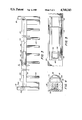
- FIG. 1 is a perspective view of a drop side crib fitted with a latch in accordance with this invention
- FIG. 2 is a fragmentary view, partially in section, of a portion of the top rail of the crib of FIG. 1 and the operating portion of the latch of this invention;
- FIG. 3 is a fragmentary front-elevational view of the upper portion of a crib having a latch in accordance with this invention
- FIG. 4 is a section taken along lines 4--4 of FIG. 3;
- FIG. 5 is an enlarged front-elevational view of the control mechanism shown in FIG. 3;
- FIG. 6 is an enlarged section taken along line 6--6 of FIG. 3, showing the latch in its locked position
- FIG. 7 is a partial view of the latch of FIG. 6 in its released position
- FIG. 8 is a section view taken from the top, of the end of the locking rod of this invention taken along line 8--8 of FIG. 9;
- FIG. 9 is a fragmentary side sectional view of the locking rod of FIG. 8;
- FIG. 10 is a side-elevational view, partly in section, of the end of the latching rod of this invention shown in FIG. 9 in its retracted position;
- FIG. 11 is a section taken along line 11--11 of FIG. 9 showing the latch plate of this invention in the front elevation.
- a drop side crib 10 has two ends 12 and 14 each end having a pair of supporting legs 16 and 18 respectively.
- a drop side 22 is releasably disposed between the ends and preferably includes top and bottom rails 26 and 28 and a barrier therebetween formed, for example, by a plurality of rods 30.
- a control assembly 34 for a latch mechanism for securing the drop side is disposed at approximately the center of the top rail.
- the control assembly 34 of the latch mechanism is illustrated in a fragementary perspective view in FIG. 2.
- the assembly 34 includes a combination track and outer housing member 38 that is attached to the top rail of the drop side by suitable fasteners, such as the two screws 40 visible in this figure and in FIGS. 6 and 7.
- the housing member 38 includes a two rail track 42 including two upstanding L-shaped rail members carrying a slidable control member 44 only a portion of which is seen in FIG. 2.
- the housing has a hood 39 closing one end.
- the slidable control member has a button portion 48 formed on a live hinge 50, as most readily seen in FIG. 5.
- a shuttle 52 is disposed in an elongated groove 56 cut in the rear surface of rail 26.
- the shuttle is generally H-shaped in cross section and includes two slots 58, 60, each receiving the bent over end of one of a pair of retractable locking rods 64, 66, as may be more clearly seen in FIG. 3.
- the shuttle has an actuating lug 70 attached thereto that extends through a slot 72 in the top rail 26, that allows the shuttle to operatively communicate with the slidable control member 44 (control slide).
- the upper surface of the actuating lug 70 has a shoulder 76 for engaging a complementary surface on the button 48 and ramp 78 for guiding the button over the actuating lug 70 when the control slide 44 is moved from right to left as seen in FIG. 2, even though the button 48 is depressed slightly.
- the control slide member 44 is formed from upper and lower members 82, 84 held together by screws 86 or similar fasteners as is most clearly seen in FIGS. 6 and 7.
- the lower control slide member 82 engages the underneath side of the upstanding rails of the two rail track 42, while the upper control slide member 44 engages the upper surface of the outer housing member 38 adjacent to the rails, as is most clearly seen in FIG. 2.
- the slidable control member 44 is thereby slidably retained on the track.
- the shuttle 52 is connected to one end of each of the retractable locking rods 64, 66 which are preferably carried in grooves 88, 89 formed in the back of the top rail extending to the left and right edges of the rail and communicating with the shuttle groove 56.
- the right locking rod 66 is connected to a bell crank assembly 90 that is pivotally mounted on the top rail, so that moving the control slide 44 from left to right as shown in FIG. 3 simultaneously retracts both locking rods.
- the structure of the ends of the locking rods and their interaction with plates that are attached to the ends of the crib will be more completely discussed in connection with FIGS. 8-11.
- FIGS. 4 and 5 show the control button 48 formed adjacent the left edge of the control slide 44 and surrounded by a groove 92 on 3 sides to provide a resilient hinged button structure that can be depressed to cause the button to engage the actuating lug 70 on the slidable shuttle 52. If the control slide 44 is moved from left to right without depressing the button 48, then the button passes over the top of the lug and does not move the shuttle and release the locking rods. Only by depressing the button before moving the control slide will the drop side of the crib be released. This may be more clearly seen by reference to FIGS. 6 and 7 that show the control assembly of the shuttle in section.
- the latch assembly is shown with the control slide 44 in its normal position.
- the retractable locking rods 64, 66 are extended and the drop side is locked in place. If the control slide 44 is simply moved to the right as if to retract the locking bars but the button is not depressed, the actuating lug engaging portion 96 of the button 48 will pass over the top of the lug 70 as the control slide 44 is moved from left to right, and the shuttle will remain in the locked position shown in FIG. 6. In order to retract the locking rods, the button 48 must be depressed as shown in FIG.
- the outer housing member 38 is also fastened to the upper rail of the drop side by additional screws 100 that engage bosses 102, 104 extending into the rail.
- a triple acting release mechanism may also be provided as shown in FIGS. 8 through 11.
- the free end 110 of the retractable locking rod 64 is preferably bent at approximately a right-angle and joined to the shaft 114 of a locking member 116.
- the end of rod 64 may be swedged or pinned to hold it in place as is well known.
- the locking member 116 is reciprocally mounted in a sleeve 120 attached to the end of the top rail 26 of the drop side 22.
- the sleeve 120 is received in a bore 124 communicating with the groove 88 in which the retractable locking rod 64 moves.
- the sleeve has an intermediate flange 126 bearing against the end of the top rail 26 for limiting the insertion of the sleeve 120 into the bore 124; and a notch 130 for engaging a pin or key 132 for holding the sleeve in position with respect to the rail 26.
- the remote end of the sleeve 120 includes a U-shaped recess 140 for receiving the enlarged head 142 of the locking member 116 when the member is retracted.
- a spring 144 engaging the locking member and a should 145 in the top rail biases the locking member to its extended position, as shown in FIGS. 7 and 8.
- a locking plate 150 as seen in an elevational view in FIG. 11 has a generally key-hole shaped opening 152 therein, the lower portion 154 of which is slightly larger than the shaft 114 of the locking member 116, but smaller than the head 142 thereof, so that the locking member cannot be retracted when the shaft 114 is resting in the lower portion of the keyhole opening 152.
- the drop side In order to retract the shaft, the drop side must be lifted slightly, so that the head 142 of the locking member is raised above the lower portion of the keyhole-shaped opening, whereupon the head can be withdrawn from the opening and the drop side released.
- a small tab 160 on the locking plate 150 is bent at approximately a 90° angle at the top of the opening, to prevent the enlarged head of the shaft from becoming caught behind the upper portion of the locking plate when the drop side of the crib is raised.
- a recess 162 cut in the leg 16 of the crib 10 receives the tab portion 160 of the locking plate, as well as the head of the locking membert.
- the locking plate 150 is preferably held in position with screws 164 or similar fasteners.
- the locking plate assembly shown in FIGS. 8-11 is repeated at spaced apart intervals along the ends of the crib.
- the locking plate assembly shown in FIGS. 8-11 is repeated at spaced apart intervals along the ends of the crib.
- only the ability to swing the drop side out of the way beneath the crib is required, then only a single locking plate assembly is needed.
Abstract
Description
Claims (24)
Priority Applications (5)
| Application Number | Priority Date | Filing Date | Title |
|---|---|---|---|
| US07/107,377 US4768243A (en) | 1987-10-09 | 1987-10-09 | Latch for a drop side crib |
| AU22994/88A AU2299488A (en) | 1987-10-09 | 1988-09-30 | Latch for a drop side crib |
| FR8813125A FR2621658B1 (en) | 1987-10-09 | 1988-10-06 | LOCK FOR A BABY WITH A FLIP-DOWN WALL |
| DE19883834238 DE3834238A1 (en) | 1987-10-09 | 1988-10-07 | LOCK FOR A CHILD BED WITH LOWERING SIDES |
| GB8823661A GB2210926A (en) | 1987-10-09 | 1988-10-07 | Latch for a drop side crib |
Applications Claiming Priority (1)
| Application Number | Priority Date | Filing Date | Title |
|---|---|---|---|
| US07/107,377 US4768243A (en) | 1987-10-09 | 1987-10-09 | Latch for a drop side crib |
Publications (1)
| Publication Number | Publication Date |
|---|---|
| US4768243A true US4768243A (en) | 1988-09-06 |
Family
ID=22316325
Family Applications (1)
| Application Number | Title | Priority Date | Filing Date |
|---|---|---|---|
| US07/107,377 Expired - Fee Related US4768243A (en) | 1987-10-09 | 1987-10-09 | Latch for a drop side crib |
Country Status (5)
| Country | Link |
|---|---|
| US (1) | US4768243A (en) |
| AU (1) | AU2299488A (en) |
| DE (1) | DE3834238A1 (en) |
| FR (1) | FR2621658B1 (en) |
| GB (1) | GB2210926A (en) |
Cited By (18)
| Publication number | Priority date | Publication date | Assignee | Title |
|---|---|---|---|---|
| US4924539A (en) * | 1989-10-17 | 1990-05-15 | Benoit Roland A | Child's crib |
| US5072464A (en) * | 1987-11-06 | 1991-12-17 | Simmons Juvenile Products Company, Inc. | Crib dropside including latch mechanism |
| US5134734A (en) * | 1991-05-22 | 1992-08-04 | Mibb, S.R.L. | Crib with positionable and sliding railings |
| US5432962A (en) * | 1994-04-20 | 1995-07-18 | Huang; Cheng-Kuei | Adjusting means for a railing side of a child's cot |
| US5511257A (en) * | 1994-08-19 | 1996-04-30 | The Brewer Company | Counterbalanced gate for a hospital youth crib and method for using the same |
| US5700494A (en) * | 1992-11-25 | 1997-12-23 | 9000-9226 Quebec Inc. | Device for producing a shaped confection of edible materials combined into co-extensive strips |
| US6088851A (en) * | 1997-05-06 | 2000-07-18 | Simmons Juvenile Products Company, Inc. | Crib dropside assembly including rail end fittings for engaging and sheilding corner posts tracks |
| WO2005041724A1 (en) * | 2003-10-24 | 2005-05-12 | David William Lugton | Latch mechanism |
| US20060021135A1 (en) * | 2004-07-26 | 2006-02-02 | Harvey A C | Cabinet-crib combination apparatus |
| USD666470S1 (en) | 2011-06-08 | 2012-09-04 | Foundations Worldwide, Inc. | Latch for a crib |
| US8336136B1 (en) | 2010-11-09 | 2012-12-25 | Susanne Debora Lantos | Panel assembly for a partial drop-side crib |
| US8572775B1 (en) | 2010-10-27 | 2013-11-05 | Foundations Worldwide, Inc. | Crib |
| USD732869S1 (en) | 2011-05-25 | 2015-06-30 | Foundations Worldwide, Inc. | Crib |
| US9380884B2 (en) | 2010-10-27 | 2016-07-05 | Foundations Worldwide, Inc | Crib |
| FR3032871A1 (en) * | 2015-02-24 | 2016-08-26 | Bessiere | DEVICE FOR LOCKING A SLIDING BARRIER FOR BEDS |
| RU2758332C2 (en) * | 2017-01-25 | 2021-10-28 | Артсана С.П.А. | Child bed |
| US20220007853A1 (en) * | 2018-11-21 | 2022-01-13 | China Wonderland Nurserygoods Co., Ltd. | Baby bed |
| WO2023055575A1 (en) * | 2021-09-28 | 2023-04-06 | Hb Innovations, Inc. | Crib panel assembly system |
Families Citing this family (3)
| Publication number | Priority date | Publication date | Assignee | Title |
|---|---|---|---|---|
| AU649367B2 (en) * | 1992-01-03 | 1994-05-19 | Ian Dickson Smith | Toddler crib and bed conversion cot |
| US6704951B2 (en) * | 2001-07-03 | 2004-03-16 | Community Products, Llc | Crib |
| DE602006004324D1 (en) * | 2006-06-13 | 2009-01-29 | Creations Mathou Jean Pierre | cot |
Citations (24)
| Publication number | Priority date | Publication date | Assignee | Title |
|---|---|---|---|---|
| US1275762A (en) * | 1916-10-14 | 1918-08-13 | Barcalo Mfg Co | Child's crib and the like. |
| US1465414A (en) * | 1922-11-04 | 1923-08-21 | Charles H Boardman | Crib |
| US1557013A (en) * | 1924-10-18 | 1925-10-13 | Charles H Boardman | Crib |
| US1612080A (en) * | 1924-03-07 | 1926-12-28 | Waddington John | Drop side cot |
| US1622387A (en) * | 1924-10-08 | 1927-03-29 | Frederick C Marquardt | Crib latch |
| US1705851A (en) * | 1927-02-17 | 1929-03-19 | Roman B Bukolt | Side-locking means for bassinets |
| US2011909A (en) * | 1933-08-25 | 1935-08-20 | Frank S Rece | Crib |
| US2369834A (en) * | 1943-02-03 | 1945-02-20 | Walfred L Lundin | Child's crib |
| US2448317A (en) * | 1944-09-27 | 1948-08-31 | Bolling B Lineberry | Infant's crib |
| US2473914A (en) * | 1945-02-24 | 1949-06-21 | F A Whitney Carriage Company | Latch for drop-side cribs |
| US2599663A (en) * | 1948-04-24 | 1952-06-10 | Alma W Schutzer | Side rail for beds |
| US2640203A (en) * | 1948-06-11 | 1953-06-02 | Werner H Sheldon | Cabinet type folding crib |
| US2979738A (en) * | 1958-07-02 | 1961-04-18 | Harold D Goldberg | Bed rail |
| US3541619A (en) * | 1968-06-28 | 1970-11-24 | Harry H Morrison | Drop side crib |
| US3634894A (en) * | 1969-12-12 | 1972-01-18 | Ingress Mfg Corp | Crib construction |
| US3649673A (en) * | 1970-06-01 | 1972-03-14 | Dow Chemical Co | Vinyl and allyl carbamates |
| US3786524A (en) * | 1970-02-27 | 1974-01-22 | M Mathou | Beds with lateral sliding panels |
| US3846854A (en) * | 1973-10-09 | 1974-11-12 | Gem Industries | Safety trip lock for cribs |
| US3896514A (en) * | 1974-07-01 | 1975-07-29 | Morris Feldstein | Securing apparatus for a dropside crib |
| US3900907A (en) * | 1974-06-24 | 1975-08-26 | Mariton Limited | Baby crib |
| US3934282A (en) * | 1974-09-10 | 1976-01-27 | Gem Industries, Inc. | Safety trip lock for the drop side of a crib |
| US4530528A (en) * | 1983-02-22 | 1985-07-23 | Louis Shamie | Double action crib drop side lock |
| US4703524A (en) * | 1984-12-28 | 1987-11-03 | Simmons Universal Corporation | Crib |
| US4706312A (en) * | 1984-11-20 | 1987-11-17 | Louis Shamie | Double action crib drop side lock and mattress support |
Family Cites Families (1)
| Publication number | Priority date | Publication date | Assignee | Title |
|---|---|---|---|---|
| GB495855A (en) * | 1936-02-14 | 1938-11-21 | Karel Bauer | Improvements relating to locks for use with doors, drawers and the like |
-
1987
- 1987-10-09 US US07/107,377 patent/US4768243A/en not_active Expired - Fee Related
-
1988
- 1988-09-30 AU AU22994/88A patent/AU2299488A/en not_active Abandoned
- 1988-10-06 FR FR8813125A patent/FR2621658B1/en not_active Expired - Lifetime
- 1988-10-07 DE DE19883834238 patent/DE3834238A1/en not_active Withdrawn
- 1988-10-07 GB GB8823661A patent/GB2210926A/en not_active Withdrawn
Patent Citations (24)
| Publication number | Priority date | Publication date | Assignee | Title |
|---|---|---|---|---|
| US1275762A (en) * | 1916-10-14 | 1918-08-13 | Barcalo Mfg Co | Child's crib and the like. |
| US1465414A (en) * | 1922-11-04 | 1923-08-21 | Charles H Boardman | Crib |
| US1612080A (en) * | 1924-03-07 | 1926-12-28 | Waddington John | Drop side cot |
| US1622387A (en) * | 1924-10-08 | 1927-03-29 | Frederick C Marquardt | Crib latch |
| US1557013A (en) * | 1924-10-18 | 1925-10-13 | Charles H Boardman | Crib |
| US1705851A (en) * | 1927-02-17 | 1929-03-19 | Roman B Bukolt | Side-locking means for bassinets |
| US2011909A (en) * | 1933-08-25 | 1935-08-20 | Frank S Rece | Crib |
| US2369834A (en) * | 1943-02-03 | 1945-02-20 | Walfred L Lundin | Child's crib |
| US2448317A (en) * | 1944-09-27 | 1948-08-31 | Bolling B Lineberry | Infant's crib |
| US2473914A (en) * | 1945-02-24 | 1949-06-21 | F A Whitney Carriage Company | Latch for drop-side cribs |
| US2599663A (en) * | 1948-04-24 | 1952-06-10 | Alma W Schutzer | Side rail for beds |
| US2640203A (en) * | 1948-06-11 | 1953-06-02 | Werner H Sheldon | Cabinet type folding crib |
| US2979738A (en) * | 1958-07-02 | 1961-04-18 | Harold D Goldberg | Bed rail |
| US3541619A (en) * | 1968-06-28 | 1970-11-24 | Harry H Morrison | Drop side crib |
| US3634894A (en) * | 1969-12-12 | 1972-01-18 | Ingress Mfg Corp | Crib construction |
| US3786524A (en) * | 1970-02-27 | 1974-01-22 | M Mathou | Beds with lateral sliding panels |
| US3649673A (en) * | 1970-06-01 | 1972-03-14 | Dow Chemical Co | Vinyl and allyl carbamates |
| US3846854A (en) * | 1973-10-09 | 1974-11-12 | Gem Industries | Safety trip lock for cribs |
| US3900907A (en) * | 1974-06-24 | 1975-08-26 | Mariton Limited | Baby crib |
| US3896514A (en) * | 1974-07-01 | 1975-07-29 | Morris Feldstein | Securing apparatus for a dropside crib |
| US3934282A (en) * | 1974-09-10 | 1976-01-27 | Gem Industries, Inc. | Safety trip lock for the drop side of a crib |
| US4530528A (en) * | 1983-02-22 | 1985-07-23 | Louis Shamie | Double action crib drop side lock |
| US4706312A (en) * | 1984-11-20 | 1987-11-17 | Louis Shamie | Double action crib drop side lock and mattress support |
| US4703524A (en) * | 1984-12-28 | 1987-11-03 | Simmons Universal Corporation | Crib |
Cited By (23)
| Publication number | Priority date | Publication date | Assignee | Title |
|---|---|---|---|---|
| US5072464A (en) * | 1987-11-06 | 1991-12-17 | Simmons Juvenile Products Company, Inc. | Crib dropside including latch mechanism |
| US4924539A (en) * | 1989-10-17 | 1990-05-15 | Benoit Roland A | Child's crib |
| US5134734A (en) * | 1991-05-22 | 1992-08-04 | Mibb, S.R.L. | Crib with positionable and sliding railings |
| US5700494A (en) * | 1992-11-25 | 1997-12-23 | 9000-9226 Quebec Inc. | Device for producing a shaped confection of edible materials combined into co-extensive strips |
| US5432962A (en) * | 1994-04-20 | 1995-07-18 | Huang; Cheng-Kuei | Adjusting means for a railing side of a child's cot |
| US5511257A (en) * | 1994-08-19 | 1996-04-30 | The Brewer Company | Counterbalanced gate for a hospital youth crib and method for using the same |
| US6088851A (en) * | 1997-05-06 | 2000-07-18 | Simmons Juvenile Products Company, Inc. | Crib dropside assembly including rail end fittings for engaging and sheilding corner posts tracks |
| WO2005041724A1 (en) * | 2003-10-24 | 2005-05-12 | David William Lugton | Latch mechanism |
| US20060021135A1 (en) * | 2004-07-26 | 2006-02-02 | Harvey A C | Cabinet-crib combination apparatus |
| US7069605B2 (en) | 2004-07-26 | 2006-07-04 | Harvey Iii Archie | Cabinet-crib combination apparatus |
| US9380884B2 (en) | 2010-10-27 | 2016-07-05 | Foundations Worldwide, Inc | Crib |
| US8572775B1 (en) | 2010-10-27 | 2013-11-05 | Foundations Worldwide, Inc. | Crib |
| US8745781B1 (en) | 2010-10-27 | 2014-06-10 | Foundations Worldwide, Inc. | Crib |
| US8336136B1 (en) | 2010-11-09 | 2012-12-25 | Susanne Debora Lantos | Panel assembly for a partial drop-side crib |
| USD732869S1 (en) | 2011-05-25 | 2015-06-30 | Foundations Worldwide, Inc. | Crib |
| USD666470S1 (en) | 2011-06-08 | 2012-09-04 | Foundations Worldwide, Inc. | Latch for a crib |
| FR3032871A1 (en) * | 2015-02-24 | 2016-08-26 | Bessiere | DEVICE FOR LOCKING A SLIDING BARRIER FOR BEDS |
| RU2758332C2 (en) * | 2017-01-25 | 2021-10-28 | Артсана С.П.А. | Child bed |
| US20220007853A1 (en) * | 2018-11-21 | 2022-01-13 | China Wonderland Nurserygoods Co., Ltd. | Baby bed |
| EP3884811A4 (en) * | 2018-11-21 | 2022-04-20 | China Wonderland Nurserygoods Co., Ltd. | Baby bed |
| AU2019382420B2 (en) * | 2018-11-21 | 2023-05-11 | China Wonderland Nurserygoods Co., Ltd. | Baby bed |
| WO2023055575A1 (en) * | 2021-09-28 | 2023-04-06 | Hb Innovations, Inc. | Crib panel assembly system |
| US11832736B2 (en) | 2021-09-28 | 2023-12-05 | Hb Innovations, Inc. | Crib panel assembly system |
Also Published As
| Publication number | Publication date |
|---|---|
| DE3834238A1 (en) | 1989-04-20 |
| FR2621658B1 (en) | 1990-08-31 |
| GB2210926A (en) | 1989-06-21 |
| GB8823661D0 (en) | 1988-11-16 |
| AU2299488A (en) | 1989-04-13 |
| FR2621658A1 (en) | 1989-04-14 |
Similar Documents
| Publication | Publication Date | Title |
|---|---|---|
| US4768243A (en) | Latch for a drop side crib | |
| US5257860A (en) | Drawer lock mechanism including push button latch | |
| US7627985B2 (en) | Gate latch assembly | |
| USRE40267E1 (en) | Drawer latch | |
| US6276092B1 (en) | Combined sliding and pivot window assembly | |
| US20090127872A1 (en) | Compact sliding sash lock | |
| JPS6012847Y2 (en) | drawer latch device | |
| US3883200A (en) | File drawer lock | |
| US5390516A (en) | Pushbutton lock for sliding doors | |
| EP0305081B1 (en) | A retractable window covering assembly | |
| US4813251A (en) | Four point locking system for storage cabinets | |
| US4333690A (en) | Slide mechanism | |
| JP3555268B2 (en) | Locking device for shutter | |
| US3774985A (en) | File locking mechanism | |
| US20070241651A1 (en) | Drawer slide with releasable latch | |
| US4303288A (en) | Drawer locking apparatus for merchandise cabinets | |
| JP2754041B2 (en) | Doors for furniture etc. | |
| US20220010615A1 (en) | Security Gate | |
| US3957324A (en) | Drawer cabinet anti-tip device | |
| US2597056A (en) | Window lock | |
| JP3508974B2 (en) | Selectable locking device for doors and drawers in cabinets | |
| US3088176A (en) | Folding bleacher | |
| KR200456204Y1 (en) | Apparatus for locking safety window | |
| US2689607A (en) | Venetian blind fitting | |
| JP3198812B2 (en) | Drawer latch device |
Legal Events
| Date | Code | Title | Description |
|---|---|---|---|
| AS | Assignment |
Owner name: QUAKER OATS COMPANY, THE, 321 NORTH CLARK STREET, Free format text: ASSIGNMENT OF ASSIGNORS INTEREST.;ASSIGNOR:WAPLES, DAVID G.;REEL/FRAME:004808/0193 Effective date: 19871119 |
|
| AS | Assignment |
Owner name: FISHER - PRICE, INC., 636 GIRARD AVENUE E. AURORA, Free format text: ASSIGNMENT OF ASSIGNORS INTEREST.;ASSIGNOR:QUAKER OATS COMPANY, THE, A CORP. OF NJ;REEL/FRAME:005570/0174 Effective date: 19901206 |
|
| REMI | Maintenance fee reminder mailed | ||
| LAPS | Lapse for failure to pay maintenance fees | ||
| FP | Lapsed due to failure to pay maintenance fee |
Effective date: 19920906 |
|
| STCH | Information on status: patent discontinuation |
Free format text: PATENT EXPIRED DUE TO NONPAYMENT OF MAINTENANCE FEES UNDER 37 CFR 1.362 |