US4768405A - Locking socket wrench drive device - Google Patents
Locking socket wrench drive device Download PDFInfo
- Publication number
- US4768405A US4768405A US07/045,781 US4578187A US4768405A US 4768405 A US4768405 A US 4768405A US 4578187 A US4578187 A US 4578187A US 4768405 A US4768405 A US 4768405A
- Authority
- US
- United States
- Prior art keywords
- socket
- control bar
- shank
- sleeve
- extension
- Prior art date
- Legal status (The legal status is an assumption and is not a legal conclusion. Google has not performed a legal analysis and makes no representation as to the accuracy of the status listed.)
- Expired - Lifetime
Links
Images


Classifications
-
- B—PERFORMING OPERATIONS; TRANSPORTING
- B25—HAND TOOLS; PORTABLE POWER-DRIVEN TOOLS; MANIPULATORS
- B25B—TOOLS OR BENCH DEVICES NOT OTHERWISE PROVIDED FOR, FOR FASTENING, CONNECTING, DISENGAGING OR HOLDING
- B25B15/00—Screwdrivers
- B25B15/001—Screwdrivers characterised by material or shape of the tool bit
-
- B—PERFORMING OPERATIONS; TRANSPORTING
- B25—HAND TOOLS; PORTABLE POWER-DRIVEN TOOLS; MANIPULATORS
- B25B—TOOLS OR BENCH DEVICES NOT OTHERWISE PROVIDED FOR, FOR FASTENING, CONNECTING, DISENGAGING OR HOLDING
- B25B23/00—Details of, or accessories for, spanners, wrenches, screwdrivers
- B25B23/0007—Connections or joints between tool parts
- B25B23/0035—Connection means between socket or screwdriver bit and tool
-
- B—PERFORMING OPERATIONS; TRANSPORTING
- B25—HAND TOOLS; PORTABLE POWER-DRIVEN TOOLS; MANIPULATORS
- B25G—HANDLES FOR HAND IMPLEMENTS
- B25G3/00—Attaching handles to the implements
- B25G3/02—Socket, tang, or like fixings
- B25G3/12—Locking and securing devices
- B25G3/18—Locking and securing devices comprising catches or pawls
-
- Y—GENERAL TAGGING OF NEW TECHNOLOGICAL DEVELOPMENTS; GENERAL TAGGING OF CROSS-SECTIONAL TECHNOLOGIES SPANNING OVER SEVERAL SECTIONS OF THE IPC; TECHNICAL SUBJECTS COVERED BY FORMER USPC CROSS-REFERENCE ART COLLECTIONS [XRACs] AND DIGESTS
- Y10—TECHNICAL SUBJECTS COVERED BY FORMER USPC
- Y10T—TECHNICAL SUBJECTS COVERED BY FORMER US CLASSIFICATION
- Y10T403/00—Joints and connections
- Y10T403/59—Manually releaseable latch type
- Y10T403/599—Spring biased manipulator
Definitions
- Socket wrenches incorporating ratchet drives and standard sockets for driving threaded fasteners including most commonly hexagonal nuts and bolt heads are commonly used in the mechanic's field.
- extension drives are utilized to transmit the force from the ratchet to the socket.
- fastener drive sockets can be affixed to mechanisms with which to drive those sockets.
- Most of the known systems involve methods tailored to specific needs providing positive locking mechanisms for tools such as impact wrenches, where it is essential from a safety standpoint to have the sockets firmly attached to the drive.
- complicated machining may be utilized since the drive mechanisms are of relatively large size and bulk providing adequate strength despite extensive internal machining.
- these mechanisms are all devised to be utilized in a location where the operator is provided ample work space and compactness of the mechanism is not an important factor.
- Known mechanisms incorporate locking means such as external rotating collars which are unsuitable for application in close quarters due to the possibility of accidental release from friction with obstructions (Rhinevault U.S. Pat. No.
- One other type of mechanism known in an application similar to that for the instant invention is a push button release for a ratchet socket drive.
- This mechanism is unlike the invention in that it requires relatively complicated machining as does the other prior art, is relatively difficult to maintain and subject to malfunction from dirt or wear, is unsuitable for use on extensions because of the utilization of a central axial bore and pushbutton, and finally, involves application of both a downward pressure on a pushbutton plunger while requiring the resistance against which this force is applied as well as the simultaneous movement of the socket in the same direction as the pushbutton and in the direction opposite the resistance, which is an awkward motion for a mechanic in tight spaces.
- the pushbutton ratchet release also requires that the mechanism be machined out of larger pieces for the same strength as non-machined parts, rendering it frequently difficult to utilize the ratchet and socket combination alone in tight spaces (Smyers U.S. Pat. No. 3,762,245).
- the invention provides for the utilization of the locking and quick releasing feature as a supplement to the ratchet handle which may be made smaller yet stronger than the cumbersome quick release type ratchet handle.
- a socket wrench drive extension is designed for use in conjunction with a ratchet drive handle and standard sockets for driving threaded fasteners.
- the extension incorporates a longitudinal control bar channel machined in one phase of the square drive portion of the socket and extending past the shoulder separating the driven portion from the extension portion of the device.
- a control bar is incorporated which is slidably mounted within the machined control bar channel, moving longitudinally therein.
- the lower end of the control bar is machined in the preferred embodiment, being beveled at an angle of approximately 15'-30' and being narrower at the lower of the control bar.
- the control bar comprises a flat portion contiguous to the inclined portion.
- the inclined portion is of a dimension longitudinally such that the lower-most portion of the control bar does not extend past the lower-most portion of the extension drive portion when the control bar is deflected fully forward or downward, while the upper edge of the inclined portion of the control bar at full forward or downward deflection does not extend as far as the bearing menas which transmit the lateral force from the control bar to the detent and thereafter maintaining the socket in locked position until release.
- the flat portion of the control bar comes in contact with the locking ball bearing thereby locking the detent in position against the wall of the socket and the retainer groove machined therein.
- a detent or retainer ball is slidably carried in the transverse aperture of the drive portion of the extension which when in locked position against the locking bearing ball and control bar exerts lateral force against the detent extending past the face in the square drive portion of the extension opposite the face into which the control bar channel is machined.
- the lateral extension of this detent mates with standard recesses machined in the drive walls of standard sockets and prevents the downward or forward movement of said sockets.
- the outward extension of the detent further serves to lock the socket in position with relation to the drive axis of the extension in that lateral pressure is exerted on the drive wall of the socket by the detent in its locked position and the control bar along with the opposite face of the drive wall of the socket.
- the mechanism is maintained in its locked position through the use of a spring exerting forward or downward pressure against the release collar and locked in its forward extension through the use of circular clip ring or clamp.
- An additional embodiment utilizes the device herein described with modifications so as to provide for a locking and release action at both the driven end of a socket wrench drive shank and the driving end.
- the sliding collar has been rearwardly extended and is of a dimension sufficient to be slidably carried relative to the outside diameter of the driven portion of the placement of a fixedly mounted pin in the surface of the shank, said pin intersecting a generally L-shaped slot in the collar, although other fastening means could be used.
- the L-shaped slot permits limited forward and rearward travel and limited rotational travel.
- the further modification of the sleeve to encompass this embodiment includes the placement of one or more grooves or recesses in the inner surface of the sleeve in the section where it rearwardly extends over the surface of the driven end of the shank. These recesses permit the retraction of a retainer ball placed in said driven end.
- the recesses are so oriented such that the rotation and rearward movement of the sleeve results in the exertion of inward pressure on the driven end retainer ball or balls.
- the device can function as an adaptor, rather than a mere quick release provision on the end of an extension of a fixed length.
- the quick release and locking features may be utilized in complete compatibility with a mechanic's existing set of driving tools, particularly with extensions of varied lengths.
- the driven end locking feature provides a positive locking action thus avoiding unwanted release of the device itself or the tools attached to the driving end of the device.
- FIG. 1 is a perspective view of the invention and a standard socket in the release position.
- FIG. 2 is a perspective view of the invention and a standard socket in the locked position.
- FIG. 3 is a fragmentary sectional view of the invention in its released position.
- FIG. 4 in a fragmentary sectional view of the invention in its locked position shown in conjunction with a standard socket.
- FIG. 5 is an exploded perspective view of the invention showing its parts in relation to each other.
- FIG. 6 is a perspective view of the device as adapted to a power socket wrench drive device through the use of a yoke and bearing.
- FIG. 7 is a fragmentary sectional view of the device in its embodiment utilizing a retainer ball and single bearing ball.
- FIG. 8 is a fragmentary sectional view of the device utilizing a multiplicity of ball bearings as force transmittal device.
- FIG. 9 is a fragmentary sectional view of an embodiment of the device utilizing a single retention member of generally cylindrical configuration.
- FIG. 10 constitutes a perspective view of the device in its double locking embodiment in the locked position.
- FIG. 11 constitutes a fragmentary sectional view of the device in its double locking embodiment in the released position.
- FIG. 12 constitutes a fragmentary sectional view of the device in its double locking embodiment in the locked position.
- FIG. 13 constitutes an exploded view of the device in its double locking embodiment, further demonstrating the method of assembly and disassembly.
- FIG. 14 shows an exaggerated sectional view of an alternate embodiment of the device with a retaining ball and a bearing ball in the locked position.
- FIG. 1 a socket wrench drive extension including a driven portion of the socket drive extension 11, the socket wrench drive extension shank 9, and the driving portion of the socket wrench drive extension 12.
- the socket wrench drive extension is designed to be driven by the square drive portion of a standard ratchet handle mating with the drive portion 11.
- the socket wrench drive extension 12 drives a standard socket 21 which mates with the driving portion of the socket wrench extension 12.
- control bar channel 10 Machined in the surface of the socket wrench drive extension shank 9 is a control bar channel 10 which channel extends to a substantial portion of the shank 9 through the shoulder 27 between the shank 9 which is cylindrical in cross-section and the driving portion 12 which is square in cross-section.
- the control bar 14 includes the outer positive locking and centering portion 13 at its lower end.
- the sleeve engagement spur 16 is an integral part of the control bar 14 which is located equidistant from the end of the control bar and serves to engage the control bar with the sleeve 15.
- the sleeve 15 includes internally machined control bar engagement spurs 28 which transmit motion from the sleeve 15 to control bar 14.
- Internal of the sleeve is a heical spring 17 which bears on the upper portion of the control bar engagement means 28 at the lower end of the spring 17 while being retained by a C-clip 18 fitting a groove 30 machined in the circumference of the drive extension shank 9.
- the helical spring 17 is shown in its compressed position in FIG. 1 as the sleeve 15 is pulled axially toward the driven end of the extension shaft 11 and away from the driving end of the extension shaft 12 through a force exerted directionally upward or backward by the user against the grippable portion 29 machined into the exterior of the sleeve.
- the rearward displacement of the sleeve and connected control bar accomplish the operation as demonstrated in greater detail in FIG. 3 and 4.
- the control bar release face 25 then releases the ball detent mechanism thereby releasing the standard fastener driving socket wrench 21.
- FIG. 2 is a perspective view which shows the preferred embodiment in position for use with the sleeve 15 released by the user and forced downward by the spring 17.
- the sleeve 15 As the sleeve 15 is forced downward it in turn forces the control bar 14 downward through the engagement spurs 16 and 28 which displaces the locking mechanism outward and retains the socket 21 in a locked position.
- the maximum extension of the control mechanism including the sleeve 15, spring 17 and control bar sleeve engagement spur 16 is restricted by a C-clip or circlip 18 fitted in a circumferential groove 30 machined in the shank 9 of the extension drive shaft.
- other fastening means can be substituted for C-clips.
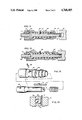
- FIG. 3 is a fragmentary cross-sectional view of the preferred embodiment showing the lower portion of the drive extension shank 9, the square driving portion of the socket wrench drive extension shaft 12.
- the lower locking portion of the control bar 14 which comprises the outer positive locking and centering portion of the control bar 13, as well as the beveled release surface 25 of the control bar 14.
- the transverse bore 19 positioned in such a way as to intersect the control bar channel 10.
- This transverse bore 19 is knurled or otherwise machined at either end to decrease the diameter of the bore so as to retain the locking bearing ball 24, the transmission shaft 23 for transmitting the locking force to the retainer ball 22, and retainer ball 24.
- FIG. 3 shows the preferred embodiment in the spring-compressed position as in FIG. 1 which permits the retainer mechanism ball bearings 22 and 24, and force transmission shaft 23 free to be displaced radially through the transverse bore toward the control bar channel thereby permitting the removal of the socket.
- the C-clips 18 further serve to provide radial pressure against the outer surface of the control bar 14 to prevent its displacement outward, as does the inner wall of the sleeve 15.
- FIG. 4 is fragmentary sectional view showing the feature as described in FIG. 3 as well as the drive socket 21 which includes a recess 25 against which the retainer ball bearing 22 is forced through operation of the control bar.
- FIG. 4 shows the spring 17 in its extended configuration forcing the sleeve 15 downward through operation of the engagement spurs 28 and 16 to its maximum extension is restricted by the C-clips 18.
- the control bar 14 is also extended downward to its maximum operating extension point.
- the beveled release surface 25 of the control bar applies constant force accross the ball bearings 24 which through the force transmission shaft 23 extends the retainer ball 22 progressively farther outward on the opposite face the square socket drive portion 12.
- the flat interface 13 of the control bar 14 prevents further transverse movement of the locking mechanims 22, 23 and 24 by virtue of the fact that the force is acting approximately 90° in relationship to the locking surface of the control bar 32.
- any downward force on the socket while in the locked position is distributed evenly through the retainer ball 22 force transmittal shaft 23 and locking ballbearing 24 through the positive locking and centering portion of the control ball 13 to provide even forces on opposite inner walls 31 of the square drive of a standard socket which serves to center the socket so that as rotational forces act on the entire mechanism through the socket wrench drive extension shaft these forces are distributed approximately equally on or near each corner of the walls of the driving portion of the socket wrench drive extension shaft 12 and the driven inner walls 31 of the standard socket wrench 21.
- the centering action is desirable in general to transmit equal rotational forces and in particular in cases where the driven inner walls of standard sockets suffer from wear or being oversized.
- FIG. 5 is a perspective exploded view of the preferred embodiment showing the parts separately in relation to each other.
- FIG. 6 is a perspective view of an alternative embodiment in which the sleeve 15 is non-rotatably mounted relative to the drive shaft of a power driven socket wrench 32.
- the sleeve itself is mounted in a rotating bearing 33 through which the downward or rearward force is transmitted through a mechanism pivotally mounted at 35 on the casing of the power driven socket wrench, which mechanism utilizes a semi-circular yoke 36 around the drive shaft and sleeve.
- the exertion of force on the release lever 34 is transmitted through the bearing to the sleeve which in turn transmits the force through a mechanism as described in FIGS. 1-5 which provides a ready and quick means of releasing said sockets.
- FIG. 7 is a fragmentary sectional view of another embodiment in which the locking ball bearing 24 bears directly on the retainer ball 25 dispensing with the force transmission shaft.
- FIG. 8 is a fragmentary sectional view of another embodiment in which multiple ball bearings 37 are utilized to transmit force from the control bar to the retainer ball.
- FIG. 9 is a fragmentary sectional view in which a cylindrical detent 38 is utilized, extending completely through the transverse bore.
- FIG. 10 constitutes a perspective view of the device in its double locking configuration.
- Apparent in FIG. 10 are the common features including the sleeve, 29 and control bar, 14.
- the sleeve is rearwardly extended over the driven end of the shank. The rearward travel is permitted by and limited by a substantially L-shaped slot, 42, machined through the surface of the sleeve, 29. Retention of the sleeve is accomplished through the use of a pin 43, placed within the slot, 42, and fixedly mounted in the shank.
- FIG. 11 is a fragmentary sectional view of the device in its double locking embodiment in the released configuration.
- the interior of the rearward extension of the sleeve, 29, is provided with a recess or recesses, 40, into which the driven end locking ball, 41 is carried, and permitted to retract in the release configuration. Further apparent is the locking slot 42, and pin, 43.
- the operation of the driving end section, utilizing the detent, 38, engaging a drive socket, 21, acted upon by the control bar, 14 is substantially the same as the other embodiments.
- FIG. 12 is a fragmentary sectional view of the device in its double locking embodiment in the locked configuration.
- the detent, 38 engages the recess in the socket, 21.
- the downward or inward pressure of the sleeve 29 is exerted upon the driven end detent, 41 which detent itself mates with the standard detent of the driving member, 45. Because the detent in the driving member 45 is spring loaded, it can be compressed below the driving surface by the locking detent, 41.
- FIG. 13 constitutes an exploded view of the device showing the components in a disassembled configuration. Assembly and disassembly is generally accomplished through removal of the retainer pin, 43.
- FIG. 14 shows in exaggerated proportions the relationship of a two-ball detent arrangement in the locked position.
- the bearing ball 51 is supported in passage 53 in the shank 9 and engages the inward surface of control bar 14.
- Ball 51 engages the wall of the passage 53 and also engages retaining ball 55, forcing retaining ball 55 against the tapered end 57 of passage 53.
- the passage 53 is somewhat larger in diameter than the balls 51 and 55. As a result, the balls 51 and 55 do not line up and bearing ball 51 takes an eccentric position in the passage 53, as illustrated in FIG. 14. The eccentric position of the ball 51 results in a positive locking relationship between the balls.
Landscapes
- Engineering & Computer Science (AREA)
- Mechanical Engineering (AREA)
- Details Of Spanners, Wrenches, And Screw Drivers And Accessories (AREA)
Abstract
Description
Claims (14)
Priority Applications (2)
| Application Number | Priority Date | Filing Date | Title |
|---|---|---|---|
| US07/045,781 US4768405A (en) | 1981-05-04 | 1987-04-30 | Locking socket wrench drive device |
| US07/239,696 US4905549A (en) | 1981-05-04 | 1988-09-02 | Power driven wrench retention device |
Applications Claiming Priority (3)
| Application Number | Priority Date | Filing Date | Title |
|---|---|---|---|
| US06/260,350 US4480511A (en) | 1981-05-04 | 1981-05-04 | Locking socket wrench drive device |
| US63477584A | 1984-07-26 | 1984-07-26 | |
| US07/045,781 US4768405A (en) | 1981-05-04 | 1987-04-30 | Locking socket wrench drive device |
Related Parent Applications (1)
| Application Number | Title | Priority Date | Filing Date |
|---|---|---|---|
| US63477584A Continuation-In-Part | 1981-05-04 | 1984-07-26 |
Related Child Applications (1)
| Application Number | Title | Priority Date | Filing Date |
|---|---|---|---|
| US07/239,696 Continuation-In-Part US4905549A (en) | 1981-05-04 | 1988-09-02 | Power driven wrench retention device |
Publications (1)
| Publication Number | Publication Date |
|---|---|
| US4768405A true US4768405A (en) | 1988-09-06 |
Family
ID=27366752
Family Applications (1)
| Application Number | Title | Priority Date | Filing Date |
|---|---|---|---|
| US07/045,781 Expired - Lifetime US4768405A (en) | 1981-05-04 | 1987-04-30 | Locking socket wrench drive device |
Country Status (1)
| Country | Link |
|---|---|
| US (1) | US4768405A (en) |
Cited By (54)
| Publication number | Priority date | Publication date | Assignee | Title |
|---|---|---|---|---|
| US4905549A (en) * | 1981-05-04 | 1990-03-06 | 501 Qualicorp, Ltd | Power driven wrench retention device |
| WO1990002634A1 (en) * | 1988-09-06 | 1990-03-22 | Nickipuck Michael F | Locking socket wrench drive device |
| US4938107A (en) * | 1981-05-04 | 1990-07-03 | 501 Qualicorp, Ltd | Wedge locking socket device |
| US4943182A (en) * | 1988-03-14 | 1990-07-24 | Ecia - Equipments Et Composants Pour L'industrie Automobile | Rapid fastener of the bayonet type |
| US5211086A (en) * | 1992-07-07 | 1993-05-18 | Shu Zu S | Tool with sliding sleeve for ratchet direction control |
| AU650231B2 (en) * | 1988-09-06 | 1994-06-16 | Qualicorp, Ltd. | Locking socket wrench drive device |
| US5440955A (en) * | 1994-02-14 | 1995-08-15 | Freeland; Gregory A. | Multi-purpose strap wrench |
| US5503048A (en) * | 1994-09-20 | 1996-04-02 | Link Industries, Inc. | Quick release mechanism for tools such as socket wrenches |
| US5566595A (en) * | 1993-08-24 | 1996-10-22 | Socket Retainer Systems, Inc. | Socket mounting arrangement |
| US5720207A (en) * | 1996-11-12 | 1998-02-24 | Milner; W. Ross | Socket locking extension for wrench handle |
| US5813296A (en) * | 1996-09-26 | 1998-09-29 | Snap-On Technologies, Inc. | Quick release socket mechanism |
| US5836564A (en) * | 1996-05-23 | 1998-11-17 | Avibank Mfg., Inc | Fail safe hold open telescoping rod |
| US5934384A (en) * | 1998-04-27 | 1999-08-10 | Wang; Peter | Transmission shaft and bit mounting arrangement of a motor-driven hand drill |
| US6164169A (en) * | 1998-08-03 | 2000-12-26 | Socket Retainer Systems, Inc. | Socket mounting arrangement |
| US6167787B1 (en) | 1995-03-06 | 2001-01-02 | Jack D. Jarvis | Locking swivel wrench |
| US6263766B1 (en) | 1996-01-16 | 2001-07-24 | Jack D. Jarvis | Palm ratchet having releasably attached lateral handle |
| US6332384B1 (en) * | 2001-02-09 | 2001-12-25 | Gary Paul Cluthe | Multiple bit screwdriver |
| US6516689B1 (en) | 2000-11-08 | 2003-02-11 | Stride Tool, Inc. | Ratchet wrench |
| US20030047890A1 (en) * | 2001-09-10 | 2003-03-13 | Iwinski Dean J. | Locking drive tool |
| WO2003047817A1 (en) * | 2001-12-04 | 2003-06-12 | Joda Enterprises, Inc. | Quick release mechanism for tools such as socket wrenches |
| NL1021550C2 (en) * | 2002-09-27 | 2004-04-02 | Juan Manuel Luna Madue O | Coupling for e.g. securing mop head to shaft, has sliding actuator for locking or releasing fingers used to connect parts of coupling attached to e.g. mop head and shaft |
| US20040126182A1 (en) * | 2002-12-27 | 2004-07-01 | Yu-Cheng Lin | Connector |
| US20040220554A1 (en) * | 2000-06-24 | 2004-11-04 | Andre Lechot | Hand-held instrument holder for surgical use |
| US20050045002A1 (en) * | 2003-08-29 | 2005-03-03 | Cluthe Gary Paul | Multiple bit hand tool with automatic bit locking |
| US20050087938A1 (en) * | 2003-10-24 | 2005-04-28 | Lin Peng-Ho | Coupling tube for a screwdriver head |
| US20050229752A1 (en) * | 2004-04-20 | 2005-10-20 | Nickipuck Michael F | Low profile locking socket wrench universal joint |
| US20060201290A1 (en) * | 2005-03-08 | 2006-09-14 | Kinpack Polyethylene Ltd. | Multiple bit screwdriver |
| US20060201291A1 (en) * | 2005-03-11 | 2006-09-14 | Duron Plastics Limited | Multiple-bit driver with spring-loaded actuation |
| US20060201289A1 (en) * | 2005-03-10 | 2006-09-14 | Davidson John B | Tools for detachably engaging tool attachments |
| US7137514B1 (en) | 2002-09-06 | 2006-11-21 | Nickipuck Michael F | Storage rail connectors for ratchet wrench sockets |
| US20060280551A1 (en) * | 2003-05-16 | 2006-12-14 | Pineiros Victor M | Solid shank pawl pin with redundant locking system |
| US20070186729A1 (en) * | 2004-06-28 | 2007-08-16 | David Baker | Flush Socket Power Ratchet Tool System |
| WO2007133360A2 (en) | 2006-05-01 | 2007-11-22 | Joda Enterprises, Inc. | Coupling mechanisms for detachably engaging tool attachments |
| WO2007142779A2 (en) | 2006-06-02 | 2007-12-13 | Joda Enterprises, Inc. | Universal joint with coupling mechanism for detachably engaging tool attachments |
| US20110188922A1 (en) * | 2010-02-01 | 2011-08-04 | Hyclone Laboratories, Inc. | Quick coupling for drive shaft |
| US20120325509A1 (en) * | 2011-06-24 | 2012-12-27 | Black & Decker Inc. | Quick Release Socket Attachment For Impact Wrench |
| US8424424B1 (en) * | 2006-04-10 | 2013-04-23 | Nick C. Kravitch | Adaptor for interchangeable extention tool |
| US8484884B2 (en) * | 2004-07-26 | 2013-07-16 | Andrew Zuk | Fishing lure and kit |
| US20130192860A1 (en) * | 2011-06-24 | 2013-08-01 | Black & Decker Inc. | Electromagnetic mode change mechanism for power tool |
| US20140096654A1 (en) * | 2012-10-05 | 2014-04-10 | Lowell Corporation | Impact Socket |
| US8834484B2 (en) | 2011-11-14 | 2014-09-16 | Biomet Manufacturing, Llc | Surgical instrument including angle adjustment mechanism and quick-connect mechanism |
| US8857298B2 (en) | 2011-12-22 | 2014-10-14 | Joda Enterprises, Inc. | Tool release mechanism with spring-receiving guided element |
| US9408613B2 (en) | 2011-12-13 | 2016-08-09 | Biomet Manufacturing, Llc | Glenoid reamer |
| US20160263730A1 (en) * | 2012-10-05 | 2016-09-15 | Lowell Corporation | Impact Socket |
| US20160271767A1 (en) * | 2015-03-18 | 2016-09-22 | Hong Ann Tool Industries Co., Ltd. | Wrench with Adjustable Operating Angle |
| US9463559B1 (en) * | 2015-07-02 | 2016-10-11 | Fu-Yi Chan | Tool positioning device |
| US20180141193A1 (en) * | 2016-11-21 | 2018-05-24 | Yi-Fu Chen | Torque setting device for torque wrench |
| US20180207775A1 (en) * | 2015-05-08 | 2018-07-26 | Shun-Yee Industrial Co., Ltd. | Quick release device of hand tool |
| GB2561381A (en) * | 2017-04-12 | 2018-10-17 | Inventive Products Ltd | A clasp |
| US11215769B2 (en) | 2019-03-07 | 2022-01-04 | Mellanox Technologies, Ltd. | MPO locking |
| US11247254B2 (en) | 2019-02-26 | 2022-02-15 | Steven Hopf | Adjustable dent removal tool |
| US11311301B2 (en) | 2014-08-14 | 2022-04-26 | Biomet Manufacturing, Llc | Flexible bone reamer |
| US11370103B2 (en) * | 2014-01-17 | 2022-06-28 | Thunderchuck Innovations Inc. | Bit driving tool and device for use therewith |
| US11833563B2 (en) | 2019-02-26 | 2023-12-05 | Steven Hopf | Adjustable dent removal tool |
Citations (7)
| Publication number | Priority date | Publication date | Assignee | Title |
|---|---|---|---|---|
| US1864466A (en) * | 1930-09-10 | 1932-06-21 | John N Peterson | Tool holder |
| US2162359A (en) * | 1936-08-22 | 1939-06-13 | Armstrong Bros Tool Co | Lock for socket wrenches, etc. |
| US2743639A (en) * | 1952-09-25 | 1956-05-01 | Farrel Birmingham Co Inc | Stud setter |
| US3172675A (en) * | 1963-02-19 | 1965-03-09 | Victor E Gonzalez | Ball socket attachment for impact tool |
| US3455586A (en) * | 1964-07-31 | 1969-07-15 | Klingelnberg Soehne Ferd | Connection of circular knives on smooth shafts |
| US4070932A (en) * | 1977-03-01 | 1978-01-31 | Jeannotte Richard W | Extensible handle for a tool headpiece |
| US4480511A (en) * | 1981-05-04 | 1984-11-06 | Nickipuck Michael F | Locking socket wrench drive device |
-
1987
- 1987-04-30 US US07/045,781 patent/US4768405A/en not_active Expired - Lifetime
Patent Citations (7)
| Publication number | Priority date | Publication date | Assignee | Title |
|---|---|---|---|---|
| US1864466A (en) * | 1930-09-10 | 1932-06-21 | John N Peterson | Tool holder |
| US2162359A (en) * | 1936-08-22 | 1939-06-13 | Armstrong Bros Tool Co | Lock for socket wrenches, etc. |
| US2743639A (en) * | 1952-09-25 | 1956-05-01 | Farrel Birmingham Co Inc | Stud setter |
| US3172675A (en) * | 1963-02-19 | 1965-03-09 | Victor E Gonzalez | Ball socket attachment for impact tool |
| US3455586A (en) * | 1964-07-31 | 1969-07-15 | Klingelnberg Soehne Ferd | Connection of circular knives on smooth shafts |
| US4070932A (en) * | 1977-03-01 | 1978-01-31 | Jeannotte Richard W | Extensible handle for a tool headpiece |
| US4480511A (en) * | 1981-05-04 | 1984-11-06 | Nickipuck Michael F | Locking socket wrench drive device |
Cited By (84)
| Publication number | Priority date | Publication date | Assignee | Title |
|---|---|---|---|---|
| US4938107A (en) * | 1981-05-04 | 1990-07-03 | 501 Qualicorp, Ltd | Wedge locking socket device |
| US4905549A (en) * | 1981-05-04 | 1990-03-06 | 501 Qualicorp, Ltd | Power driven wrench retention device |
| US4943182A (en) * | 1988-03-14 | 1990-07-24 | Ecia - Equipments Et Composants Pour L'industrie Automobile | Rapid fastener of the bayonet type |
| WO1990002634A1 (en) * | 1988-09-06 | 1990-03-22 | Nickipuck Michael F | Locking socket wrench drive device |
| AU650231B2 (en) * | 1988-09-06 | 1994-06-16 | Qualicorp, Ltd. | Locking socket wrench drive device |
| US5211086A (en) * | 1992-07-07 | 1993-05-18 | Shu Zu S | Tool with sliding sleeve for ratchet direction control |
| US5566595A (en) * | 1993-08-24 | 1996-10-22 | Socket Retainer Systems, Inc. | Socket mounting arrangement |
| US5440955A (en) * | 1994-02-14 | 1995-08-15 | Freeland; Gregory A. | Multi-purpose strap wrench |
| US5503048A (en) * | 1994-09-20 | 1996-04-02 | Link Industries, Inc. | Quick release mechanism for tools such as socket wrenches |
| US6167787B1 (en) | 1995-03-06 | 2001-01-02 | Jack D. Jarvis | Locking swivel wrench |
| US6263766B1 (en) | 1996-01-16 | 2001-07-24 | Jack D. Jarvis | Palm ratchet having releasably attached lateral handle |
| US5836564A (en) * | 1996-05-23 | 1998-11-17 | Avibank Mfg., Inc | Fail safe hold open telescoping rod |
| US5813296A (en) * | 1996-09-26 | 1998-09-29 | Snap-On Technologies, Inc. | Quick release socket mechanism |
| US5720207A (en) * | 1996-11-12 | 1998-02-24 | Milner; W. Ross | Socket locking extension for wrench handle |
| US5934384A (en) * | 1998-04-27 | 1999-08-10 | Wang; Peter | Transmission shaft and bit mounting arrangement of a motor-driven hand drill |
| US6164169A (en) * | 1998-08-03 | 2000-12-26 | Socket Retainer Systems, Inc. | Socket mounting arrangement |
| US20040220554A1 (en) * | 2000-06-24 | 2004-11-04 | Andre Lechot | Hand-held instrument holder for surgical use |
| US7296804B2 (en) * | 2000-06-24 | 2007-11-20 | Precimed S.A. | Hand-held instrument holder for surgical use |
| US6516689B1 (en) | 2000-11-08 | 2003-02-11 | Stride Tool, Inc. | Ratchet wrench |
| US6332384B1 (en) * | 2001-02-09 | 2001-12-25 | Gary Paul Cluthe | Multiple bit screwdriver |
| US20030047890A1 (en) * | 2001-09-10 | 2003-03-13 | Iwinski Dean J. | Locking drive tool |
| US6851341B2 (en) | 2001-09-10 | 2005-02-08 | Snap-On Incorporated | Locking drive tool |
| WO2003047817A1 (en) * | 2001-12-04 | 2003-06-12 | Joda Enterprises, Inc. | Quick release mechanism for tools such as socket wrenches |
| US7398713B2 (en) | 2001-12-04 | 2008-07-15 | Joda Enterprises, Inc. | Quick release mechanism for tools such as socket wrenches |
| US20080141835A1 (en) * | 2001-12-04 | 2008-06-19 | Davidson John B | Quick release mechanism for tools such as socket wrenches |
| US7137514B1 (en) | 2002-09-06 | 2006-11-21 | Nickipuck Michael F | Storage rail connectors for ratchet wrench sockets |
| NL1021550C2 (en) * | 2002-09-27 | 2004-04-02 | Juan Manuel Luna Madue O | Coupling for e.g. securing mop head to shaft, has sliding actuator for locking or releasing fingers used to connect parts of coupling attached to e.g. mop head and shaft |
| US20040126182A1 (en) * | 2002-12-27 | 2004-07-01 | Yu-Cheng Lin | Connector |
| US7329066B2 (en) * | 2003-05-16 | 2008-02-12 | Sps Technologies, Llc | Solid shank pawl pin with redundant locking system |
| US20060280551A1 (en) * | 2003-05-16 | 2006-12-14 | Pineiros Victor M | Solid shank pawl pin with redundant locking system |
| US7156005B2 (en) | 2003-08-29 | 2007-01-02 | Duron Plastics Limited | Multiple bit hand tool with automatic bit locking |
| US20050045002A1 (en) * | 2003-08-29 | 2005-03-03 | Cluthe Gary Paul | Multiple bit hand tool with automatic bit locking |
| US20050087938A1 (en) * | 2003-10-24 | 2005-04-28 | Lin Peng-Ho | Coupling tube for a screwdriver head |
| US6986517B2 (en) * | 2003-10-24 | 2006-01-17 | Lin Peng-Ho | Coupling tube for a screwdriver head |
| US20050229752A1 (en) * | 2004-04-20 | 2005-10-20 | Nickipuck Michael F | Low profile locking socket wrench universal joint |
| US20070186729A1 (en) * | 2004-06-28 | 2007-08-16 | David Baker | Flush Socket Power Ratchet Tool System |
| US8484884B2 (en) * | 2004-07-26 | 2013-07-16 | Andrew Zuk | Fishing lure and kit |
| US7287451B2 (en) | 2005-03-08 | 2007-10-30 | Kinpack Polyethylene Ltd. | Multiple bit screwdriver |
| US20060201290A1 (en) * | 2005-03-08 | 2006-09-14 | Kinpack Polyethylene Ltd. | Multiple bit screwdriver |
| US20090049958A1 (en) * | 2005-03-10 | 2009-02-26 | Joda Enterprises, Inc. | Tools for detachably engaging tool attachments |
| US20060201289A1 (en) * | 2005-03-10 | 2006-09-14 | Davidson John B | Tools for detachably engaging tool attachments |
| US7275466B2 (en) | 2005-03-11 | 2007-10-02 | Duron Plastics Limited | Multiple-bit driver with spring-loaded actuation |
| US20060201291A1 (en) * | 2005-03-11 | 2006-09-14 | Duron Plastics Limited | Multiple-bit driver with spring-loaded actuation |
| US8733215B1 (en) * | 2006-04-10 | 2014-05-27 | Nick C. Kravitch | Tools for operation in limited work space |
| US9452513B1 (en) | 2006-04-10 | 2016-09-27 | Nick C. Kravitch | Method and apparatus for operating tools in limited work space |
| US8424424B1 (en) * | 2006-04-10 | 2013-04-23 | Nick C. Kravitch | Adaptor for interchangeable extention tool |
| US10220495B2 (en) | 2006-05-01 | 2019-03-05 | Joda Enterprises, Inc. | Coupling mechanisms for detachably engaging tool attachments |
| US8024997B2 (en) | 2006-05-01 | 2011-09-27 | Joda Enterprises, Inc. | Coupling mechanisms for detachably engaging tool attachments |
| US8991286B2 (en) | 2006-05-01 | 2015-03-31 | Joda Enterprises, Inc. | Coupling mechanisms for detachable engaging tool attachments |
| CN104308793A (en) * | 2006-05-01 | 2015-01-28 | 乔达企业有限公司 | Coupling mechanisms for detachably engaging tool attachments |
| US20090255381A1 (en) * | 2006-05-01 | 2009-10-15 | Joda Enterprises, Inc. | Coupling mechanisms for detachably engaging tool attachments |
| CN104308793B (en) * | 2006-05-01 | 2018-02-13 | 乔达企业有限公司 | It is separably engaged the instrument of attachment |
| CN101484278B (en) * | 2006-05-01 | 2014-12-17 | 乔达企业有限公司 | Coupling mechanisms for detachably engaging tool attachments |
| WO2007133360A2 (en) | 2006-05-01 | 2007-11-22 | Joda Enterprises, Inc. | Coupling mechanisms for detachably engaging tool attachments |
| US8746113B2 (en) | 2006-06-02 | 2014-06-10 | Joda Enterprises, Inc. | Universal joint coupling mechanism for detachably engaging tool attachments |
| US8047103B2 (en) | 2006-06-02 | 2011-11-01 | Joda Enterprises, Inc. | Universal joint with coupling mechanism for detachably engaging tool attachments |
| WO2007142779A2 (en) | 2006-06-02 | 2007-12-13 | Joda Enterprises, Inc. | Universal joint with coupling mechanism for detachably engaging tool attachments |
| US20090173191A1 (en) * | 2006-06-02 | 2009-07-09 | Joda Enterprises, Inc. | Universal joint with coupling mechanism for detachably engaging tool attachments |
| US20110188922A1 (en) * | 2010-02-01 | 2011-08-04 | Hyclone Laboratories, Inc. | Quick coupling for drive shaft |
| US8641314B2 (en) * | 2010-02-01 | 2014-02-04 | Hyclone Laboratories, Inc. | Quick coupling for drive shaft |
| US20130192860A1 (en) * | 2011-06-24 | 2013-08-01 | Black & Decker Inc. | Electromagnetic mode change mechanism for power tool |
| US20120325509A1 (en) * | 2011-06-24 | 2012-12-27 | Black & Decker Inc. | Quick Release Socket Attachment For Impact Wrench |
| US11059159B2 (en) * | 2011-06-24 | 2021-07-13 | Black & Decker Inc. | Electromagnetic actuator for power tool |
| US9364942B2 (en) * | 2011-06-24 | 2016-06-14 | Black & Decker Inc. | Quick release socket attachment for impact wrench |
| US8834484B2 (en) | 2011-11-14 | 2014-09-16 | Biomet Manufacturing, Llc | Surgical instrument including angle adjustment mechanism and quick-connect mechanism |
| US9408613B2 (en) | 2011-12-13 | 2016-08-09 | Biomet Manufacturing, Llc | Glenoid reamer |
| US8857298B2 (en) | 2011-12-22 | 2014-10-14 | Joda Enterprises, Inc. | Tool release mechanism with spring-receiving guided element |
| US9283661B2 (en) * | 2012-10-05 | 2016-03-15 | Lowell Corporation | Impact socket |
| US20140096654A1 (en) * | 2012-10-05 | 2014-04-10 | Lowell Corporation | Impact Socket |
| US10166657B2 (en) * | 2012-10-05 | 2019-01-01 | Lowell Corporation | Impact socket |
| US20160263730A1 (en) * | 2012-10-05 | 2016-09-15 | Lowell Corporation | Impact Socket |
| US11370103B2 (en) * | 2014-01-17 | 2022-06-28 | Thunderchuck Innovations Inc. | Bit driving tool and device for use therewith |
| US11311301B2 (en) | 2014-08-14 | 2022-04-26 | Biomet Manufacturing, Llc | Flexible bone reamer |
| US20160271767A1 (en) * | 2015-03-18 | 2016-09-22 | Hong Ann Tool Industries Co., Ltd. | Wrench with Adjustable Operating Angle |
| US20180207775A1 (en) * | 2015-05-08 | 2018-07-26 | Shun-Yee Industrial Co., Ltd. | Quick release device of hand tool |
| US10919132B2 (en) * | 2015-05-08 | 2021-02-16 | Shun-Yee Industrial Co., Ltd. | Quick release device of hand tool |
| US9463559B1 (en) * | 2015-07-02 | 2016-10-11 | Fu-Yi Chan | Tool positioning device |
| US10093007B2 (en) * | 2016-11-21 | 2018-10-09 | Yi-Fu Chen | Torque setting device for torque wrench |
| US20180141193A1 (en) * | 2016-11-21 | 2018-05-24 | Yi-Fu Chen | Torque setting device for torque wrench |
| GB2561381B (en) * | 2017-04-12 | 2022-02-16 | Inventive Products Ltd | A clasp |
| GB2561381A (en) * | 2017-04-12 | 2018-10-17 | Inventive Products Ltd | A clasp |
| US11247254B2 (en) | 2019-02-26 | 2022-02-15 | Steven Hopf | Adjustable dent removal tool |
| US11833563B2 (en) | 2019-02-26 | 2023-12-05 | Steven Hopf | Adjustable dent removal tool |
| US11215769B2 (en) | 2019-03-07 | 2022-01-04 | Mellanox Technologies, Ltd. | MPO locking |
Similar Documents
| Publication | Publication Date | Title |
|---|---|---|
| US4768405A (en) | Locking socket wrench drive device | |
| US4480511A (en) | Locking socket wrench drive device | |
| US7331738B2 (en) | Drill adapter for a power screwdriver | |
| US5531143A (en) | Screwdriver with replaceable bit assembly | |
| US5346022A (en) | Torque limiting device for air impact tool | |
| US4071092A (en) | Pneumatic screwdriver with torque responsive shut-off | |
| US3454059A (en) | Attaching and adjusting construction for depth locating accessory | |
| US20190105759A1 (en) | Impact Socket | |
| US4617844A (en) | Removable key for wrenching tool | |
| US7125021B2 (en) | Self-locking drill chuck | |
| JPH085016B2 (en) | Electric screwdriver | |
| US3020789A (en) | Predetermined torque release hand tool | |
| US3574915A (en) | Fastener-placing apparatus | |
| US5964128A (en) | Bolt tightening device | |
| US4862773A (en) | Collet type fastener removal tool | |
| EP0691184B1 (en) | Collet type fastener removal tool | |
| US4631989A (en) | Ratchet handle for use interchangeably with socket wrenches having coupling means of different sizes | |
| WO1990002634A1 (en) | Locking socket wrench drive device | |
| US3789706A (en) | Nut collecting and retaining socket for power tools | |
| US5282638A (en) | Conversion device for drills | |
| US3128655A (en) | Blind bolt installation tool with preloaded torque-responsive driving mechanism | |
| US2743636A (en) | Drive mechanism for portable power operated screw drivers and the like | |
| CN112677087A (en) | Indexable ratchet tool | |
| US5592861A (en) | Socket wrench set | |
| EP0433284B1 (en) | Locking socket wrench drive device |
Legal Events
| Date | Code | Title | Description |
|---|---|---|---|
| AS | Assignment |
Owner name: QUALICORP., LTD., WESTMONT, IL, AN IL CORP. Free format text: ASSIGNMENT OF ASSIGNORS INTEREST.;ASSIGNOR:NICKIPUCK, MICHAEL F.;REEL/FRAME:004836/0112 Effective date: 19871119 Owner name: QUALICORP., LTD., AN IL CORP., ILLINOIS Free format text: ASSIGNMENT OF ASSIGNORS INTEREST;ASSIGNOR:NICKIPUCK, MICHAEL F.;REEL/FRAME:004836/0112 Effective date: 19871119 |
|
| STCF | Information on status: patent grant |
Free format text: PATENTED CASE |
|
| FEPP | Fee payment procedure |
Free format text: PAYOR NUMBER ASSIGNED (ORIGINAL EVENT CODE: ASPN); ENTITY STATUS OF PATENT OWNER: SMALL ENTITY |
|
| FPAY | Fee payment |
Year of fee payment: 4 |
|
| FEPP | Fee payment procedure |
Free format text: PAYER NUMBER DE-ASSIGNED (ORIGINAL EVENT CODE: RMPN); ENTITY STATUS OF PATENT OWNER: SMALL ENTITY |
|
| FPAY | Fee payment |
Year of fee payment: 8 |
|
| REFU | Refund |
Free format text: REFUND - PAYMENT OF MAINTENANCE FEE, 8TH YR, SMALL ENTITY (ORIGINAL EVENT CODE: R284); ENTITY STATUS OF PATENT OWNER: SMALL ENTITY |
|
| FPAY | Fee payment |
Year of fee payment: 12 |
|
| AS | Assignment |
Owner name: ROYAL AMERICAN BANK, ILLINOIS Free format text: SECURITY INTEREST;ASSIGNOR:QUALICORP, LTD.;REEL/FRAME:014261/0524 Effective date: 20011017 |