US4771832A - Wellhead with eccentric casing seal ring - Google Patents
Wellhead with eccentric casing seal ring Download PDFInfo
- Publication number
- US4771832A US4771832A US07/130,757 US13075787A US4771832A US 4771832 A US4771832 A US 4771832A US 13075787 A US13075787 A US 13075787A US 4771832 A US4771832 A US 4771832A
- Authority
- US
- United States
- Prior art keywords
- wall
- casing
- ring
- bore
- wellhead housing
- Prior art date
- Legal status (The legal status is an assumption and is not a legal conclusion. Google has not performed a legal analysis and makes no representation as to the accuracy of the status listed.)
- Expired - Lifetime
Links
- 239000002184 metal Substances 0.000 claims abstract description 31
- 238000007789 sealing Methods 0.000 claims abstract description 17
- 238000000034 method Methods 0.000 claims description 2
- 229910000831 Steel Inorganic materials 0.000 description 3
- 239000010959 steel Substances 0.000 description 3
- 238000003754 machining Methods 0.000 description 2
- 238000010420 art technique Methods 0.000 description 1
- 230000006866 deterioration Effects 0.000 description 1
- 229910001651 emery Inorganic materials 0.000 description 1
- 239000004744 fabric Substances 0.000 description 1
- 239000012530 fluid Substances 0.000 description 1
- 230000002045 lasting effect Effects 0.000 description 1
- 230000013011 mating Effects 0.000 description 1
- 239000007787 solid Substances 0.000 description 1
Images


Classifications
-
- E—FIXED CONSTRUCTIONS
- E21—EARTH DRILLING; MINING
- E21B—EARTH DRILLING, e.g. DEEP DRILLING; OBTAINING OIL, GAS, WATER, SOLUBLE OR MELTABLE MATERIALS OR A SLURRY OF MINERALS FROM WELLS
- E21B33/00—Sealing or packing boreholes or wells
- E21B33/02—Surface sealing or packing
- E21B33/03—Well heads; Setting-up thereof
- E21B33/04—Casing heads; Suspending casings or tubings in well heads
- E21B33/0422—Casing heads; Suspending casings or tubings in well heads a suspended tubing or casing being gripped by a slip or an internally serrated member
Definitions
- This invention relates to casing seals for wellheads, and in particular to a metal seal for sealing between the casing and the wellhead bore.
- a wellhead housing is located at the surface for supporting the upper end of the casing.
- the wellhead housing includes a lower portion through which the casing protrudes upwardly.
- a casing hanger supports the casing in the lower wellhead housing. After cementing, the upper end of the casing is cut off a selected distance above the lower wellhead housing.
- An upper wellhead housing is bolted to the upper end of the lower wellhead housing.
- the upper wellhead housing has a bore that receives the upper end of the casing.
- a casing seal seals the upper end of the casing to the bore of the upper wellhead housing to prevent leakage from the annulus between the casing and the upper wellhead housing.
- the axis of the casing will be slightly off center relative to the axis of the bore of the upper wellhead housing. Because the casing is cemented in the well, it cannot be moved to change the axial alignment. With elastomeric seals, slight misalignment presents no great problem. Many wells, now, however, have metal seals. Metal seals are longer lasting and are not subject to deterioration from certain well fluids to the extent that elastomeric seals may be. However, a metal seal requires a very precise fit in order to accomplish sealing.
- the metal seal ring has a cylindrical inner wall and a conical outer wall.
- the inner and outer walls are formed eccentric to each other.
- the centerline of the outer wall is offset a slight distance from the centerline of the inner wall.
- a wedge ring fits around the seal ring to force it into tight engagement with the casing.
- the wedge ring has conical inner and outer walls that are eccentric with one another. The two rings may be rotated relative to one another until the centerline of the inner wall of the seal ring coincides with the axis of the upper wellhead bore, or is placed eccentrically by relative rotation to align with the axis of the suspended casing. This provides precise alignment for the metal seal.
- the inner wall of the seal ring has a plurality of annular protrusions or bands. These bands are of softer metal than the casing and deform to provide a good seal.
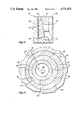
- FIG. 1 is a partial vertical sectional view illustrating a wellhead assembly constructed in accordance with this invention, and showing the seal prior to actuation.
- FIG. 2 is an enlarged partial sectional view of the seal ring of the wellhead assembly of FIG. 1.
- FIG. 3 is a partial sectional view of the wellhead assembly of FIG. 1, taken along the line III-III of FIG. 1.
- FIG. 4 is a partial vertical sectional view of the wellhead assembly of FIG. 1, and showing the seal actuated.
- FIG. 5 is a partial vertical sectional view of an alternate embodiment of a wellhead assembly constructed in accordance with this invention.
- the wellhead assembly includes a lower wellhead housing 11.
- Lower wellhead housing 11 is a tubular member, having an axial bore 13.
- a landing shoulder 15 is located in the bore 13.
- An external flange 17 is located on the upper end of the lower wellhead housing 11.
- a metal seal 19 is located on the upper end of the flange 17.
- a string of casing 21 extends through the lower wellhead housing 11.
- Casing 21 is supported on the lower wellhead housing 11 by a casing hanger 23.
- casing hanger 23 is conventional and is installed after the casing 21 has been cemented. It includes a landing ring 25 that lands on the landing shoulder 15.
- the casing hanger 23 includes a wedge ring 27 located above the landing ring 25.
- a plurality of slips 29 are carried by the wedge ring 27. The slips 29 are pushed inward by the inclined surfaces located between the wedge ring 27 and the slips 29. This causes teeth on the slips 29 to bite into the casing 21 and provide support.
- test ring 31 of conventional design is located in the bore 13 above the hanger 23.
- the test ring 31 has a passage 32 extending between the inner and outer walls of the test ring 31.
- Test ring 31 is sealed between the bore 13 and the casing 21 by elastomeric seals 34.
- An upper wellhead housing 33 lands on the lower wellhead housing 11.
- Upper wellhead housing 33 has an axial bore 35 that is coaxial with the bore 13 of the lower wellhead housing 11.
- the upper wellhead housing 33 has a downward facing shoulder 37 located in the bore 35.
- a flange 39 is formed on the lower end of the upper wellhead housing 33 for connection to the flange 17 of the lower wellhead housing 11.
- the flanges 17, 39 and bolts (not shown) serve as means for connecting the upper wellhead housing 33 to the lower wellhead housing 11.
- a passage (not shown) extends from the exterior to the passage 32 in the test ring for test purposes.
- a seal ring 41 is located in the upper wellhead housing bore 35 above the test ring 31.
- the seal ring 41 has an inner wall 43 that is cylindrical.
- a plurality of annular protrusions or bands 45 protrude inward from the inner wall 43.
- the bands 45 are spaced apart from each other and protrude inward only a slight distance, about 0.040 inch.
- Each band 45 has frusto-conical upper and lower surfaces, and a cylindrical inner diameter or crest.
- the seal ring 41 is solid and is constructed of metal, preferably steel. Also, preferably, the steel is softer than the steel of the casing 21. Typical casing may have a yield strength of 55 to 60,000 psi. Preferably, the yield strength of the seal ring 41 will be about half of the yield strength of the casing 21. This results in the bands 45 deforming permanently when the seal ring 41 is actuated.
- seal ring 41 has an outer wall 47 that is frusto-conical. It inclines from a smaller diameter on the upper end to a larger diameter on its lower end.
- the lower edge 49 of seal ring 41 is also a frusto-conical surface. It tapers downward from the outer wall 47 to the inner wall 43.
- the seal ring 41 has a centerline which coincides with the centerline or axis 51 of the casing 21.
- the axis 51 frequently will be offset a slight distance from the axis 53 of the upper wellhead housing bore 35.
- the casing axis 51 is shown offset to the left from the bore axis 53.
- FIG. 3 is exaggerated greatly, as the amount of offset will normally be less than 0.100 inch.
- the seal ring 41 is formed eccentric.
- the outer wall 47 is truly conical, but its axis or centerline 55 is offset from the centerline of the inner wall 43, which coincides with axis 51 of casing 21. This results in the radial thickness of the seal ring 41 varying.
- the seal ring 41 will have a point 57 of mimimum thickness. A point 59 of maximum thickness will be located 180 degrees from the point 57.
- the amount of offset between the centerline of the inner wall 43 and the centerline 55 of the outer wall 47 is preferably 0.050 inch.
- Wedge ring 61 has a conical inner wall portion 63.
- the inner wall portion 63 extends downward from a cylindrical inner wall portion 65.
- the cylindrical inner wall portion 65 is sufficiently greater in diameter than the outer diameter of the casing 21 to accommodate normal misalignment.
- the cylindrical inner wall portion 65 does not form a sealing function and is also larger in diameter than the inner wall 43 (FIG. 2) of the seal ring 41.
- the wedge ring 61 has an outer wall 67 that is conical and which is adapted to seal against the upper wellhead housing bore 35.
- the degree of taper of the conical outer wall 67 is less than the degree of taper of the inner wall 63.
- the degree of taper of the outer wall 67 is the same as a conical portion provided in the bore 35 of the upper wellhead housing 33.
- One or more sealing bands are located on the outer wall 67 for sealing against the bore 35.
- Wedge ring 61 is not significantly softer than the upper wellhead housing 33 and the bands do not deform.
- the wedge ring 61 is also formed eccentric.
- the centerline for the inner wall portion 63 will be offset from the centerline for the outer wall 67.
- the amount of offset is also about 0.050 inch. This results in a variance in iadial thickness.
- the minimum thickness point 69 will be located 180 degrees from a maxiumum thickness point 71.
- the centerline for the inner wall portion 63 will coincide with the centerline 55 for the seal ring outer wall 47.
- the seal ring 41 and wedge ring 61 are rotatable relative to each other and to the casing 21 to position the centerline for the outer wall portion 67 in alignment with the upper wellhead bore axis 53.
- a drive ring 73 is located between the wedge ring 61 and the shoulder 37 of the upper wellhead housing 33.
- the casing hanger 23 is mounted in the lower wellhead housing 11 to support the casing 21 after the casing 21 has been cemented in place.
- the test ring 31 will be positioned in place.
- the upper end of the casing 21 will be cut off a selected distance above the lower wellhead housing 11.
- the exterior of the casing 21 above the test ring 31 is wire brushed and smoothed with emery cloth.
- the axis 51 (FIG. 3) of the casing 21 is measured relative to the axis of the lower wellhead housing bore 13 to determine any misalignment.
- the axis 53 of the upper wellhead housing 33 will always be in alignment with the axis of the lower wellhead housing bore 13.
- the seal ring 41 and the wedge ring 61 are placed over the casing 21. Both rings 41 and 61 may be rotated, but normally only one of the rings 41, 61 will be rotated. Rotation is performed until the centerline of the outer wall portion 67 of the wedge ring 61 coincides with the bore axis 53. Markings will be located on the wedge ring 61 and the seal ring 41 to indicate the extent of rotation relative to each other.
- the point of maximum eccentricity is shown in FIG. 3, with the minimum points 57, 69 aligned with each other. Zero eccentricity results when one of the rings 41, 61 is rotated 180 degrees from the position shown in FIG. 3. In that case, the casing centerline 51 and axis 53 coincide, indicating no misalignment.
- each ring 41, 61 cancels each other in such a case. If one ring 41, 61 is rotated 90 degrees from the position shown in FIG. 3, the offset of the casing centerline 51 with the bore axis 53 will be one-half the maximum, or 0.050 inch.
- the eccentric offset of the seal ring 41 and the wedge ring 61 will enable the rings 41, 61 to be properly positioned as long as the misalignment of the casing centerline 51 with the bore axis 53 does not exceed 0.100 inch. This allows the centerline of the outer wall 67 of the wedge ring 61 to align perfectly with the bore 35.
- the upper wellhead housing 33 is bolted to the lower wellhead housing 11.
- the upper wellhead housing shoulder 37 bears down on the drive ring 73, which in turn pushes downward on the wedge ring 61.
- the wedge ring 61 pushes the seal ring 41 inward with great force.
- This deformation seals any pits or scratches in the casing 21 while also mating in a gas tight seal.
- the outer wall 67 of the wedge ring 61 forms a tight metal seal with the bore 35.
- the wedge ring 61 in normal cases will not deform.
- the actuated position is shown in FIG. 4.
- the upper wellhead housing 33 may be removed, along with the seal ring 41 at a later date.
- a replacement seal may be used. Because of the softness of the seal ring 41 relative to the casing 21, there will be no need to machine the casing 21 when replacing the seal ring 41. No damage to the casing 21 will occur as a result of the actuation of the seal ring 41.
- the wedge ring 61' is integrally formed to the top of the test ring 31'. Similarly, it has a conical outer wall portion 67' and a conical inner wall 63'.
- the conical inner wall 63' tapers upwardly to a larger diameter on the upper end than on the lower end.
- the wedge ring 61' is inverted from the wedge ring 61 shown in FIGS. 1-4.
- the centerline (not shown) of the inner wall 63' will be offset from the centerline of the outer wall 67'.
- the seal ring 41' also is inverted. It has a cylindrical inner wall 43' and a conical outer wall 47'.
- the conical outer wall 47' tapers downward from a larger diameter on the upper end than on the lower end.
- the drive ring 73' moves the seal ring 41' downward during actuation. This differs from the first emodiment in that the wedge ring 61 is moved by the drive ring 73, rather than the seal ring 41. In other respects, the embodiment in FIG. 5 operates in the same manner. Rotation of the wedge ring 61' is handled by rotating the entire test ring 31'. The rings 41', 61' are rotated until the centerline of the outer wall 67' coincides with the axis of the upper wellhead housing 33'.
- the invention has significant advantages.
- the eccentric wedge and seal rings allow a metal seal to be made easily between casing and a wellhead even though the casing is misaligned with the wellhead.
- the softness of the seal ring relative to the casing provides a tight seal even if minor imperfections in the surface of the casing exists.
- the softness also avoids marring the surface of the casing. This allows the seal to be replaced at a later date without refinishing needing to be done on the casing.
- the invention avoids the need for field machining of the casing.
Abstract
Description
Claims (5)
Priority Applications (4)
| Application Number | Priority Date | Filing Date | Title |
|---|---|---|---|
| US07/130,757 US4771832A (en) | 1987-12-09 | 1987-12-09 | Wellhead with eccentric casing seal ring |
| CA000575403A CA1285217C (en) | 1987-12-09 | 1988-08-23 | Wellhead with eccentric casing seal ring |
| GB8828315A GB2213515B (en) | 1987-12-09 | 1988-12-05 | Wellhead with eccentric casing seal ring |
| MX014118A MX166274B (en) | 1987-12-09 | 1988-12-09 | WELL HEAD WITH ECCENTRIC SEALING RING FOR ADEME |
Applications Claiming Priority (1)
| Application Number | Priority Date | Filing Date | Title |
|---|---|---|---|
| US07/130,757 US4771832A (en) | 1987-12-09 | 1987-12-09 | Wellhead with eccentric casing seal ring |
Publications (1)
| Publication Number | Publication Date |
|---|---|
| US4771832A true US4771832A (en) | 1988-09-20 |
Family
ID=22446178
Family Applications (1)
| Application Number | Title | Priority Date | Filing Date |
|---|---|---|---|
| US07/130,757 Expired - Lifetime US4771832A (en) | 1987-12-09 | 1987-12-09 | Wellhead with eccentric casing seal ring |
Country Status (4)
| Country | Link |
|---|---|
| US (1) | US4771832A (en) |
| CA (1) | CA1285217C (en) |
| GB (1) | GB2213515B (en) |
| MX (1) | MX166274B (en) |
Cited By (38)
| Publication number | Priority date | Publication date | Assignee | Title |
|---|---|---|---|---|
| US4911245A (en) * | 1989-03-10 | 1990-03-27 | Vetco Gray Inc. | Metal seal with soft inlays |
| US5020591A (en) * | 1989-09-11 | 1991-06-04 | Shore James B | Oil tool coupling device |
| US5067734A (en) * | 1990-06-01 | 1991-11-26 | Abb Vetco Gray Inc. | Metal seal with grooved inlays |
| US5090496A (en) * | 1989-06-28 | 1992-02-25 | Baroid Technology, Inc. | Down-hole bent motor housings |
| US5110144A (en) * | 1990-08-24 | 1992-05-05 | Cooper Industries, Inc. | Casing hanger seal assembly |
| US5129660A (en) * | 1991-02-25 | 1992-07-14 | Cooper Industries, Inc. | Seal assembly for a well housing hanger structure |
| US5174376A (en) * | 1990-12-21 | 1992-12-29 | Fmc Corporation | Metal-to-metal annulus packoff for a subsea wellhead system |
| US5193616A (en) * | 1991-08-06 | 1993-03-16 | Cooper Industries, Inc. | Tubing hanger seal assembly |
| US5257792A (en) * | 1991-10-15 | 1993-11-02 | Fip Incorporated | Well head metal seal |
| US5464063A (en) * | 1994-08-19 | 1995-11-07 | Abb Vetco Gray Inc. | Well assembly metal seal |
| US5755287A (en) * | 1996-04-03 | 1998-05-26 | Fmc Corporation | Sealing assembly for subsea wellheads |
| US5792492A (en) * | 1996-07-05 | 1998-08-11 | Seikoh Giken Co., Ltd. | Optical disk molding apparatus equipped with liquid sealing means |
| US6032958A (en) * | 1998-03-31 | 2000-03-07 | Hydril Company | Bi-directional pressure-energized metal seal |
| WO2001063161A1 (en) * | 2000-02-23 | 2001-08-30 | Plexus Ocean Systems Limited | Pipe joint |
| US6705615B2 (en) | 2001-10-31 | 2004-03-16 | Dril-Quip, Inc. | Sealing system and method |
| US20050082829A1 (en) * | 2003-10-17 | 2005-04-21 | Dallas L. M. | Metal ring gasket for a threaded union |
| US7111688B2 (en) | 1998-10-26 | 2006-09-26 | Plexus Ocean Systems, Ltd. | Clamping well casings |
| US20070013188A1 (en) * | 2005-07-14 | 2007-01-18 | Hwces International | High-pressure threaded union with metal-to-metal seal, and metal ring gasket for same |
| US20090133884A1 (en) * | 2007-11-27 | 2009-05-28 | Fenton Stephen P | Pressure energized seal |
| US20100007097A1 (en) * | 2008-07-08 | 2010-01-14 | Worldwide Oilfield Machine, Inc. | Resilient High Pressure Metal-to-Metal Seal and Method |
| US20110186302A1 (en) * | 2009-12-23 | 2011-08-04 | Bp Corporation North America Inc. | Rigless low volume pump system |
| US20110278023A1 (en) * | 2010-05-13 | 2011-11-17 | Randy Lewkoski | Assembly for controlling annuli between tubulars |
| US20120034113A1 (en) * | 2010-08-05 | 2012-02-09 | Hydro Leduc | Pumping device for fluids located at the bottom of a drilled well |
| CN102777602A (en) * | 2012-08-02 | 2012-11-14 | 昆山旭虹精密零组件有限公司 | Sealing ring used for petroleum machinery |
| RU2481170C2 (en) * | 2011-08-09 | 2013-05-10 | Федеральное государственное унитарное предприятие "Государственный космический научно-производственный центр имени М.В. Хруничева" (ФГУП "ГКНПЦ им. М.В. Хруничева") | Large size section lower die for explosive correction |
| US8960276B2 (en) | 2010-09-22 | 2015-02-24 | Stream-Flo Industries Ltd. | Wellhead seal device to seal casing |
| US9273655B2 (en) * | 2012-09-21 | 2016-03-01 | Nok Corporation | Sealing device |
| WO2016144536A1 (en) * | 2015-03-11 | 2016-09-15 | Cameron International Corporation | Multi-metal seal system |
| WO2017007817A1 (en) * | 2015-07-06 | 2017-01-12 | Ge Oil & Gas Pressure Control Lp | Offset adjustment rings for wellhead orientation |
| US20170074434A1 (en) * | 2014-03-31 | 2017-03-16 | Fmc Technologies, Inc. | Connector with actuatable reaction members to resist bending loads |
| US20180010409A1 (en) * | 2016-07-08 | 2018-01-11 | Ge Oil & Gas Pressure Control Lp | Electrically insulated tubing hanger system |
| US10030490B2 (en) | 2014-04-16 | 2018-07-24 | Bp Corporation North America, Inc. | Reciprocating pumps for downhole deliquification systems and fluid distribution systems for actuating reciprocating pumps |
| CN110359860A (en) * | 2019-08-21 | 2019-10-22 | 中国石油集团渤海钻探工程有限公司第一固井分公司 | Cementing head clamping hoop type ready-packaged joint and application method |
| US11111749B2 (en) | 2019-05-14 | 2021-09-07 | Saudi Arabian Oil Company | Correcting offsets in wellbore tubulars |
| US11193353B2 (en) | 2012-10-04 | 2021-12-07 | Halliburton Energy Services, Inc. | Sliding sleeve well tool with metal-to-metal seal |
| US11319756B2 (en) | 2020-08-19 | 2022-05-03 | Saudi Arabian Oil Company | Hybrid reamer and stabilizer |
| US20230212922A1 (en) * | 2022-01-04 | 2023-07-06 | Vault Pressure Control, Llc | Wellhead attachment system |
| CN110359860B (en) * | 2019-08-21 | 2024-04-26 | 中国石油集团渤海钻探工程有限公司第一固井分公司 | Cement head clamp type quick-mounting connector and use method thereof |
Citations (13)
| Publication number | Priority date | Publication date | Assignee | Title |
|---|---|---|---|---|
| US1323660A (en) * | 1919-12-02 | Well-capping device | ||
| US1548543A (en) * | 1922-04-17 | 1925-08-04 | Joseph F Moody | Well equipment |
| US2179814A (en) * | 1938-05-25 | 1939-11-14 | Billy F Conaghan | Adjustable tubing hanger and stuffing box support |
| US3895831A (en) * | 1973-05-10 | 1975-07-22 | Conax Corp | Seal assembly providing dual seal zones |
| US3899200A (en) * | 1973-01-05 | 1975-08-12 | Scovill Manufacturing Co | Fluid conduits |
| US4131287A (en) * | 1977-07-11 | 1978-12-26 | Exxon Production Research Company | Annular seal |
| US4390186A (en) * | 1982-02-04 | 1983-06-28 | Combustion Engineering, Inc. | Metal-to-metal ribbed seal |
| US4556224A (en) * | 1984-08-06 | 1985-12-03 | Joy Manufacturing Company | Crossover seal assembly |
| US4569540A (en) * | 1983-12-29 | 1986-02-11 | Beson Technology, Inc. | Piping suspender with metal-to-metal seal |
| US4646845A (en) * | 1984-08-14 | 1987-03-03 | Cactus Wellhead Equipment Co., Inc. | Metal seal for wellhead apparatus |
| US4650225A (en) * | 1986-03-31 | 1987-03-17 | Joy Manufacturing Company | Hydraulic holddown screw with mechanical retention means |
| US4650226A (en) * | 1986-03-31 | 1987-03-17 | Joy Manufacturing Company | Holddown screw |
| US4678209A (en) * | 1985-10-21 | 1987-07-07 | Vetco Offshore, Inc. | Casing hanger |
-
1987
- 1987-12-09 US US07/130,757 patent/US4771832A/en not_active Expired - Lifetime
-
1988
- 1988-08-23 CA CA000575403A patent/CA1285217C/en not_active Expired - Lifetime
- 1988-12-05 GB GB8828315A patent/GB2213515B/en not_active Expired
- 1988-12-09 MX MX014118A patent/MX166274B/en unknown
Patent Citations (13)
| Publication number | Priority date | Publication date | Assignee | Title |
|---|---|---|---|---|
| US1323660A (en) * | 1919-12-02 | Well-capping device | ||
| US1548543A (en) * | 1922-04-17 | 1925-08-04 | Joseph F Moody | Well equipment |
| US2179814A (en) * | 1938-05-25 | 1939-11-14 | Billy F Conaghan | Adjustable tubing hanger and stuffing box support |
| US3899200A (en) * | 1973-01-05 | 1975-08-12 | Scovill Manufacturing Co | Fluid conduits |
| US3895831A (en) * | 1973-05-10 | 1975-07-22 | Conax Corp | Seal assembly providing dual seal zones |
| US4131287A (en) * | 1977-07-11 | 1978-12-26 | Exxon Production Research Company | Annular seal |
| US4390186A (en) * | 1982-02-04 | 1983-06-28 | Combustion Engineering, Inc. | Metal-to-metal ribbed seal |
| US4569540A (en) * | 1983-12-29 | 1986-02-11 | Beson Technology, Inc. | Piping suspender with metal-to-metal seal |
| US4556224A (en) * | 1984-08-06 | 1985-12-03 | Joy Manufacturing Company | Crossover seal assembly |
| US4646845A (en) * | 1984-08-14 | 1987-03-03 | Cactus Wellhead Equipment Co., Inc. | Metal seal for wellhead apparatus |
| US4678209A (en) * | 1985-10-21 | 1987-07-07 | Vetco Offshore, Inc. | Casing hanger |
| US4650225A (en) * | 1986-03-31 | 1987-03-17 | Joy Manufacturing Company | Hydraulic holddown screw with mechanical retention means |
| US4650226A (en) * | 1986-03-31 | 1987-03-17 | Joy Manufacturing Company | Holddown screw |
Cited By (64)
| Publication number | Priority date | Publication date | Assignee | Title |
|---|---|---|---|---|
| US4911245A (en) * | 1989-03-10 | 1990-03-27 | Vetco Gray Inc. | Metal seal with soft inlays |
| US5090496A (en) * | 1989-06-28 | 1992-02-25 | Baroid Technology, Inc. | Down-hole bent motor housings |
| US5020591A (en) * | 1989-09-11 | 1991-06-04 | Shore James B | Oil tool coupling device |
| US5067734A (en) * | 1990-06-01 | 1991-11-26 | Abb Vetco Gray Inc. | Metal seal with grooved inlays |
| US5110144A (en) * | 1990-08-24 | 1992-05-05 | Cooper Industries, Inc. | Casing hanger seal assembly |
| US5174376A (en) * | 1990-12-21 | 1992-12-29 | Fmc Corporation | Metal-to-metal annulus packoff for a subsea wellhead system |
| US5129660A (en) * | 1991-02-25 | 1992-07-14 | Cooper Industries, Inc. | Seal assembly for a well housing hanger structure |
| US5193616A (en) * | 1991-08-06 | 1993-03-16 | Cooper Industries, Inc. | Tubing hanger seal assembly |
| US5257792A (en) * | 1991-10-15 | 1993-11-02 | Fip Incorporated | Well head metal seal |
| US5464063A (en) * | 1994-08-19 | 1995-11-07 | Abb Vetco Gray Inc. | Well assembly metal seal |
| US5755287A (en) * | 1996-04-03 | 1998-05-26 | Fmc Corporation | Sealing assembly for subsea wellheads |
| US5792492A (en) * | 1996-07-05 | 1998-08-11 | Seikoh Giken Co., Ltd. | Optical disk molding apparatus equipped with liquid sealing means |
| US6032958A (en) * | 1998-03-31 | 2000-03-07 | Hydril Company | Bi-directional pressure-energized metal seal |
| US7111688B2 (en) | 1998-10-26 | 2006-09-26 | Plexus Ocean Systems, Ltd. | Clamping well casings |
| WO2001063161A1 (en) * | 2000-02-23 | 2001-08-30 | Plexus Ocean Systems Limited | Pipe joint |
| GB2375152A (en) * | 2000-02-23 | 2002-11-06 | Plexus Ocean Syst Ltd | Pipe joint |
| US20030141718A1 (en) * | 2000-02-23 | 2003-07-31 | Bilderbeek Bernard Herman Van | Pipe joint |
| GB2375152B (en) * | 2000-02-23 | 2003-11-26 | Plexus Ocean Syst Ltd | Pipe joint |
| US7648176B2 (en) * | 2000-02-23 | 2010-01-19 | Plexus Ocean Systems, Ltd. | Pipe joint |
| US7344162B2 (en) | 2000-02-23 | 2008-03-18 | Plexus Ocean Systems Limited | Pipe joint |
| US20080111375A1 (en) * | 2000-02-23 | 2008-05-15 | Bernard Herman Van Bilderbeek | Pipe joint |
| US6705615B2 (en) | 2001-10-31 | 2004-03-16 | Dril-Quip, Inc. | Sealing system and method |
| US20050082829A1 (en) * | 2003-10-17 | 2005-04-21 | Dallas L. M. | Metal ring gasket for a threaded union |
| US7125055B2 (en) * | 2003-10-17 | 2006-10-24 | Oil States Energy Services, Inc. | Metal ring gasket for a threaded union |
| US20110175349A1 (en) * | 2005-07-14 | 2011-07-21 | Stinger Wellhead Protection, Inc. | High-pressure threaded union with metal-to-metal seal, and metal ring gasket for same |
| US20070013188A1 (en) * | 2005-07-14 | 2007-01-18 | Hwces International | High-pressure threaded union with metal-to-metal seal, and metal ring gasket for same |
| US20090091131A1 (en) * | 2005-07-14 | 2009-04-09 | Stinger Wellhead Protection, Inc. | High-pressure threaded union with metal-to-metal seal, and metal ring gasket for same |
| US8205916B2 (en) | 2005-07-14 | 2012-06-26 | Stinger Wellhead Protection, Inc. | High-pressure threaded union with metal-to-metal seal, and metal ring gasket for same |
| US7484776B2 (en) | 2005-07-14 | 2009-02-03 | Stinger Wellhead Protection, Inc. | High-pressure threaded union with metal-to-metal seal, and metal ring gasket for same |
| US7654585B2 (en) | 2005-07-14 | 2010-02-02 | Stinger Wellhead Protection, Inc. | High-pressure threaded union with metal-to-metal seal, and metal ring gasket for same |
| US20100096852A1 (en) * | 2005-07-14 | 2010-04-22 | Stinger Wellhead Protection, Inc. | High-pressure threaded union with metal-to-metal seal, and metal ring gasket for same |
| US7922216B2 (en) | 2005-07-14 | 2011-04-12 | Stinger Wellhead Protection, Inc. | High-pressure threaded union with metal-to-metal seal, and metal ring gasket for same |
| US7740080B2 (en) | 2007-11-27 | 2010-06-22 | Vetco Gray Inc. | Pressure energized seal |
| US20090133884A1 (en) * | 2007-11-27 | 2009-05-28 | Fenton Stephen P | Pressure energized seal |
| US8205890B2 (en) | 2008-07-08 | 2012-06-26 | Worldwide Oilfield Machine, Inc. | Resilient high pressure metal-to-metal seal and method |
| US20100007097A1 (en) * | 2008-07-08 | 2010-01-14 | Worldwide Oilfield Machine, Inc. | Resilient High Pressure Metal-to-Metal Seal and Method |
| US8511390B2 (en) | 2009-12-23 | 2013-08-20 | Bp Corporation North America Inc. | Rigless low volume pump system |
| US20110186302A1 (en) * | 2009-12-23 | 2011-08-04 | Bp Corporation North America Inc. | Rigless low volume pump system |
| US9127535B2 (en) | 2009-12-23 | 2015-09-08 | Bp Corporation North America Inc. | Rigless low volume pump system |
| US8925637B2 (en) | 2009-12-23 | 2015-01-06 | Bp Corporation North America, Inc. | Rigless low volume pump system |
| US20110278023A1 (en) * | 2010-05-13 | 2011-11-17 | Randy Lewkoski | Assembly for controlling annuli between tubulars |
| US8307889B2 (en) * | 2010-05-13 | 2012-11-13 | Randy Lewkoski | Assembly for controlling annuli between tubulars |
| US8834133B2 (en) * | 2010-08-05 | 2014-09-16 | Bp Corporation North America Inc. | Pumping device for fluids located at the bottom of a drilled well |
| US20120034113A1 (en) * | 2010-08-05 | 2012-02-09 | Hydro Leduc | Pumping device for fluids located at the bottom of a drilled well |
| US8960276B2 (en) | 2010-09-22 | 2015-02-24 | Stream-Flo Industries Ltd. | Wellhead seal device to seal casing |
| RU2481170C2 (en) * | 2011-08-09 | 2013-05-10 | Федеральное государственное унитарное предприятие "Государственный космический научно-производственный центр имени М.В. Хруничева" (ФГУП "ГКНПЦ им. М.В. Хруничева") | Large size section lower die for explosive correction |
| CN102777602A (en) * | 2012-08-02 | 2012-11-14 | 昆山旭虹精密零组件有限公司 | Sealing ring used for petroleum machinery |
| US9273655B2 (en) * | 2012-09-21 | 2016-03-01 | Nok Corporation | Sealing device |
| US11193353B2 (en) | 2012-10-04 | 2021-12-07 | Halliburton Energy Services, Inc. | Sliding sleeve well tool with metal-to-metal seal |
| US10082231B2 (en) * | 2014-03-31 | 2018-09-25 | Fmc Technologies, Inc. | Connector with actuatable reaction members to resist bending loads |
| US20170074434A1 (en) * | 2014-03-31 | 2017-03-16 | Fmc Technologies, Inc. | Connector with actuatable reaction members to resist bending loads |
| US10030490B2 (en) | 2014-04-16 | 2018-07-24 | Bp Corporation North America, Inc. | Reciprocating pumps for downhole deliquification systems and fluid distribution systems for actuating reciprocating pumps |
| WO2016144536A1 (en) * | 2015-03-11 | 2016-09-15 | Cameron International Corporation | Multi-metal seal system |
| US10113384B2 (en) * | 2015-03-11 | 2018-10-30 | Cameron International Corporation | Multi-metal seal system |
| US20160265298A1 (en) * | 2015-03-11 | 2016-09-15 | Cameron International Corporation | Multi-metal seal system |
| WO2017007817A1 (en) * | 2015-07-06 | 2017-01-12 | Ge Oil & Gas Pressure Control Lp | Offset adjustment rings for wellhead orientation |
| US10253589B2 (en) | 2015-07-06 | 2019-04-09 | Ge Oil & Gas Pressure Control Lp | Offset adjustment rings for wellhead orientation |
| US20180010409A1 (en) * | 2016-07-08 | 2018-01-11 | Ge Oil & Gas Pressure Control Lp | Electrically insulated tubing hanger system |
| US10605032B2 (en) * | 2016-07-08 | 2020-03-31 | Ge Oil & Gas Pressure Control Lp | Electrically insulated tubing hanger system |
| US11111749B2 (en) | 2019-05-14 | 2021-09-07 | Saudi Arabian Oil Company | Correcting offsets in wellbore tubulars |
| CN110359860A (en) * | 2019-08-21 | 2019-10-22 | 中国石油集团渤海钻探工程有限公司第一固井分公司 | Cementing head clamping hoop type ready-packaged joint and application method |
| CN110359860B (en) * | 2019-08-21 | 2024-04-26 | 中国石油集团渤海钻探工程有限公司第一固井分公司 | Cement head clamp type quick-mounting connector and use method thereof |
| US11319756B2 (en) | 2020-08-19 | 2022-05-03 | Saudi Arabian Oil Company | Hybrid reamer and stabilizer |
| US20230212922A1 (en) * | 2022-01-04 | 2023-07-06 | Vault Pressure Control, Llc | Wellhead attachment system |
Also Published As
| Publication number | Publication date |
|---|---|
| CA1285217C (en) | 1991-06-25 |
| MX166274B (en) | 1992-12-28 |
| GB2213515B (en) | 1991-08-21 |
| GB2213515A (en) | 1989-08-16 |
| GB8828315D0 (en) | 1989-01-05 |
Similar Documents
| Publication | Publication Date | Title |
|---|---|---|
| US4771832A (en) | Wellhead with eccentric casing seal ring | |
| US4949786A (en) | Emergency casing hanger | |
| US8047281B2 (en) | Sleeve for expandable tubular threaded connection and method of expanding tubular thereof | |
| US4911245A (en) | Metal seal with soft inlays | |
| US4390186A (en) | Metal-to-metal ribbed seal | |
| US4595053A (en) | Metal-to-metal seal casing hanger | |
| US5555935A (en) | Fluid connector for well | |
| US5135266A (en) | Casing slips and seal member | |
| US4674569A (en) | Stage cementing tool | |
| AU691876B2 (en) | Fluid-tight connecting apparatus | |
| AU606428B2 (en) | Subsea casing hanger packoff assembly | |
| US5285853A (en) | Casing hanger seal with test port | |
| GB2276647A (en) | Casing hanger seal assembly | |
| US4202410A (en) | Seal testing arrangement for wellheads | |
| US20050248154A1 (en) | Threaded connection for oil field applications | |
| US5725056A (en) | Wellhead assembly with removable bowl adapter | |
| US20030042028A1 (en) | High pressure high temperature packer system | |
| JPS6085188A (en) | Well head seal apparatus | |
| US5094297A (en) | Casing weight set seal ring | |
| US2485940A (en) | Packing cartridge | |
| AU5602199A (en) | Metal-to-metal seal assembly for oil and gas production apparatus | |
| CA1206091A (en) | Breech block hanger support | |
| IE51011B1 (en) | Flanging system for suspending casing and tubing columns for high pressure oil or gas wells | |
| US20230175625A1 (en) | An improved connector for a subsea drilling riser | |
| US5062667A (en) | Connection seal |
Legal Events
| Date | Code | Title | Description |
|---|---|---|---|
| AS | Assignment |
Owner name: VETCO GRAY INC., 7135 ARDMORE ST., P.O. BOX 2291, Free format text: ASSIGNMENT OF ASSIGNORS INTEREST.;ASSIGNOR:BRIDGES, CHARLES D.;REEL/FRAME:004799/0935 Effective date: 19871204 Owner name: VETCO GRAY INC., 7135 ARDMORE ST., P.O. BOX 2291, Free format text: ASSIGNMENT OF ASSIGNORS INTEREST;ASSIGNOR:BRIDGES, CHARLES D.;REEL/FRAME:004799/0935 Effective date: 19871204 |
|
| STCF | Information on status: patent grant |
Free format text: PATENTED CASE |
|
| CC | Certificate of correction | ||
| AS | Assignment |
Owner name: CITIBANK, N.A., AS AGENT Free format text: SECURITY INTEREST;ASSIGNOR:VETCO GRAY INC.;REEL/FRAME:005211/0237 Effective date: 19891128 |
|
| FPAY | Fee payment |
Year of fee payment: 4 |
|
| FEPP | Fee payment procedure |
Free format text: PAYOR NUMBER ASSIGNED (ORIGINAL EVENT CODE: ASPN); ENTITY STATUS OF PATENT OWNER: LARGE ENTITY |
|
| FPAY | Fee payment |
Year of fee payment: 8 |
|
| FPAY | Fee payment |
Year of fee payment: 12 |
|
| AS | Assignment |
Owner name: VETCO GRAY, INC., TEXAS Free format text: RELEASE BY SECURED PARTY;ASSIGNOR:CITIBANK, N.A.;REEL/FRAME:014953/0392 Effective date: 19910502 |