US4772093A - Fiber-optic image-carrying device - Google Patents
Fiber-optic image-carrying device Download PDFInfo
- Publication number
- US4772093A US4772093A US06/917,915 US91791586A US4772093A US 4772093 A US4772093 A US 4772093A US 91791586 A US91791586 A US 91791586A US 4772093 A US4772093 A US 4772093A
- Authority
- US
- United States
- Prior art keywords
- image
- micro
- diameter
- fibers
- fused
- Prior art date
- Legal status (The legal status is an assumption and is not a legal conclusion. Google has not performed a legal analysis and makes no representation as to the accuracy of the status listed.)
- Expired - Lifetime
Links
Images


Classifications
-
- G—PHYSICS
- G02—OPTICS
- G02B—OPTICAL ELEMENTS, SYSTEMS OR APPARATUS
- G02B23/00—Telescopes, e.g. binoculars; Periscopes; Instruments for viewing the inside of hollow bodies; Viewfinders; Optical aiming or sighting devices
- G02B23/24—Instruments or systems for viewing the inside of hollow bodies, e.g. fibrescopes
- G02B23/26—Instruments or systems for viewing the inside of hollow bodies, e.g. fibrescopes using light guides
-
- A—HUMAN NECESSITIES
- A61—MEDICAL OR VETERINARY SCIENCE; HYGIENE
- A61B—DIAGNOSIS; SURGERY; IDENTIFICATION
- A61B1/00—Instruments for performing medical examinations of the interior of cavities or tubes of the body by visual or photographical inspection, e.g. endoscopes; Illuminating arrangements therefor
- A61B1/00064—Constructional details of the endoscope body
- A61B1/00071—Insertion part of the endoscope body
- A61B1/0008—Insertion part of the endoscope body characterised by distal tip features
- A61B1/00096—Optical elements
-
- A—HUMAN NECESSITIES
- A61—MEDICAL OR VETERINARY SCIENCE; HYGIENE
- A61B—DIAGNOSIS; SURGERY; IDENTIFICATION
- A61B1/00—Instruments for performing medical examinations of the interior of cavities or tubes of the body by visual or photographical inspection, e.g. endoscopes; Illuminating arrangements therefor
- A61B1/00064—Constructional details of the endoscope body
- A61B1/00071—Insertion part of the endoscope body
- A61B1/0008—Insertion part of the endoscope body characterised by distal tip features
- A61B1/00101—Insertion part of the endoscope body characterised by distal tip features the distal tip features being detachable
-
- A—HUMAN NECESSITIES
- A61—MEDICAL OR VETERINARY SCIENCE; HYGIENE
- A61B—DIAGNOSIS; SURGERY; IDENTIFICATION
- A61B1/00—Instruments for performing medical examinations of the interior of cavities or tubes of the body by visual or photographical inspection, e.g. endoscopes; Illuminating arrangements therefor
- A61B1/00064—Constructional details of the endoscope body
- A61B1/0011—Manufacturing of endoscope parts
-
- A—HUMAN NECESSITIES
- A61—MEDICAL OR VETERINARY SCIENCE; HYGIENE
- A61B—DIAGNOSIS; SURGERY; IDENTIFICATION
- A61B1/00—Instruments for performing medical examinations of the interior of cavities or tubes of the body by visual or photographical inspection, e.g. endoscopes; Illuminating arrangements therefor
- A61B1/00163—Optical arrangements
- A61B1/00165—Optical arrangements with light-conductive means, e.g. fibre optics
- A61B1/00167—Details of optical fibre bundles, e.g. shape or fibre distribution
-
- Y—GENERAL TAGGING OF NEW TECHNOLOGICAL DEVELOPMENTS; GENERAL TAGGING OF CROSS-SECTIONAL TECHNOLOGIES SPANNING OVER SEVERAL SECTIONS OF THE IPC; TECHNICAL SUBJECTS COVERED BY FORMER USPC CROSS-REFERENCE ART COLLECTIONS [XRACs] AND DIGESTS
- Y10—TECHNICAL SUBJECTS COVERED BY FORMER USPC
- Y10S—TECHNICAL SUBJECTS COVERED BY FORMER USPC CROSS-REFERENCE ART COLLECTIONS [XRACs] AND DIGESTS
- Y10S600/00—Surgery
- Y10S600/92—Method of making endoscopes
Definitions
- This invention relates to fiber-optic image-carrying devices for examining regions that are remote or difficult of access.
- an image-carrying unit that is very small (e.g., with outside diameter less than 1 mm and preferably about 0.5 mm or less), which is practical to make and which has useful image size, field of view and degree of contrast. It is also desirable to achieve a catheter which combines a flexible image-carrying unit, a means for delivering illumination to the viewing area and a working channel, in an overall assembly that likewise is very small, e.g., less than 3 mm overall diameter.
- the micro-unit is comprised of the order of two thousand fibers in the coherent array; the outer surface of the micro-unit comprises an encapsulating glass sleeve intimately drawn and fused with the coherent array of fibers; the protective polymeric portion comprises a thermoplastic coating; the member has a characteristic bend radius in the range between about 1 and 6 centimeters, preferably at least at its distal region the bend radius being about 2 centimeters or less; the protective polymeric portion comprises a relatively opaque layer that surrounds the multi-fiber unit, preferably this layer having a thickness of the order of about 0.001 inch and is in a UV-cured state; a transparent layer overlies the relatively opaque layer, the transparent layer having a substantially greater thickness than the relatively opaque layer, and where the transparent layer comprises a substantial thickness of clear material that creates a potential transmission cross-section, the relatively opaque layer, by serving to absorb light that is moving with lateral component toward the multi-fiber unit, prevents the light from being transmitted by wave-guide effect
- such an image-carrying member is incorporated within a flexible catheter which also has an illumination light guide means extending through a lumen of the catheter.
- the image-carrying member and the light guide means are contained in separate lumens of the catheter; another lumen provides an open working channel at least as large as the lumen containing the image-carrying member;
- the catheter has an outer diameter of about 3 mm or less, preferably an outer diameter of the order of 2 mm;
- the catheter has, at its proximal end, a connector adapted to detachably connect the image-carrying member to a handle which has an associated ocular means and light source means, whereby the catheter can be replaced without replacement of the handle;
- the components provide an improved image attributable to pin-hole optics principles that partially compensate for aberration produced by the spherical
- the image-carrying member is comprised of a coherent array of a large multiplicity of optical fibers
- the coherent array of fibers of the image-carrying member comprises, as mentioned above, a drawn and fused micro-unit in which there are of the order of two thousand constituent fibers that are fused to each other, the microunit having a bend radius of 6 centimeters or less.
- the lens has a diameter of about 0.020 inch, the diameter of the lens being no greater than about 120% of the diameter of the image-carrying member.
- a method of examination of small ducts and vessels of a body comprising introducing into such a passage the remote vision micro-optical member as described above, and, while moving the micro-optical member axially in the passage, observing the relationship of the change in position of the instrument in the body with respect to the zoomed change of the image of an area of interest along the wall of the small passage.
- an examination device comprises a hollow metal tube adapted to be inserted into a body, the tube containing and supporting a remote vision micro-optical member as described above, with the lens located in the distal portion of the tube.
- a vision system includes the image-carrying micro-optical member described above and a handle to which it is adapted to be connected via a connector, the connector comprising a male member having an accurately machined surface of revolution adapted to interfit with a corresponding female receptacle of the handle, the axis of the micro-unit lying on the axis of the surface of revolution of the connector and the axis of the optics of the handle aligned with the axis of the female receptacle, the end of the male member having a step to one side of the axis adapted to interfit with a step provided within the female receptacle.
- two axially spaced apart end surfaces are associated with the step, an interface between the image-carrying micro-unit and a further image-carrying member in the handle being located at one of the end surfaces, and an interface between a light source and a light guide for transmitting illumination to the object to be observed by the lens being located at the other of the spaced apart end surfaces.
- a connector system for connecting an image-carrying member as described above with a handle having associated optics, comprising a male connector associated with the image-carrying member and having an accurately machined surface of revolution adapted to interfit with a corresponding female receptacle of the handle, the axis of the member lying on the axis of the surface of revolution of the connector and the axis of the optics of the handle aligned with the axis of the female receptacle, the end of the male member having a step to one side of the axis adapted to interfit with a step provided within the female receptacle, a light guide terminating upon the step of the male member and being aligned with a light delivery source within the handle.
- a flexible fiberoptic probe useful for the examination of small ducts and passages comprises: an eyepiece, a distal lens means and the remote vision micro-optical member as described above, having of the order of 2,000 coherently arranged fibers, the member extending between the eyepiece and the distal lens means, the distal lens means having a diameter of the order of that of the member and selected to provide a wide angle view in air of about 80° or greater, neutral magnification at a distance selected in the range of 4 to 8 mm and increasing magnification at closer distances down to at least 2 mm.
- a method of forming the remote vision mico-optical member described above comprises fusing and drawing a multi-fiber micro-unit having about 2,000 clad glass fibers, to form a fused unit having fibers of the order of 8 micron diameter, coating the surface of the micro-unit substantially immediately after drawing with a protective coating, and, during the drawing, maintaining the balance of the physical properties of the glass and the drawing temperature and rate to provide substantially uniform tension throughout the formed micro-unit.
- a method for forming the remote vision member in a manner to provide relatively greater flexibility in a distal portion comprises further drawing the distal portion to smaller diameter; or leaching a limited distal portion to remove at least a portion of the cladding about the fibers.
- a multi-fiber micro-unit that may be employed in a micro-optical system to achieve microendoscopy. Due to its flexibility, the unit may be used in flexible as well as rigid imaging-probes. Combined in a micro-optical system with a correspondingly small optical quality spherical lens and closure window, the multi-fiber unit provides a desirable image, with resolution down to about 0.001 inch and an ability to view over an angle of about 80° in air, a distinct advantage in examination of side walls of very narrow passages.
- the invention also provides a system for detachably connecting the imaging probe containing the micro-optical system with a viewing handpiece containing an ocular system and illumination light source connections that achieves precise alignment of image and illumination components.
- FIG. 1 is a diagrammatic representation of a process for forming an image unit of the invention
- FIG. 1a is a representation of another process for forming an image unit
- FIG. 2 is an enlarged side section view of a coating cup
- FIG. 3 is a longitudinal cross-section of a fused fiber-optic unit made according to the invention.
- FIG. 4 shows a needle probe image-carrying inspection device according to the invention while FIG. 4a is a much enlarged end view thereof;
- FIG. 5 shows a flexible catheter inspection device according to the invention, while FIG. 5a is an end view of the catheter and FIG. 5b is a much enlarged sectional view of a portion of FIG. 5a containing its fused image unit;
- FIG. 6 is a side view of one embodiment of an elongated imaging probe of the invention with the thickness of the probe exaggerated in size for purpose of illustration;
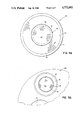
- FIG. 7 is a side section view of the distal portion of the imaging probe of FIG. 6, while FIG. 7a is an end view taken on line 7a--7a of FIG. 7;
- FIG. 8 is an enlarged side section view of the proximal connector of FIG. 6, while FIG. 8a is an end view taken on line 8a--8a of FIG. 8;
- FIG. 9 is a side section view of a viewing handpiece for use with the probe of FIG. 6-8;
- FIG. 10 is a plan view of the proximal portion of another probe embodiment of the invention, while FIG. 10a is a transverse section view taken on line 10a--10a of FIG. 10;
- FIGS. 11 and 12 are somewhat diagrammatic side views of other embodiments of the distal ends of imaging probes of the invention.
- FIG. 13 is a side section view of the distal end portion of another embodiment of an image-carrying probe member, while FIG. 14 is a similar view of the proximal connector thereof;
- FIG. 15 is a diagrammatic view of an embodiment of the probe of the invention having varying flexibility, with a highly flexible distal end;
- FIGS. 16 and 17 are somewhat diagrammatic side views of the distal end portion of embodiments of image units that enable the realization of the image-carrying member of FIG. 15.
- a very large number (typically of the order of 2,000, e.g., 1,800) of individual glass optical fibers, each about 0.25 mm or more in diameter and consisting of a core surrounded by a cladding material of relatively lower index of refraction, are assembled in coherent array within a bundle 10 and placed within a glass stuffer tube 12 to comprise preform 14.
- Tube 12 has an outer diameter of about 40 mm and its material is selected to be at least compatible with and preferably to be the same as the cladding of the individual fibers.
- the core, cladding and stuffer tube are all of borosilicate glass.
- the clad thickness can be quite thin, allowing high packing and hence good contrast resolution to be achieved in the micro-unit being formed.
- the numerical aperture of glass enables transmission of a wide angle image, which is of particular importance in examining the walls of tiny ducts of the body.
- the preform assembly 14 is fed through a heating furnace 18.
- the preform, including the fibers, is heated to the softening point, in softening zone 20, and is then drawn as a unit to decrease the outer diameter to the desired micro-unit dimension, e.g., to about 0.5 to 1.0 mm (0.020 to 0.040 inch), or less.
- substantially constant tension can be maintained throughout the length of the formed micro-unit, a condition found to be very desirable for achieving a high yield rate of satisfactory units.
- the drawing action fuses the tiny fibers to one another and fuses the encapsulating layer to the surrounded optical fibers in a uniform way so that the resulting image unit is compact, presents a relatively large active image area for its overall size, and is flexible due to its small bend cross-section.
- the drawn multi-fiber unit is immediately passed through coating cup 22 containing the relatively opaque coating material 24 that carries an opaque constituent, described in detail below, so that the pristine, as-drawn surface of the glass is immediately protected. Referring also to FIG.
- the base 26 of the coating cup is in the form of a nozzle 28 defining a narrow aperture 30 of length, L, and diameter, D, selected as described in Panoliaskos, Hallet, and Garis, "Prediction of Optical Fiber Coating Thickness", Applied Optics, 24 (15): 2309-2312, Aug., 1985, which is incorporated herein by reference.
- This cup allows through-passage of the optical fiber bundle and applies a predetermined thickness of coating material 24 about the encapsulating layer, e.g., a thickness between about 0.0005 to 0.002 inch.
- the pristine surface of the drawn unit is immediately protected against moisture, pollutants, etc. in the air to prevent microcracking and the flexibility of the unit is preserved.
- the relatively opaquely coated optical fiber assembly 32' is directly fed to a second coating cup 34 containing a clear protective coating material 36 of a relative viscosity lower than that of the relatively opaque coating material 24, e.g., to prevent mixing of the material of the two layers.
- the nozzle 38 of coating cup 34 is also sized and dimensioned for through-passage of the coated fiber assembly 32" with the desired thickness of clear protective coating material, e.g. 0.010 inch.
- a coated optical fiber assembly 32 e.g., for use in a rigid needle probe or where the second transparent layer is not required, is passed through only a single cup 22a to apply the relatively opaque layer.
- the coated assembly (32', FIG. 1a; 32", FIG. 1) is then cured by passage through ultraviolet chamber 40.
- the U.V. radiation passes into the clear layer (if present) and cures it, while an adequate amount of the radiation continues into the thin relatively opaque coating and cures it.
- This coating permitting handling of the unit during manufacture and serving to protect the unit from damage during use.
- the relatively opaque coating material is formulated to provide a thin layer containing sufficient black pigment to substantially absorb light moving laterally.
- the preferred coating material includes a photo-initiator for UV curing, and the level of pigment particles in the coating layer is controlled to permit sufficient penetration of UV energy into the coating layer for complete curing.
- One particular coating formulation found acceptable in thicknesses between about 0.0005 and 0.002 inch is as follows:
- a reactive diluent e.g. N-vinylpyrrolidone, employed to reduced viscosity of the urethane and improve flexibility;
- a photoinitiator e.g. a commercial blend of benzophenone and 1-hydroxycyclohexyl phenyl ketone
- component (a) is about 80 to 85 percent of the mixture
- component (b) is about 10 to 15 percent
- component (c) is provided in sufficient quantity to perform its initiation function, being dependent upon the intensity of the radiation and speed of draw of the fibers, typically a quantity about 1 percent
- component (d) is about 1 to 2 percent. (All percentages refer to weight.)
- the clear coating if applied, may comprise the same components, omitting the carbon pigment.
- a certain portion (indicated by arrows L) of light traveling, e.g., through an illumination means would escape laterally and infiltrate clear coating 36, if present, and clear encapsulating layer 14a. Due to the differing refractive indices of the adjacent layers, the encapsulating layer 14a, and the clear coating 36, would act in the manner of wave-guides for rays having a longitudinal component, thus conducting unwanted light toward the viewer, and presenting distracting halos of light 62 about the image. Also, some of the light in layer 14a might enter the fibers 10a themselves, resulting in a "flare" condition in the image 58 delivered to the viewer 60, i.e., washing out or bleaching of the image, with loss of contrast
- Wave guiding occurs by repeated reflection of light as it progresses down a guide, but because of the thin, relatively opaque coating of the invention, absorption of some light occurs each time a ray in one of the clear layers strikes the respective interface with the relatively opaque layer, thus rapidly decreasing the energy of the ray. In this manner, even though light enters the clear layers, substantial longitudinal transmission of the light can be defeated.
- a micro-optical system for viewing in remote areas, e.g., of the body, is formed by first assembling a coherent bundle of about 1,800 borosilicate glass monofibers (0.026 inch outer diameter, 0.022 inch core) in a borosilicate glass stuffer tube, drawing the assembly and coating the pristine surface of the unit with the relatively opaque coating only, as described above.
- the resulting drawn, fused, image unit has an overall diameter of about 0.020 inch (0.016 inch central active fiber diameter, with each fiber about 8 micron diameter, 0.00075 inch stuffer tube drawn thickness, and about 0.0015 inch relatively opaque, U.V. cured coating thickness) and has a bend radius in the range of about 1 to 6 cms, preferably about 2 cms or less.
- a tiny, substantially spherical lens of optical quality e.g., glass, sapphire, or other suitable optical material is selected to have a diameter close to (no greater than about 120% of) the diameter of the multi-fiber unit of bundle 82.
- a short, rigid, metal tube 84 about 2 to 3 mm long with an inner diameter of 0.020 inch, is provided with indentations at a predetermined lens-locating position along the length of the tube.
- the tiny lens is inserted into the distal end of this small tube, is advanced proximally until it rests against the indentations, and is then secured, e.g., with epoxy adhesive.
- a circular window 88 e.g., glass, sapphire, or other suitable optical material, is inserted into the distal end of the tube to butt against the lens, and is secured in place with epoxy adhesive. The distal end of the tube is then ground flush with the distal surface 90 of the window.
- the distal end of the coated, coherent multi-fiber bundle 82 is inserted into the proximal end of the tube 84 and advanced until it butts against the indentations 86.
- the assembly person while viewing through the system, moves the distal end surface of the multi-fiber bundle away from engagement with the indentations until the optimal image is obtained.
- Unit 82 is then secured to the tube by epoxy adhesive. (By selection of materials, properties and the configuration of the elements, this optimizing step can, in some instances, be omitted, and the multi-fiber bundle secured to the tube in butting engagement with the lens.)
- rigid needle probe inspection device 42 may employ the lens system of FIG. 7.
- This rigid probe consists of a stainless steel hypodermic tube 44, e.g., 20.0 cm long and about 1.0 mm diameter with a wall thickness of 0.002 inch, or up to 2.0 mm diameter with a wall thickness of 0.005 inch, an illuminaion means 46, an image-carrying optical fiber bundle 48, formed as above, having an inner core 50 of optical fibers (only a few are shown by way of example) surrounded by encapsulating layer 52, the material of the drawn stuffer tube 12 of FIG. 1.
- the illumination means is a circumferential, fixed array of illumination-carrying optical fibers 54 (again only a few are shown) lying closely about the image-carrying bundle, within the hypodermic tube.
- a viewing catheter which may employ the lens system of FIG. 7.
- This catheter comprises semiflexible fused bundle 64, having a bending radius, e.g., of about 1 to 2 centimeters, placed within a lumen of a flexible, polymeric multilumen catheter 66, e.g., 130 cm long and 2.0 mm diameter, as shown in FIGS. 5a and 5b, with illumination provided by monofilament 68 in a second lumen.
- the third lumen provides an open working channel 70.
- the separation, S, in the catheter between the image-carrying lumen and the illumination-carrying lumen is so small as to allow infiltration of light from the illumination means to the fused image unit and reduction of image quality as described above.
- the relatively opaque coating 24 of the invention is disposed between the inner clear encapsulating layer 14a and the outer clear protective coating 36 provided for protection of the bundle.
- the relatively opaque layer attenuates infiltrating light and prevents the inner layer from acting in the manner of a wave-guide, serving to provide a better image to the viewer.
- the fused bundle (in comparison to so-called leached bundles) has a larger active image area for a comparably sized unit, i.e., less space between fibers, and in a space-saving way achieves necessary strength.
- an imaging probe comprises a flexible catheter 92 consisting of a flexible distal sheath 94 of predetermined length, e.g., up to about 100 cms, and a proximal connector 96.
- the sheath in the embodiment shown, defines a pair of lumens 98, 100, shown in FIGS. 7 and 8.
- the first and larger lumen 98 contains the elongated, image-carrying micro-optical system, including multi-fiber bundle 82 terminating distally in tube 84 which also contains spherical lens 80, and closure window 88, assembled as described above.
- the distal end of the tube 84 extends through and is secured within sleeve 102 (plastic or metal), which fills the annular cavity between the tube 84 and the wall 104 of the lumen to seal the end of the lumen against infiltration of fluid.
- the second, smaller lumen 100 contains a light guide 106, e.g., consisting of one or more fibers, for providing illumination for viewing at the distal tip.
- the image-carrying bundle 82 and illumination light guide 106 extend proximally into male connector 96.
- the connector has a cylindrical body 108 with a proximal end portion having a surface of revolution 109 precisely machined for close-fit within the receiving aperture of a viewing handpiece (FIGS. 5 and 9), and includes an end step 110 spaced from the axis of the surface of revolution to match with a like step in the aperture to facilitate proper rotational alignment of the connector within the hand piece.
- the proximal end of image-carrying bundle 82 terminates at the major surface 112, e.g., encompassing about 200° of revolution of the proximal end of the connector, in alignment with the connector axis, A, while the illumination light guide 106 terminates on the more distal, minor surface 114.
- the stepped displacement of the connector image surface 112 and illumination surface 114 from each other also reduces the possibility of contamination of the image from the bundle 82 by errant illumination light directed toward the light guide 106.
- the body of the connector has a radial flange 120 to aid the operator in rotation and insertion, and also removal, of the connector.
- the body also defines a circumferential groove 122 for receiving an O-ring 124, which provides a liquid-tight seal when the connector is assembled with the handpiece.
- the fiberoptic viewing handpiece 126 seen diagramatically in FIG. 5 and in section in more detail in FIG. 9, consists of a body 128 defining a distal connector-receiving aperture 130 and containing ocular system 116 for viewing through the image-carrying micro-optical system. Extending below the handpiece body is a handle 132, which terminates in a connection to an illumination light carrying cable 134 from a light source (not shown). Light from the source is directed into reflector 136, a half sphere, silvered on the planar reflective surfaces and on the spherical surface except for two appropriate apertures, the reflective surfaces acting as stray light traps.
- the proximal connector 96 of the imaging probe 92 is inserted into aperture 130 with close fit, the step-form of the connector requiring proper rotational orientation, facilitated by beveled surface 138, before full insertion is achieved. Once inserted, the connector is secured by tightening knob 140.
- the diameter of the encapsulating layer may be reduced by eliminating the stuffer tube and assembling the fiber bundle by other means, e.g., by use of a glass frit bonding material at least compatible with the cladding material of the individual fibers, the frit forming a relatively thinner encapsulating layer during the drawing step.
- a relatively opaque coating may be cured thermally or catalytically, or by use of an infrared heater, although in the semiflexible, dual-coated optical fiber bundle shown, this would occur before application of the second, clear protective coating, which would then typically be cured by exposure to UV radiation.
- the sheath may define more than one open working channel, e.g., for introduction of fluid for flushing or irrigating or for dilatation of the duct surrounding the distal end of the probe for increased field of view, or for use of a guidewire or other instruments such as retrieval baskets or forceps.
- an imaging probe 138 has a single working channel 140, terminating proximally in leur connection 142.
- the working channel may also be employed for flow of fluid for inflation and deflation of a balloon 144 adjacent the distal end of the catheter 146, e.g., proximal of the viewing lens 148 (FIG. 11), or about the tip, with the image received through the balloon 144' (FIG. 12).
- the illumination light guide 106' may be in the form of a plurality of fibers which are disposed about the image-carrying bundle 82 within the connector 96' and extend within the catheter sheath 94', alongside the bundle, as shown in FIG. 4a, and the distal tube 84, to terminate distally in a halo-like array about the image-receiving closure window surface 90.
- a catheter with increased flexibility at the distal tip region is shown, e.g., to provide a tip bend radius, R 1 , e.g., of the order of about 2 cms or less, as compared to a larger bend radius, R 2 , of the body of the probe 149.
- the more flexible distal end serves to facilitate negotiation of small radius bends in passages of the body, e.g., a 90° turn into the coronary artery.
- the fused bundle 82" is comprised of a leachable (or water soluble) stuffer tube and the fibers include a similarly leachable second clad, known as a super cladding.
- the drawn and fused unit may be selectively leached over a limited distal length as shown in the figure to remove the leachable stuffer tube and a leachable super cladding on individual fibers over a length, L, e.g., of about 5 to 10 cms.
- the exposed, pristine, separated individual fibers are then lubricated, e.g., with carbowax, silicone oil or the like, and encased within a jacket 152.
- the fused bundle 82' may be selectively drawn down to a smaller diameter, D 1 , e.g., 75 to 85% of the original diameter, D 2 , over a length, L, e.g., 5 to 10 cms.
- the outer surface of the reduced diameter segment may be immediately recoated in the manner described above, or the coating may be sufficiently flexible to be drawn with the bundle, without need for recoating.
- a fused bundle may be selectively treated, e.g., by tempering, to achieve segments of relatively greater flexibility.
- the micro-optical viewing system of the invention enables introducing the distal end of the imaging probe into the body percutaneously, i.e., via a small puncture opening, and advancing the probe tip while viewing via the eyepiece.
- the flexible imaging probe has particular application to examination of small diameter ducts and passages of the body, e.g., the ureter (2 mm diameter typical), the biliary tree (4 mm), eustachian tubes (2 mm or less), the Fallopian tubes (1.5 to 2 mm) and blood vessels, e.g., the coronary arteries (2 to 4 mm diameter typical).
- the overall diameter of the imaging probe containing the micro-optical viewing system, its length and the provision and size of its open lumens is dependent upon the procedure to be performed. By way of example only, the following characteristics may be employed:
- Rigid embodiments of the imaging probe may also be used percutaneously, e.g., for visual examination of the liver, biliary tree, pancreatic duct and short vessels, and also for examination of joints and the spine.
- the components of the micro-optical system i.e., the multi-fiber fused bundle, along the lines mentioned above, and the optical quality of the spherical lens and closure window, there is provided a viewing system particularly suited for medical examination.
- the physician introduces the distal tip of the imaging probe into the body and, while viewing through the eyepiece (152, FIG. 9), moves the distal tip toward and away from the point he wishes to examine, observing the relationship of the distance of movement of the probe in the body with respect to the change of the viewed image.
- objects viewed at a range of about 4 to 8 mm, and preferably about 5 to 6 mm, from the distal surface 90 are seen at about actual size, while objects seen from about 5 to 6 mm down to about 1 mm are seen with increasing magnification, the closer the distance, and objects beyond about 5 to 6 mm (to infinity theoretically, although the practical maximum range in the body is about 15 to 20 mm) are seen with decreasing size, the longer the distance.
- the result during movement of the catheter is a zoomed effect, with a much improved image, likened to taking a zoom microscope into the body, that provides resolution down to about 0.001 inch.
- the invention includes the realization that distortion of such a lens, rather than a detriment, can be used in a highly constructive way.
- the relatively high quality of the image achieved may be attributable to a kind of field flattening effect caused by the pin hole principle, due to the small size of the micro-unit.
- the spherical aberration of the created image, attributable to the spherical lens 80 provides an added advantage in examining the walls of small passages, in which it would not be possible to obtain a head-on inspection.
- the side view of the passage wall is presented to the eye as a somewhat expanded, and flattened image, a format that is convienent to examine, with appearance somewhat resembling the mercator projection used in map making.
- the wide angle optical system has the effect of bending the magnified position of the tube wall toward the viewer to enable a detailed examination despite the end on relationship of the probe to the passage.
- the operator may shift from microscopic to actual scale view of the same area, and thus in real time may assemble a great deal of meaningful optical information concerning a region of interest within the body.
Abstract
Description
______________________________________
         Overall          Open Lumens
           Diameter Length    Num-
Description
           (mm)     (cm)      ber   Diameter(s)
______________________________________
ureteral   2.8      60        2     .018 inch
visual catheter                     .042 inch
direct visual
           4.3      60        1     2.6 mm
lavage of
pulmonary system
endotracheal tube
           2.2      60-Adult  --    --
visual catheter     40-pediatric    .042 inch
biliary catheter
           2.0      60        2     .010 inch
                                    .038 inch
angioscope 1.2      100       --    --
eustachian tube
           1.2      23        --    --
visual catheter
______________________________________
Claims (13)
Priority Applications (1)
| Application Number | Priority Date | Filing Date | Title |
|---|---|---|---|
| US06/917,915 US4772093A (en) | 1985-12-12 | 1986-10-10 | Fiber-optic image-carrying device |
Applications Claiming Priority (2)
| Application Number | Priority Date | Filing Date | Title |
|---|---|---|---|
| US80804385A | 1985-12-12 | 1985-12-12 | |
| US06/917,915 US4772093A (en) | 1985-12-12 | 1986-10-10 | Fiber-optic image-carrying device |
Related Parent Applications (1)
| Application Number | Title | Priority Date | Filing Date |
|---|---|---|---|
| US80804385A Continuation-In-Part | 1985-10-11 | 1985-12-12 |
Publications (1)
| Publication Number | Publication Date |
|---|---|
| US4772093A true US4772093A (en) | 1988-09-20 |
Family
ID=27123074
Family Applications (1)
| Application Number | Title | Priority Date | Filing Date |
|---|---|---|---|
| US06/917,915 Expired - Lifetime US4772093A (en) | 1985-12-12 | 1986-10-10 | Fiber-optic image-carrying device |
Country Status (1)
| Country | Link |
|---|---|
| US (1) | US4772093A (en) |
Cited By (58)
| Publication number | Priority date | Publication date | Assignee | Title |
|---|---|---|---|---|
| US4872740A (en) * | 1987-02-12 | 1989-10-10 | Mitsubishi Rayon Company, Ltd. | Endoscope |
| US5101468A (en) * | 1991-04-08 | 1992-03-31 | David Chiu | Line fiberoptic light control module |
| US5127079A (en) * | 1990-02-23 | 1992-06-30 | Mitsubishi Rayon Company Ltd. | Multifilament type plastic optical fiber endoscope |
| US5151962A (en) * | 1991-05-20 | 1992-09-29 | Fiber Delivery Concepts, Inc. | Fiber optic cable assemblies for laser delivery systems |
| US5207673A (en) * | 1989-06-09 | 1993-05-04 | Premier Laser Systems, Inc. | Fiber optic apparatus for use with medical lasers |
| US5209725A (en) * | 1991-04-11 | 1993-05-11 | Roth Robert A | Prostatic urethra dilatation catheter system and method |
| US5222174A (en) * | 1991-02-25 | 1993-06-22 | Miles Gregory M | Fiber diverter |
| US5335647A (en) * | 1992-06-26 | 1994-08-09 | Applied Medical Resources Corporation | Potted endoscope |
| US5361316A (en) * | 1992-03-05 | 1994-11-01 | Lederle (Japan) Ltd. | Optical fiber laser device for transmitting a pulse laser beam |
| US5377669A (en) * | 1992-04-06 | 1995-01-03 | Henke-Sass, Wolf Gmbh | Sapphire protective covering for medical endoscope |
| US5399408A (en) * | 1992-01-18 | 1995-03-21 | Thyssen Nordseewerke Gmbh | Thermal insulating body for thermal insulation |
| US5478338A (en) * | 1993-09-24 | 1995-12-26 | Reynard; Michael | Fiber optic sleeve for surgical instruments |
| US5511141A (en) * | 1994-04-15 | 1996-04-23 | Peli; Eliezer | Fiber optic reading magnifiers |
| US5550945A (en) * | 1995-05-11 | 1996-08-27 | Galileo Electro-Optics Corporation | Integrated image conduit and illumination |
| US5733029A (en) * | 1995-09-22 | 1998-03-31 | Welch Allyn, Inc. | Fiberoptic conversion apparatus for use with illuminated medical instruments |
| US5872879A (en) * | 1996-11-25 | 1999-02-16 | Boston Scientific Corporation | Rotatable connecting optical fibers |
| WO2001098801A2 (en) * | 2000-06-20 | 2001-12-27 | Schleifring Und Apparatebau Gmbh | Device for transmitting optical signals |
| US6577391B1 (en) | 1999-03-25 | 2003-06-10 | Spectrx, Inc. | Apparatus and method for determining tissue characteristics |
| US20050180699A1 (en) * | 1997-06-17 | 2005-08-18 | Shu Emily Y. | Fiber optic sensors for gas turbine control |
| US20050261554A1 (en) * | 2002-05-22 | 2005-11-24 | Scholly Fiberoptic Gmbh | Microendoscope |
| US6975899B2 (en) | 1998-09-11 | 2005-12-13 | Spectrx, Inc. | Multi-modal optical tissue diagnostic system |
| US20060036164A1 (en) * | 2001-06-19 | 2006-02-16 | The Trustees Of The University Of Pennsylvania | Optically guided system for precise placement of a medical catheter in a patient |
| US20060210699A1 (en) * | 2005-03-15 | 2006-09-21 | Collins Timothy R | Apparatus and method for coating medical devices |
| EP1714606A2 (en) * | 2005-04-22 | 2006-10-25 | Polydiagnost GmbH | Endoscope |
| US20060245702A1 (en) * | 2005-04-29 | 2006-11-02 | Karl Cazzini | Multi-fiber variable intensity wide-angle illuminator |
| EP1754438A1 (en) * | 2005-08-19 | 2007-02-21 | Karl Storz GmbH & Co. KG | Endoscope, in particular duodendoscope for mother-baby- cholangioscopy |
| US7273056B2 (en) | 2001-06-19 | 2007-09-25 | The Trustees Of The University Of Pennsylvania | Optical guidance system for invasive catheter placement |
| US20080039715A1 (en) * | 2004-11-04 | 2008-02-14 | Wilson David F | Three-dimensional optical guidance for catheter placement |
| US20080058600A1 (en) * | 2006-08-31 | 2008-03-06 | David Bowman | Method and system for stabilizing an optical imaging fiber in a diagnostic scope |
| US20080077225A1 (en) * | 2006-09-22 | 2008-03-27 | Carlin Donald B | Accuracy lumen sizing and stent expansion |
| US20080194973A1 (en) * | 2005-09-13 | 2008-08-14 | Imam Farhad B | Light-guided transluminal catheter |
| EP2016448A2 (en) * | 2006-02-03 | 2009-01-21 | Schott Corporation | Conduit bundles including first-type and second-type conduits with disparate properties |
| US20090030406A1 (en) * | 2007-06-21 | 2009-01-29 | Dyson Hickingbotham | Variable intensity endoilluminator |
| US20090161384A1 (en) * | 2007-10-30 | 2009-06-25 | Smith Ronald T | Beveled Tip Surgical Wide-Angle Illuminator |
| US20100204609A1 (en) * | 2009-02-10 | 2010-08-12 | Howard Worth | Microendoscope and methods of use |
| US7867163B2 (en) | 1998-06-22 | 2011-01-11 | Maquet Cardiovascular Llc | Instrument and method for remotely manipulating a tissue structure |
| US7938842B1 (en) | 1998-08-12 | 2011-05-10 | Maquet Cardiovascular Llc | Tissue dissector apparatus |
| US7972265B1 (en) | 1998-06-22 | 2011-07-05 | Maquet Cardiovascular, Llc | Device and method for remote vessel ligation |
| US7981133B2 (en) | 1995-07-13 | 2011-07-19 | Maquet Cardiovascular, Llc | Tissue dissection method |
| US8078261B2 (en) | 2005-09-13 | 2011-12-13 | Children's Medical Center Corporation | Light-guided transluminal catheter |
| US8241210B2 (en) | 1998-06-22 | 2012-08-14 | Maquet Cardiovascular Llc | Vessel retractor |
| US20130303889A1 (en) * | 2012-05-11 | 2013-11-14 | Samsung Electronics Co., Ltd. | Optical coherence tomography apparatus for diagnosing breast cancer and method of controlling same |
| EP2676598A3 (en) * | 2001-10-19 | 2014-08-13 | VisionScope Technologies LLC | Miniature endoscope with imaging fiber system |
| US20150094539A1 (en) * | 2013-09-27 | 2015-04-02 | Peter Eisenkolb | Producing of an endoscope with an optical waveguide |
| US20150222856A1 (en) * | 2012-08-31 | 2015-08-06 | The Yoshida Dental Mfg. Co., Ltd. | Handpiece with built-in camera and dental treatment method using handpiece |
| WO2016040131A1 (en) * | 2014-09-03 | 2016-03-17 | Visionscope Technologies Llc | Devices and methods for minimally invasive surgery |
| DE102016216443A1 (en) | 2016-08-31 | 2018-03-01 | Schott Ag | Illumination system with heterogeneous fiber arrangement |
| US10299770B2 (en) | 2006-06-01 | 2019-05-28 | Maquet Cardiovascular Llc | Endoscopic vessel harvesting system components |
| CN109884744A (en) * | 2019-04-12 | 2019-06-14 | 中国建筑材料科学研究总院有限公司 | The twisting formation device and twisting formation method of ultra-narrow torsion area's optical fiber image inverter |
| US10507012B2 (en) | 2000-11-17 | 2019-12-17 | Maquet Cardiovascular Llc | Vein harvesting system and method |
| WO2020150744A1 (en) * | 2019-01-18 | 2020-07-23 | Soraa Laser Diode, Inc. | Laser-based waveguide-coupled white light system for a lighting application |
| US11109749B2 (en) * | 2015-10-27 | 2021-09-07 | Olympus Corporation | Endoscope |
| US11167310B2 (en) * | 2015-05-13 | 2021-11-09 | The Boeing Company | Sealing assembly for forming sealant coating on a fastener, the sealing assembly comprising a light generator and a forming cup associated with the light generator |
| US20210378501A1 (en) * | 2014-10-15 | 2021-12-09 | Covidien Lp | Endoscope with a multiple diameter working section |
| US11484189B2 (en) | 2001-10-19 | 2022-11-01 | Visionscope Technologies Llc | Portable imaging system employing a miniature endoscope |
| US11594862B2 (en) | 2018-12-21 | 2023-02-28 | Kyocera Sld Laser, Inc. | Fiber delivered laser induced white light system |
| US11788699B2 (en) | 2018-12-21 | 2023-10-17 | Kyocera Sld Laser, Inc. | Fiber-delivered laser-induced dynamic light system |
| US11884202B2 (en) | 2019-01-18 | 2024-01-30 | Kyocera Sld Laser, Inc. | Laser-based fiber-coupled white light system |
Citations (77)
| Publication number | Priority date | Publication date | Assignee | Title |
|---|---|---|---|---|
| US2825260A (en) * | 1954-11-19 | 1958-03-04 | O'brien Brian | Optical image forming devices |
| US3004368A (en) * | 1958-06-10 | 1961-10-17 | American Optical Corp | Manufacture of fiber optical devices |
| US3010357A (en) * | 1956-12-28 | 1961-11-28 | Wilbur Peters C | Flexible light transmitting tube |
| US3016785A (en) * | 1957-05-20 | 1962-01-16 | Narinder S Kapany | Method and means for transmitting images through a bundle of transparent fibers |
| GB924774A (en) * | 1961-07-17 | 1963-05-01 | Thomas Ballantyne Clerk | Improvements in or relating to optical devices |
| US3131690A (en) * | 1962-10-22 | 1964-05-05 | American Optical Corp | Fiber optics devices |
| US3145249A (en) * | 1962-01-02 | 1964-08-18 | Bausch & Lomb | Endoscope window |
| GB969941A (en) * | 1962-10-17 | 1964-09-16 | Thomas Ballantyne Clerk | An apparatus for examining specimens comprising light conducting fibres |
| US3236710A (en) * | 1960-12-19 | 1966-02-22 | Basil I Hirschowitz | Method and apparatus for making fibrous light-conducting devices |
| US3253500A (en) * | 1964-05-11 | 1966-05-31 | American Optical Corp | Doubly clad light-conducting fibers with the outer cladding being partially light absorbing |
| US3417746A (en) * | 1968-02-27 | 1968-12-24 | Welch Allyn Inc | Illuminating endoscope with disposable elements |
| US3498286A (en) * | 1966-09-21 | 1970-03-03 | American Optical Corp | Catheters |
| US3504984A (en) * | 1967-03-13 | 1970-04-07 | Stanley Works | Garment |
| US3554721A (en) * | 1968-01-10 | 1971-01-12 | Bendix Corp | Method of making fiber optic bundles |
| US3556635A (en) * | 1967-05-23 | 1971-01-19 | Dow Chemical Co | Fiber optic bundle |
| US3581738A (en) * | 1968-11-12 | 1971-06-01 | Welch Allyn Inc | Disposable illuminating endoscope and method of manufacture |
| US3589793A (en) * | 1957-05-06 | 1971-06-29 | Basil I Hirschowitz | Glass fiber optical devices |
| US3624816A (en) * | 1970-01-28 | 1971-11-30 | American Optical Corp | Flexible fiber optic conduit |
| US3649098A (en) * | 1970-07-30 | 1972-03-14 | Gen Motors Corp | Self-retaining fiber optic lens |
| US3653739A (en) * | 1970-07-02 | 1972-04-04 | American Optical Corp | Leachable bundle of optical fibers |
| US3669772A (en) * | 1970-07-02 | 1972-06-13 | American Optical Corp | Method for producing flexible image transporting fiber optic conduit |
| US3674452A (en) * | 1970-06-25 | 1972-07-04 | American Optical Corp | Method of fabricating illuminated fiber optics |
| US3690853A (en) * | 1970-08-19 | 1972-09-12 | Optics Technology Inc | Method of making high resolution image transmitting fiber optics bundles |
| US3691001A (en) * | 1968-11-14 | 1972-09-12 | Olympus Optical Co | Flexible protecting sheath of an elongated flexible optical fiber bundle |
| US3807390A (en) * | 1972-12-04 | 1974-04-30 | American Optical Corp | Fiber optic catheter |
| US3813322A (en) * | 1971-12-29 | 1974-05-28 | Bell Telephone Labor Inc | Radiation curable styrenated polyester coating compositions and process of curing them |
| GB1357156A (en) * | 1970-10-30 | 1974-06-19 | Fryfogle J D | Disposable surgical lighting pipe |
| US3830667A (en) * | 1970-12-14 | 1974-08-20 | American Optical Corp | Method of making flexible fiberoptic bundles |
| US3901674A (en) * | 1972-08-30 | 1975-08-26 | American Optical Corp | Method of making optical fiber |
| US3902880A (en) * | 1974-01-16 | 1975-09-02 | American Optical Corp | Method of making a fiber optic illuminating halo |
| US3930103A (en) * | 1973-06-21 | 1975-12-30 | Mitsubishi Rayon Co | Light transmitting fibers |
| US3937558A (en) * | 1972-12-13 | 1976-02-10 | Nippon Glass Fiber Co., Ltd. | Optical fiber light pen |
| US3948251A (en) * | 1972-10-25 | 1976-04-06 | Olympus Optical Co., Ltd. | Flexible tube endoscope |
| US3981706A (en) * | 1973-04-26 | 1976-09-21 | American Optical Corporation | Method for making flexible colored fiber optic device |
| US4009382A (en) * | 1974-02-11 | 1977-02-22 | Nath Guenther | Flexible light guide, particularly for medical/dental use |
| US4076510A (en) * | 1976-12-23 | 1978-02-28 | Western Electric Co., Inc. | Methods and apparatus for coating a filament |
| US4086919A (en) * | 1976-07-09 | 1978-05-02 | Bullard James R | Laryngoscope |
| US4097258A (en) * | 1974-05-17 | 1978-06-27 | Hoya Glass Works, Ltd. | Optical fiber |
| DE2719504A1 (en) * | 1977-05-02 | 1978-11-09 | Storz Endoskop Gmbh | Flexible photoconductor suitable for endoscopy - comprises flexible silicone rubber tube contg. PTFE capillary tubes, filled with photoconductive liquid |
| US4125644A (en) * | 1977-05-11 | 1978-11-14 | W. R. Grace & Co. | Radiation cured coatings for fiber optics |
| US4139260A (en) * | 1975-03-28 | 1979-02-13 | Thomson-Csf | Optical fibers bundles connector |
| US4168109A (en) * | 1977-05-18 | 1979-09-18 | Kabel-Und Metallwerke Gutehoffnungshuette Ag | Fiber optic connector apparatus with optical fibers having thermally deformable jacket material |
| FR2436405A1 (en) * | 1978-09-15 | 1980-04-11 | Sumitomo Electric Industries | OPTICAL FIBER IMAGE GUIDE AND MANUFACTURING METHOD THEREOF |
| DE3014407A1 (en) * | 1979-04-12 | 1980-10-16 | Olympus Optical Co | Image and light conducting optical fibre bundle - has reticulated covering on each individual core to increase internal reflection by providing numerous reflecting surfaces |
| US4246299A (en) * | 1979-06-07 | 1981-01-20 | Corning Glass Works | Method of coating optical waveguide filaments |
| US4279468A (en) * | 1977-05-02 | 1981-07-21 | Plessey Handel Und Investments Ag | Optical fiber connectors |
| US4279466A (en) * | 1978-02-21 | 1981-07-21 | Bunker Ramo Corporation | Hermaphroditic fiber optic connector |
| US4279469A (en) * | 1975-05-27 | 1981-07-21 | The United States Of America As Represented By The Secretary Of The Navy | Separable fiber optic cable connector |
| US4300816A (en) * | 1979-08-30 | 1981-11-17 | United Technologies Corporation | Wide band multicore optical fiber |
| US4311726A (en) * | 1979-06-29 | 1982-01-19 | Siemens Aktiengesellschaft | Method for the manufacture of a high-tensile strength optical waveguide |
| US4312564A (en) * | 1977-12-19 | 1982-01-26 | International Business Machines Corp. | Multi-fiber optic connector |
| US4324575A (en) * | 1980-08-11 | 1982-04-13 | Bell Telephone Laboratories, Incorporated | Low TG soft UV-curable coatings |
| US4330169A (en) * | 1978-11-13 | 1982-05-18 | Kantor Frederick W | Device and method for aiding vision |
| US4341439A (en) * | 1979-10-04 | 1982-07-27 | Trw Inc. | Optical fiber connector and method of making same |
| US4388093A (en) * | 1980-12-26 | 1983-06-14 | Nippon Telegraph & Telephone Public Corporation | Process for producing a glass fiber for light transmission |
| US4389089A (en) * | 1980-07-14 | 1983-06-21 | Warner Lambert Technologies, Inc. | Flexible fiber optical conduit and method of making |
| EP0084216A1 (en) * | 1981-10-26 | 1983-07-27 | Dainichi-Nippon Cables, Ltd. | Image guide |
| US4396645A (en) * | 1980-09-24 | 1983-08-02 | Nippon Telegraph And Telephone Public Corporation | Coated optical glass fibers and method for production thereof |
| US4421383A (en) * | 1980-01-17 | 1983-12-20 | Gte Laboratories Incorporated | Optical fiber connectors |
| EP0097934A2 (en) * | 1982-06-26 | 1984-01-11 | Sumitomo Electric Industries Limited | A composite optical fiber and imaging catheter and method for producing the same |
| US4461841A (en) * | 1980-09-27 | 1984-07-24 | Fuji Photo Optical Co., Ltd. | Acid-soluble glass composition for making flexible fiber optic bundle |
| EP0116910A1 (en) * | 1983-02-22 | 1984-08-29 | Sumitomo Electric Industries Limited | Fiberscope |
| US4472019A (en) * | 1982-12-28 | 1984-09-18 | Desoto, Inc. | Topcoats for buffer-coated optical fiber using urethane acrylate and epoxy acrylate and vinyl monomer |
| US4472021A (en) * | 1982-12-10 | 1984-09-18 | Desoto, Inc. | Strippable radiation-cured coatings for optical fiber and method |
| US4474174A (en) * | 1979-05-21 | 1984-10-02 | American Hospital Supply Corporation | Surgical instrument for an endoscope |
| EP0121215A1 (en) * | 1983-03-31 | 1984-10-10 | Sumitomo Electric Industries Limited | Catheter |
| US4482204A (en) * | 1980-02-25 | 1984-11-13 | At&T Bell Laboratories | Ultraviolet absorbers in optical fiber coatings |
| US4483585A (en) * | 1981-12-18 | 1984-11-20 | Olympus Optical Co., Ltd. | Illuminating device having optical light guide formed as fibre bundle |
| US4494823A (en) * | 1981-12-09 | 1985-01-22 | Sumitomo Electric Industries, Ltd. | Optical connector system |
| US4496210A (en) * | 1982-07-19 | 1985-01-29 | Desoto, Inc. | Low temperature-flexible radiation-curable unsaturated polysiloxane coated fiber optic |
| US4514037A (en) * | 1983-10-21 | 1985-04-30 | Desoto, Inc. | Ultraviolet curable outer coatings for optical fiber |
| US4566437A (en) * | 1981-05-01 | 1986-01-28 | Olympus Optical Co., Ltd. | Endoscope |
| US4592932A (en) * | 1984-06-26 | 1986-06-03 | Itt Corporation | Hermetic coating for an optical fiber |
| US4597030A (en) * | 1985-01-31 | 1986-06-24 | American Hospital Supply Corporation | Surgical illuminator |
| US4611888A (en) * | 1983-10-17 | 1986-09-16 | Mp Video, Inc. | Coupler for surgical endoscope and video camera |
| US4613583A (en) * | 1983-11-10 | 1986-09-23 | INSUMMA-Projektgesellschaft mit beschrankter Haftung | Catalyst for the burning and conversion of gases and higher hydrocarbons and method for producing the catalyst |
| US4613521A (en) * | 1983-06-30 | 1986-09-23 | At&T Technologies, Inc. | Methods of and apparatus for coating a lightguide fiber |
-
1986
- 1986-10-10 US US06/917,915 patent/US4772093A/en not_active Expired - Lifetime
Patent Citations (77)
| Publication number | Priority date | Publication date | Assignee | Title |
|---|---|---|---|---|
| US2825260A (en) * | 1954-11-19 | 1958-03-04 | O'brien Brian | Optical image forming devices |
| US3010357A (en) * | 1956-12-28 | 1961-11-28 | Wilbur Peters C | Flexible light transmitting tube |
| US3589793A (en) * | 1957-05-06 | 1971-06-29 | Basil I Hirschowitz | Glass fiber optical devices |
| US3016785A (en) * | 1957-05-20 | 1962-01-16 | Narinder S Kapany | Method and means for transmitting images through a bundle of transparent fibers |
| US3004368A (en) * | 1958-06-10 | 1961-10-17 | American Optical Corp | Manufacture of fiber optical devices |
| US3236710A (en) * | 1960-12-19 | 1966-02-22 | Basil I Hirschowitz | Method and apparatus for making fibrous light-conducting devices |
| GB924774A (en) * | 1961-07-17 | 1963-05-01 | Thomas Ballantyne Clerk | Improvements in or relating to optical devices |
| US3145249A (en) * | 1962-01-02 | 1964-08-18 | Bausch & Lomb | Endoscope window |
| GB969941A (en) * | 1962-10-17 | 1964-09-16 | Thomas Ballantyne Clerk | An apparatus for examining specimens comprising light conducting fibres |
| US3131690A (en) * | 1962-10-22 | 1964-05-05 | American Optical Corp | Fiber optics devices |
| US3253500A (en) * | 1964-05-11 | 1966-05-31 | American Optical Corp | Doubly clad light-conducting fibers with the outer cladding being partially light absorbing |
| US3498286A (en) * | 1966-09-21 | 1970-03-03 | American Optical Corp | Catheters |
| US3504984A (en) * | 1967-03-13 | 1970-04-07 | Stanley Works | Garment |
| US3556635A (en) * | 1967-05-23 | 1971-01-19 | Dow Chemical Co | Fiber optic bundle |
| US3554721A (en) * | 1968-01-10 | 1971-01-12 | Bendix Corp | Method of making fiber optic bundles |
| US3417746A (en) * | 1968-02-27 | 1968-12-24 | Welch Allyn Inc | Illuminating endoscope with disposable elements |
| US3581738A (en) * | 1968-11-12 | 1971-06-01 | Welch Allyn Inc | Disposable illuminating endoscope and method of manufacture |
| US3691001A (en) * | 1968-11-14 | 1972-09-12 | Olympus Optical Co | Flexible protecting sheath of an elongated flexible optical fiber bundle |
| US3624816A (en) * | 1970-01-28 | 1971-11-30 | American Optical Corp | Flexible fiber optic conduit |
| US3674452A (en) * | 1970-06-25 | 1972-07-04 | American Optical Corp | Method of fabricating illuminated fiber optics |
| US3669772A (en) * | 1970-07-02 | 1972-06-13 | American Optical Corp | Method for producing flexible image transporting fiber optic conduit |
| US3653739A (en) * | 1970-07-02 | 1972-04-04 | American Optical Corp | Leachable bundle of optical fibers |
| US3649098A (en) * | 1970-07-30 | 1972-03-14 | Gen Motors Corp | Self-retaining fiber optic lens |
| US3690853A (en) * | 1970-08-19 | 1972-09-12 | Optics Technology Inc | Method of making high resolution image transmitting fiber optics bundles |
| GB1357156A (en) * | 1970-10-30 | 1974-06-19 | Fryfogle J D | Disposable surgical lighting pipe |
| US3830667A (en) * | 1970-12-14 | 1974-08-20 | American Optical Corp | Method of making flexible fiberoptic bundles |
| US3813322A (en) * | 1971-12-29 | 1974-05-28 | Bell Telephone Labor Inc | Radiation curable styrenated polyester coating compositions and process of curing them |
| US3901674A (en) * | 1972-08-30 | 1975-08-26 | American Optical Corp | Method of making optical fiber |
| US3948251A (en) * | 1972-10-25 | 1976-04-06 | Olympus Optical Co., Ltd. | Flexible tube endoscope |
| US3807390A (en) * | 1972-12-04 | 1974-04-30 | American Optical Corp | Fiber optic catheter |
| US3937558A (en) * | 1972-12-13 | 1976-02-10 | Nippon Glass Fiber Co., Ltd. | Optical fiber light pen |
| US3981706A (en) * | 1973-04-26 | 1976-09-21 | American Optical Corporation | Method for making flexible colored fiber optic device |
| US3930103A (en) * | 1973-06-21 | 1975-12-30 | Mitsubishi Rayon Co | Light transmitting fibers |
| US3902880A (en) * | 1974-01-16 | 1975-09-02 | American Optical Corp | Method of making a fiber optic illuminating halo |
| US4009382A (en) * | 1974-02-11 | 1977-02-22 | Nath Guenther | Flexible light guide, particularly for medical/dental use |
| US4097258A (en) * | 1974-05-17 | 1978-06-27 | Hoya Glass Works, Ltd. | Optical fiber |
| US4139260A (en) * | 1975-03-28 | 1979-02-13 | Thomson-Csf | Optical fibers bundles connector |
| US4279469A (en) * | 1975-05-27 | 1981-07-21 | The United States Of America As Represented By The Secretary Of The Navy | Separable fiber optic cable connector |
| US4086919A (en) * | 1976-07-09 | 1978-05-02 | Bullard James R | Laryngoscope |
| US4076510A (en) * | 1976-12-23 | 1978-02-28 | Western Electric Co., Inc. | Methods and apparatus for coating a filament |
| DE2719504A1 (en) * | 1977-05-02 | 1978-11-09 | Storz Endoskop Gmbh | Flexible photoconductor suitable for endoscopy - comprises flexible silicone rubber tube contg. PTFE capillary tubes, filled with photoconductive liquid |
| US4279468A (en) * | 1977-05-02 | 1981-07-21 | Plessey Handel Und Investments Ag | Optical fiber connectors |
| US4125644A (en) * | 1977-05-11 | 1978-11-14 | W. R. Grace & Co. | Radiation cured coatings for fiber optics |
| US4168109A (en) * | 1977-05-18 | 1979-09-18 | Kabel-Und Metallwerke Gutehoffnungshuette Ag | Fiber optic connector apparatus with optical fibers having thermally deformable jacket material |
| US4312564A (en) * | 1977-12-19 | 1982-01-26 | International Business Machines Corp. | Multi-fiber optic connector |
| US4279466A (en) * | 1978-02-21 | 1981-07-21 | Bunker Ramo Corporation | Hermaphroditic fiber optic connector |
| FR2436405A1 (en) * | 1978-09-15 | 1980-04-11 | Sumitomo Electric Industries | OPTICAL FIBER IMAGE GUIDE AND MANUFACTURING METHOD THEREOF |
| US4330169A (en) * | 1978-11-13 | 1982-05-18 | Kantor Frederick W | Device and method for aiding vision |
| DE3014407A1 (en) * | 1979-04-12 | 1980-10-16 | Olympus Optical Co | Image and light conducting optical fibre bundle - has reticulated covering on each individual core to increase internal reflection by providing numerous reflecting surfaces |
| US4474174A (en) * | 1979-05-21 | 1984-10-02 | American Hospital Supply Corporation | Surgical instrument for an endoscope |
| US4246299A (en) * | 1979-06-07 | 1981-01-20 | Corning Glass Works | Method of coating optical waveguide filaments |
| US4311726A (en) * | 1979-06-29 | 1982-01-19 | Siemens Aktiengesellschaft | Method for the manufacture of a high-tensile strength optical waveguide |
| US4300816A (en) * | 1979-08-30 | 1981-11-17 | United Technologies Corporation | Wide band multicore optical fiber |
| US4341439A (en) * | 1979-10-04 | 1982-07-27 | Trw Inc. | Optical fiber connector and method of making same |
| US4421383A (en) * | 1980-01-17 | 1983-12-20 | Gte Laboratories Incorporated | Optical fiber connectors |
| US4482204A (en) * | 1980-02-25 | 1984-11-13 | At&T Bell Laboratories | Ultraviolet absorbers in optical fiber coatings |
| US4389089A (en) * | 1980-07-14 | 1983-06-21 | Warner Lambert Technologies, Inc. | Flexible fiber optical conduit and method of making |
| US4324575A (en) * | 1980-08-11 | 1982-04-13 | Bell Telephone Laboratories, Incorporated | Low TG soft UV-curable coatings |
| US4396645A (en) * | 1980-09-24 | 1983-08-02 | Nippon Telegraph And Telephone Public Corporation | Coated optical glass fibers and method for production thereof |
| US4461841A (en) * | 1980-09-27 | 1984-07-24 | Fuji Photo Optical Co., Ltd. | Acid-soluble glass composition for making flexible fiber optic bundle |
| US4388093A (en) * | 1980-12-26 | 1983-06-14 | Nippon Telegraph & Telephone Public Corporation | Process for producing a glass fiber for light transmission |
| US4566437A (en) * | 1981-05-01 | 1986-01-28 | Olympus Optical Co., Ltd. | Endoscope |
| EP0084216A1 (en) * | 1981-10-26 | 1983-07-27 | Dainichi-Nippon Cables, Ltd. | Image guide |
| US4494823A (en) * | 1981-12-09 | 1985-01-22 | Sumitomo Electric Industries, Ltd. | Optical connector system |
| US4483585A (en) * | 1981-12-18 | 1984-11-20 | Olympus Optical Co., Ltd. | Illuminating device having optical light guide formed as fibre bundle |
| EP0097934A2 (en) * | 1982-06-26 | 1984-01-11 | Sumitomo Electric Industries Limited | A composite optical fiber and imaging catheter and method for producing the same |
| US4496210A (en) * | 1982-07-19 | 1985-01-29 | Desoto, Inc. | Low temperature-flexible radiation-curable unsaturated polysiloxane coated fiber optic |
| US4472021A (en) * | 1982-12-10 | 1984-09-18 | Desoto, Inc. | Strippable radiation-cured coatings for optical fiber and method |
| US4472019A (en) * | 1982-12-28 | 1984-09-18 | Desoto, Inc. | Topcoats for buffer-coated optical fiber using urethane acrylate and epoxy acrylate and vinyl monomer |
| EP0116910A1 (en) * | 1983-02-22 | 1984-08-29 | Sumitomo Electric Industries Limited | Fiberscope |
| EP0121215A1 (en) * | 1983-03-31 | 1984-10-10 | Sumitomo Electric Industries Limited | Catheter |
| US4613521A (en) * | 1983-06-30 | 1986-09-23 | At&T Technologies, Inc. | Methods of and apparatus for coating a lightguide fiber |
| US4611888A (en) * | 1983-10-17 | 1986-09-16 | Mp Video, Inc. | Coupler for surgical endoscope and video camera |
| US4514037A (en) * | 1983-10-21 | 1985-04-30 | Desoto, Inc. | Ultraviolet curable outer coatings for optical fiber |
| US4613583A (en) * | 1983-11-10 | 1986-09-23 | INSUMMA-Projektgesellschaft mit beschrankter Haftung | Catalyst for the burning and conversion of gases and higher hydrocarbons and method for producing the catalyst |
| US4592932A (en) * | 1984-06-26 | 1986-06-03 | Itt Corporation | Hermetic coating for an optical fiber |
| US4597030A (en) * | 1985-01-31 | 1986-06-24 | American Hospital Supply Corporation | Surgical illuminator |
Non-Patent Citations (15)
| Title |
|---|
| "Light Wand", Chemical Abstracts, p. 19. |
| Ansel et al. "An Overview of Ultra Violet Light (UV) Curing Systems Used as Optical Wave Guide Coatings", DESOTO, Inc. pp, 1-28. |
| Ansel et al. An Overview of Ultra Violet Light (UV) Curing Systems Used as Optical Wave Guide Coatings , DESOTO, Inc. pp, 1 28. * |
| Gloge, "Optical-Fiber Packaging and Its Influence on Fiber Straightness and Loss", The Bell System Technical Journal, vol., 54, No. 2 Feb., 1975, pp. 245-262. |
| Gloge, Optical Fiber Packaging and Its Influence on Fiber Straightness and Loss , The Bell System Technical Journal, vol., 54, No. 2 Feb., 1975, pp. 245 262. * |
| Light Wand , Chemical Abstracts, p. 19. * |
| Microvasive VISICATH product literature. * |
| Panoliaskos et al., "Prediction of Optical Fiber Coating Thickness", Applied Optics, vol. 24, No. 15-Aug. 1, 1985, pp. 2309-2312. |
| Panoliaskos et al., Prediction of Optical Fiber Coating Thickness , Applied Optics, vol. 24, No. 15 Aug. 1, 1985, pp. 2309 2312. * |
| Van Tec UDX 70 product literature. * |
| Van-Tec "UDX 70" product literature. |
| Vazirani et al., "U.V. Cured Epoxy-Acrylate Coatings on Optical Fibers, I. Chemistry and Application, Bell Laboratories, pp. 1-3. |
| Vazirani et al., U.V. Cured Epoxy Acrylate Coatings on Optical Fibers, I. Chemistry and Application, Bell Laboratories, pp. 1 3. * |
| Wang et al. "UV-Cured Epoxy-Acrylate Coatings on Optical Fibers. III, Effect of Environment on Long-Term Strength, Bell Laboratories, pp. 1-4. |
| Wang et al. UV Cured Epoxy Acrylate Coatings on Optical Fibers. III, Effect of Environment on Long Term Strength, Bell Laboratories, pp. 1 4. * |
Cited By (93)
| Publication number | Priority date | Publication date | Assignee | Title |
|---|---|---|---|---|
| US4872740A (en) * | 1987-02-12 | 1989-10-10 | Mitsubishi Rayon Company, Ltd. | Endoscope |
| US5207673A (en) * | 1989-06-09 | 1993-05-04 | Premier Laser Systems, Inc. | Fiber optic apparatus for use with medical lasers |
| US5127079A (en) * | 1990-02-23 | 1992-06-30 | Mitsubishi Rayon Company Ltd. | Multifilament type plastic optical fiber endoscope |
| US5222174A (en) * | 1991-02-25 | 1993-06-22 | Miles Gregory M | Fiber diverter |
| US5101468A (en) * | 1991-04-08 | 1992-03-31 | David Chiu | Line fiberoptic light control module |
| US5209725A (en) * | 1991-04-11 | 1993-05-11 | Roth Robert A | Prostatic urethra dilatation catheter system and method |
| US5151962A (en) * | 1991-05-20 | 1992-09-29 | Fiber Delivery Concepts, Inc. | Fiber optic cable assemblies for laser delivery systems |
| US5399408A (en) * | 1992-01-18 | 1995-03-21 | Thyssen Nordseewerke Gmbh | Thermal insulating body for thermal insulation |
| US5718096A (en) * | 1992-01-18 | 1998-02-17 | Thyssen Nordseewerke Gmbh | Box-shaped structures, such as buildings |
| US5361316A (en) * | 1992-03-05 | 1994-11-01 | Lederle (Japan) Ltd. | Optical fiber laser device for transmitting a pulse laser beam |
| US5377669A (en) * | 1992-04-06 | 1995-01-03 | Henke-Sass, Wolf Gmbh | Sapphire protective covering for medical endoscope |
| US5335647A (en) * | 1992-06-26 | 1994-08-09 | Applied Medical Resources Corporation | Potted endoscope |
| US5478338A (en) * | 1993-09-24 | 1995-12-26 | Reynard; Michael | Fiber optic sleeve for surgical instruments |
| US5591160A (en) * | 1993-09-24 | 1997-01-07 | Reynard; Michael | Fiber optic sleeve for surgical instruments |
| US5558669A (en) * | 1993-09-24 | 1996-09-24 | Reynard; Michael | Fiber optic sleeve for surgical instruments |
| US5511141A (en) * | 1994-04-15 | 1996-04-23 | Peli; Eliezer | Fiber optic reading magnifiers |
| US5550945A (en) * | 1995-05-11 | 1996-08-27 | Galileo Electro-Optics Corporation | Integrated image conduit and illumination |
| US7981133B2 (en) | 1995-07-13 | 2011-07-19 | Maquet Cardiovascular, Llc | Tissue dissection method |
| US5733029A (en) * | 1995-09-22 | 1998-03-31 | Welch Allyn, Inc. | Fiberoptic conversion apparatus for use with illuminated medical instruments |
| US5872879A (en) * | 1996-11-25 | 1999-02-16 | Boston Scientific Corporation | Rotatable connecting optical fibers |
| US5949929A (en) * | 1996-11-25 | 1999-09-07 | Boston Scientific Corporation | Rotatably connecting optical fibers |
| US6978074B2 (en) * | 1997-06-17 | 2005-12-20 | General Electric Company | Fiber optic sensors for gas turbine control |
| US20050180699A1 (en) * | 1997-06-17 | 2005-08-18 | Shu Emily Y. | Fiber optic sensors for gas turbine control |
| US7867163B2 (en) | 1998-06-22 | 2011-01-11 | Maquet Cardiovascular Llc | Instrument and method for remotely manipulating a tissue structure |
| US7972265B1 (en) | 1998-06-22 | 2011-07-05 | Maquet Cardiovascular, Llc | Device and method for remote vessel ligation |
| US8241210B2 (en) | 1998-06-22 | 2012-08-14 | Maquet Cardiovascular Llc | Vessel retractor |
| US8460331B2 (en) | 1998-08-12 | 2013-06-11 | Maquet Cardiovascular, Llc | Tissue dissector apparatus and method |
| US9730782B2 (en) | 1998-08-12 | 2017-08-15 | Maquet Cardiovascular Llc | Vessel harvester |
| US7938842B1 (en) | 1998-08-12 | 2011-05-10 | Maquet Cardiovascular Llc | Tissue dissector apparatus |
| US8986335B2 (en) | 1998-08-12 | 2015-03-24 | Maquet Cardiovascular Llc | Tissue dissector apparatus and method |
| US9700398B2 (en) | 1998-08-12 | 2017-07-11 | Maquet Cardiovascular Llc | Vessel harvester |
| US6975899B2 (en) | 1998-09-11 | 2005-12-13 | Spectrx, Inc. | Multi-modal optical tissue diagnostic system |
| US6870620B2 (en) | 1999-03-25 | 2005-03-22 | Spectrx, Inc. | Apparatus and method for determining tissue characteristics |
| US6577391B1 (en) | 1999-03-25 | 2003-06-10 | Spectrx, Inc. | Apparatus and method for determining tissue characteristics |
| US7246949B2 (en) * | 2000-06-20 | 2007-07-24 | Schleifring Und Apparatebau Gmbh | Device for transmitting optical signals |
| WO2001098801A2 (en) * | 2000-06-20 | 2001-12-27 | Schleifring Und Apparatebau Gmbh | Device for transmitting optical signals |
| WO2001098801A3 (en) * | 2000-06-20 | 2002-06-06 | Schleifring Und Appbau Gmbh | Device for transmitting optical signals |
| US20040017984A1 (en) * | 2000-06-20 | 2004-01-29 | Hans Thiele | Device for transmitting optical signals |
| US10507012B2 (en) | 2000-11-17 | 2019-12-17 | Maquet Cardiovascular Llc | Vein harvesting system and method |
| US20060036164A1 (en) * | 2001-06-19 | 2006-02-16 | The Trustees Of The University Of Pennsylvania | Optically guided system for precise placement of a medical catheter in a patient |
| US7273056B2 (en) | 2001-06-19 | 2007-09-25 | The Trustees Of The University Of Pennsylvania | Optical guidance system for invasive catheter placement |
| US20080027408A1 (en) * | 2001-06-19 | 2008-01-31 | The Trustees Of The University Of Pennsylvania | Method for catheter placement |
| US7992573B2 (en) | 2001-06-19 | 2011-08-09 | The Trustees Of The University Of Pennsylvania | Optically guided system for precise placement of a medical catheter in a patient |
| US7757695B2 (en) | 2001-06-19 | 2010-07-20 | The Trustees Of The University Of Pennsylvania | Method for catheter placement |
| EP2676598A3 (en) * | 2001-10-19 | 2014-08-13 | VisionScope Technologies LLC | Miniature endoscope with imaging fiber system |
| US11484189B2 (en) | 2001-10-19 | 2022-11-01 | Visionscope Technologies Llc | Portable imaging system employing a miniature endoscope |
| US7404794B2 (en) * | 2002-05-22 | 2008-07-29 | Scholly Fiberoptic Gmbh | Microendoscope |
| US20050261554A1 (en) * | 2002-05-22 | 2005-11-24 | Scholly Fiberoptic Gmbh | Microendoscope |
| US20080039715A1 (en) * | 2004-11-04 | 2008-02-14 | Wilson David F | Three-dimensional optical guidance for catheter placement |
| US7381273B2 (en) | 2005-03-15 | 2008-06-03 | Curingsolutions, Llc | Apparatus and method for coating medical devices |
| US20060210699A1 (en) * | 2005-03-15 | 2006-09-21 | Collins Timothy R | Apparatus and method for coating medical devices |
| EP1714606A2 (en) * | 2005-04-22 | 2006-10-25 | Polydiagnost GmbH | Endoscope |
| JP2006297112A (en) * | 2005-04-22 | 2006-11-02 | Polydiagnost Gmbh | Endoscope |
| CN1981692B (en) * | 2005-04-22 | 2011-04-06 | 复合诊断有限公司 | Endoscope |
| EP1714606A3 (en) * | 2005-04-22 | 2007-01-31 | Polydiagnost GmbH | Endoscope |
| AU2006201798B2 (en) * | 2005-04-29 | 2011-09-01 | Alcon Inc. | Multi-fiber variable intensity wide-angle illuminator |
| US7618177B2 (en) | 2005-04-29 | 2009-11-17 | Alcon, Inc. | Multi-fiber variable intensity wide-angle illuminator |
| US20060245702A1 (en) * | 2005-04-29 | 2006-11-02 | Karl Cazzini | Multi-fiber variable intensity wide-angle illuminator |
| EP1719482A1 (en) * | 2005-04-29 | 2006-11-08 | Alcon, Inc | Multi-fiber variable intensity wide-angle illuminator |
| JP2006341082A (en) * | 2005-04-29 | 2006-12-21 | Alcon Inc | Multi-fiber type variable intensity wide-angle illuminator |
| EP1754438A1 (en) * | 2005-08-19 | 2007-02-21 | Karl Storz GmbH & Co. KG | Endoscope, in particular duodendoscope for mother-baby- cholangioscopy |
| US20070118016A1 (en) * | 2005-08-19 | 2007-05-24 | Eckart Frimberger | Endoskop, insbesondere duodenoskop fur die mutter-baby-cholangioskopie |
| US8078261B2 (en) | 2005-09-13 | 2011-12-13 | Children's Medical Center Corporation | Light-guided transluminal catheter |
| US20080194973A1 (en) * | 2005-09-13 | 2008-08-14 | Imam Farhad B | Light-guided transluminal catheter |
| US8954134B2 (en) | 2005-09-13 | 2015-02-10 | Children's Medical Center Corporation | Light-guided transluminal catheter |
| EP2016448A4 (en) * | 2006-02-03 | 2010-12-08 | Schott Corp | Conduit bundles including first-type and second-type conduits with disparate properties |
| EP2016448A2 (en) * | 2006-02-03 | 2009-01-21 | Schott Corporation | Conduit bundles including first-type and second-type conduits with disparate properties |
| US10299770B2 (en) | 2006-06-01 | 2019-05-28 | Maquet Cardiovascular Llc | Endoscopic vessel harvesting system components |
| US11134835B2 (en) | 2006-06-01 | 2021-10-05 | Maquet Cardiovascular Llc | Endoscopic vessel harvesting system components |
| US11141055B2 (en) | 2006-06-01 | 2021-10-12 | Maquet Cardiovascular Llc | Endoscopic vessel harvesting system components |
| US20080058600A1 (en) * | 2006-08-31 | 2008-03-06 | David Bowman | Method and system for stabilizing an optical imaging fiber in a diagnostic scope |
| US20080077225A1 (en) * | 2006-09-22 | 2008-03-27 | Carlin Donald B | Accuracy lumen sizing and stent expansion |
| US7837372B2 (en) | 2007-06-21 | 2010-11-23 | Alcon, Inc. | Variable intensity endoilluminator |
| US20090030406A1 (en) * | 2007-06-21 | 2009-01-29 | Dyson Hickingbotham | Variable intensity endoilluminator |
| US20090161384A1 (en) * | 2007-10-30 | 2009-06-25 | Smith Ronald T | Beveled Tip Surgical Wide-Angle Illuminator |
| US20100204609A1 (en) * | 2009-02-10 | 2010-08-12 | Howard Worth | Microendoscope and methods of use |
| US20130303889A1 (en) * | 2012-05-11 | 2013-11-14 | Samsung Electronics Co., Ltd. | Optical coherence tomography apparatus for diagnosing breast cancer and method of controlling same |
| US20150222856A1 (en) * | 2012-08-31 | 2015-08-06 | The Yoshida Dental Mfg. Co., Ltd. | Handpiece with built-in camera and dental treatment method using handpiece |
| US9930294B2 (en) * | 2012-08-31 | 2018-03-27 | The Yoshida Dental Mfg. Co., Ltd. | Handpiece with built-in camera and dental treatment method using handpiece |
| US20150094539A1 (en) * | 2013-09-27 | 2015-04-02 | Peter Eisenkolb | Producing of an endoscope with an optical waveguide |
| WO2016040131A1 (en) * | 2014-09-03 | 2016-03-17 | Visionscope Technologies Llc | Devices and methods for minimally invasive surgery |
| US20210378501A1 (en) * | 2014-10-15 | 2021-12-09 | Covidien Lp | Endoscope with a multiple diameter working section |
| US11167310B2 (en) * | 2015-05-13 | 2021-11-09 | The Boeing Company | Sealing assembly for forming sealant coating on a fastener, the sealing assembly comprising a light generator and a forming cup associated with the light generator |
| US11109749B2 (en) * | 2015-10-27 | 2021-09-07 | Olympus Corporation | Endoscope |
| EP3289960A3 (en) * | 2016-08-31 | 2018-12-05 | Schott AG | Illumination system with heterogeneous fibre assembly |
| DE102016216443A1 (en) | 2016-08-31 | 2018-03-01 | Schott Ag | Illumination system with heterogeneous fiber arrangement |
| US10254535B2 (en) | 2016-08-31 | 2019-04-09 | Schott Ag | Illumination system comprising heterogeneous fiber arrangement |
| US11594862B2 (en) | 2018-12-21 | 2023-02-28 | Kyocera Sld Laser, Inc. | Fiber delivered laser induced white light system |
| US11788699B2 (en) | 2018-12-21 | 2023-10-17 | Kyocera Sld Laser, Inc. | Fiber-delivered laser-induced dynamic light system |
| WO2020150744A1 (en) * | 2019-01-18 | 2020-07-23 | Soraa Laser Diode, Inc. | Laser-based waveguide-coupled white light system for a lighting application |
| US11884202B2 (en) | 2019-01-18 | 2024-01-30 | Kyocera Sld Laser, Inc. | Laser-based fiber-coupled white light system |
| CN109884744A (en) * | 2019-04-12 | 2019-06-14 | 中国建筑材料科学研究总院有限公司 | The twisting formation device and twisting formation method of ultra-narrow torsion area's optical fiber image inverter |
| CN109884744B (en) * | 2019-04-12 | 2023-11-07 | 中国建筑材料科学研究总院有限公司 | Torsion forming device and method for ultra-narrow torsion area optical fiber image inverter |
Similar Documents
| Publication | Publication Date | Title |
|---|---|---|
| US4772093A (en) | Fiber-optic image-carrying device | |
| EP1222486B1 (en) | Ultra-small optical fiber probes and imaging optics | |
| US5116317A (en) | Angioplasty catheter with integral fiber optic assembly | |
| CA1317641C (en) | Diagnostic laser probe | |
| KR101257100B1 (en) | System and Method for Optical Coherence Imaging | |
| AU664070B2 (en) | Method for manufacturing a disposable arthroscopic probe | |
| EP0195375B1 (en) | Catheter for laser angiosurgery | |
| US4768858A (en) | Hollow fiberoptic | |
| US5601087A (en) | System for diagnosing tissue with guidewire | |
| US5207673A (en) | Fiber optic apparatus for use with medical lasers | |
| US5199417A (en) | Endoscope having a deflectable distal section and a semi-rigid proximal section | |
| US5083549A (en) | Endoscope with tapered shaft | |
| EP1526800B1 (en) | Scanning miniature optical probes with optical distortion correction and rotational control | |
| US5872879A (en) | Rotatable connecting optical fibers | |
| US7582057B2 (en) | Endoscopic system using an extremely fine composite optical fiber | |
| CA1315631C (en) | Miniscope | |
| US5263928A (en) | Catheter and endoscope assembly and method of use | |
| US4784144A (en) | Optical fiber image sensor | |
| US20160354149A1 (en) | Liquid light-guide catheter with optically diverging tip | |
| JPS61268245A (en) | Laser catheter | |
| CA2092250A1 (en) | Two-piece tip for fiber optic catheter | |
| US5169568A (en) | Method for casting a housing around an endoscope frame | |
| CA1320890C (en) | Angioplasty catheter with integral fiber optic assembly | |
| CA1275589C (en) | Fiber-optic image-carrying device | |
| EP0402017A2 (en) | Fiber optic apparatus for use with medical lasers |
Legal Events
| Date | Code | Title | Description |
|---|---|---|---|
| AS | Assignment |
Owner name: MICROVASIVE, INC., MILFORD, MA A CORP. OF DE Free format text: ASSIGNMENT OF ASSIGNORS INTEREST.;ASSIGNORS:ABELE, JOHN E.;STROM, GEORGE E.;HOPKINS, JAMES F.;AND OTHERS;REEL/FRAME:004713/0070;SIGNING DATES FROM 19870326 TO 19870402 |
|
| STCF | Information on status: patent grant |
Free format text: PATENTED CASE |
|
| AS | Assignment |
Owner name: BOSTON SCIENTIFIC CORPORATION, A CORP. OF DE., MAS Free format text: ASSIGNMENT OF ASSIGNORS INTEREST.;ASSIGNOR:MICROVASIVE, INC.,;REEL/FRAME:005013/0557 Effective date: 19881228 |
|
| CC | Certificate of correction | ||
| FPAY | Fee payment |
Year of fee payment: 4 |
|
| FPAY | Fee payment |
Year of fee payment: 8 |
|
| FPAY | Fee payment |
Year of fee payment: 12 |