US4775460A - Hydrocracking process with feed pretreatment - Google Patents
Hydrocracking process with feed pretreatment Download PDFInfo
- Publication number
- US4775460A US4775460A US07/137,697 US13769787A US4775460A US 4775460 A US4775460 A US 4775460A US 13769787 A US13769787 A US 13769787A US 4775460 A US4775460 A US 4775460A
- Authority
- US
- United States
- Prior art keywords
- hydrocracking
- treating
- effluent stream
- zone
- polycyclic aromatic
- Prior art date
- Legal status (The legal status is an assumption and is not a legal conclusion. Google has not performed a legal analysis and makes no representation as to the accuracy of the status listed.)
- Expired - Lifetime
Links
Images
Classifications
-
- C—CHEMISTRY; METALLURGY
- C10—PETROLEUM, GAS OR COKE INDUSTRIES; TECHNICAL GASES CONTAINING CARBON MONOXIDE; FUELS; LUBRICANTS; PEAT
- C10G—CRACKING HYDROCARBON OILS; PRODUCTION OF LIQUID HYDROCARBON MIXTURES, e.g. BY DESTRUCTIVE HYDROGENATION, OLIGOMERISATION, POLYMERISATION; RECOVERY OF HYDROCARBON OILS FROM OIL-SHALE, OIL-SAND, OR GASES; REFINING MIXTURES MAINLY CONSISTING OF HYDROCARBONS; REFORMING OF NAPHTHA; MINERAL WAXES
- C10G67/00—Treatment of hydrocarbon oils by at least one hydrotreatment process and at least one process for refining in the absence of hydrogen only
- C10G67/02—Treatment of hydrocarbon oils by at least one hydrotreatment process and at least one process for refining in the absence of hydrogen only plural serial stages only
- C10G67/06—Treatment of hydrocarbon oils by at least one hydrotreatment process and at least one process for refining in the absence of hydrogen only plural serial stages only including a sorption process as the refining step in the absence of hydrogen
Definitions
- the invention relates to that process employed in petroleum refineries referred to as a hydrocracking process.
- the invention therefore relates to a process wherein a broad boiling point range mixture of hydrocarbons such as a vacuum gas oil is contacted with a hydrocracking catalyst in admixture with hydrogen for the purpose of converting at least a portion of the charge material into hydrocarbons having a lower average molecular weight.
- the subject invention is specifically directed to pretreatment steps which occur prior to the passage of the feedstream and hydrogen into contact with the hydrocracking catalyst.
- the subject invention is directly concerned with a method for counteracting the formation and deposit of polycyclic aromatic compounds, which compounds tend to form during certain hydrocracking processes and may accumulate within downstream processing equipment causing effects detrimental to the operation of the hydrocracking process.
- Hydrocracking processes are well developed and are used commercially in a number of petroleum refineries for the conversion or upgrading of mixtures of hydrocarbons to more valuable products. Hydrocracking may be employed for the conversion of a light material such as a naphtha to lighter materials such as LPG if market conditions dictate but is more normally applied to the conversion of a relatively heavy or residual material such as a vacuum gas oil to gasoline or diesel fuel.
- a hydrocracking process intended for the production of middle distillates is provided in U.S. Pat. No. 4,661,239 issued to K. Z. Steigleder, which is incorporated herein by reference.
- U.S. Pat. No. 4,624,776 issued to R. B. Long et al. describes a process wherein coke precursors are removed from atmospheric and vacuum resids by contacting the feedstock with an adsorbent.
- U.S. Pat. No. 3,691,063 issued to M. C. Kirk, Jr. is believed pertinent for its teaching of a process wherein the feed to a hydrocracker is passed through a guard zone wherein the feedstream is contacted with a material which reduces the metal and asphalt content of the feedstream.
- the material taught for this use is alumina or one of the various acid cracking catalysts such as silica alumina or a zeolite.
- the invention is an improved hydrocracking process characterized by the removal of precursors for the formation of polycyclic aromatics (also referred to as PNA's) prior to the passage of the feedstream into the hydrocracking reaction zone.
- This removal is accomplished in a two-step procedure.
- the first step of the removal procedure comprises contacting the feedstream with a material which promotes the formation of the polycyclic aromatic hydrocarbons at conditions of elevated temperature but which preferably are mild (low pressure) relative to hydrocracking conditions.
- the second step in this procedure is the removal of the polycyclic aromatic hydrocarbons produced in the first step by contacting the effluent of the first step with an absorbent material such as activated charcoal.
- the thus treated feed material may then be heated, pressurized and admixed with hydrogen and contacted with the hydrocracking catalyst at hydrocracking conditions.
- a broad embodiment of the invention may be characterized as a hydrocracking process which comprises the steps of passing a feedstock comprising an admixture of hydrocarbons having boiling points above 204 degrees C. through a first treating zone maintained at a superatmospheric pressure and a temperature of from about 260 to about 375 degrees C., with the feedstock contacting a bed of porous metal oxide particles under conditions which cause the formation of polycyclic aromatic compounds but result in essentially no cracking reactions and producing a first effluent stream substantially similar to the feedstock and having a higher concentration of polycyclic aromatic compounds than the feed stream; contacting the first effluent stream with a bed of treating particles comprising charcoal in a second treating zone maintained at conditions which promote the retention of the polycyclic aromatic compounds on said treating particles and producing a second effluent stream substantially similar to the feedstock but having a lower concentration of the polycyclic aromatic compounds than said first effluent stream; passing the second effluent stream into a hydrocracking reaction zone maintained at hydrocracking conditions which
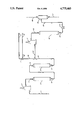
- the Drawing is a simplified process flow diagram of a preferred embodiment of the invention wherein hydrocracking feed from line 1 is passed in series flow through a bed of alumina 3 and a bed of activated carbon 5 maintained at an elevated temperature and is then heated, pressurized, and passed into the hydrocracking reaction zone 12.
- a processing problem may occur when it is attempted to hydrocrack a heavy or residual oil such as a vacuum gas oil.
- This problem often arises when the hydrocracking catalyst comprises a zeolitic component as described in more detail below but may also arise in the absence of this component.
- the process tends to produce a small amount of high molecular weight polycyclic aromatic compounds, commonly referred to as PNA's or benzocoronenes. These materials may plate out or foul various parts of the refining equipment as they have a very low solubility level in the product hydrocarbon.
- PNA deposits tend to accumulate on the cold surfaces of heat exchangers used to recover heat from the effluent of the hydrocracking reaction zone.
- the coating caused by PNA deposits decreases the efficiency of the heat recovery step and may lead to undesirably high pressure drops within the heat exchanger. At an extreme the deposits may require termination of the processing in order to clean the heat exchangers.
- polycyclic aromatic hydrocarbons PNA's
- polynuclear aromatics are used interchangeably herein to refer to the heavy aromatic hydrocarbons having nine or more "benzene rings” and which are produced in the hydrocracking reaction zone. These compounds have been characterized as benzocoronenes in the Hendricks reference cited above.
- PNA precursors Lighter polycyclics having 4-8 rings per molecule are referred to herein as "PNA precursors".
- the subject invention achieves these objectives by performing an upstream treating operation to remove the materials which tend to form the polycyclic aromatic hydrocarbons prior to the passage of the hydrocracking feedstream into the reaction zone.
- the subject invention is illustrated in the Drawing, wherein a feedstream comprising a vacuum gas oil is passed through a fired heating zone 2 via line 1.
- the heated vacuum gas oil stream should have a temperature of from 500°-700° F. (260°-371° C.) and a mildly superatmospheric pressure, such as a pressure of 50 psig (345 kPa g).
- the heated feedstream is then passed through a fixed bed of metal-free alumina catalyst base retained within the first treating zone 3. This contacting step results in the formation of large quantities of polycyclic aromatic hydrocarbons.
- the effluent stream of the first treating zone 3 will therefore be highly similar to the feedstream of line 1 but will have an increased content of the polycyclic aromatic hydrocarbons.
- the effluent stream of the first treating zone is passed through line 4 into a second treating zone 5.
- the second treating zone comprises a fixed bed of small diameter particulate activated carbon and is maintained at substantially the same pressure and temperature as the first treating zone.
- the second treating zone could be operated at different conditions, such as a reduced temperature
- the first and second treating zone are preferably operated at the same conditions of temperature and pressure except for whatever temperature and pressure differences result from the transportation of the process streams between the two zones and unavoidable pressure or temperature changes within the treating zones themselves.
- the effluent of the first treating zone is contacted with the activated charcoal or other adsorbent in a manner which results in the selective separation of the polycyclic aromatic hydrocarbons from the vacuum gas oil boiling range hydrocarbons and the accumulation of these polycyclic compounds on the activated carbon.
- a second treating zone effluent stream removed through line 6 which has essentially the same composition as the feedstream of line 1 but has a much reduced concentration of polycyclic aromatic as compared to the first treating zone effluent stream of line 4.
- Fresh or makeup hydrogen from line 7 is combined with a recycle stream of line 8, preferably containing an admixture of recycled hydrogen-rich gas and any recycled hydrocarbons, with these two streams being transported through line 9 to the junction of line 6.
- the resultant admixture of the vacuum gas oil and hydrogen is passed through line 10 into a second fired heating means 11.
- a second heating means may not be required in all instances. Its function is to heat the resultant admixture to the desired inlet temperature of the downstream hydrocracking reaction zone 12.
- the heated material flowing through line 10 is treated in a conventional manner in the hydrocracking reaction zone 12 by contacting it with one or more beds of a solid hydrocracking catalyst maintained at hydrocracking conditions.
- the effluent stream of the hydrocracking reaction zone will comprise an admixture of converted hydrocarbons, unconverted hydrocarbons, by-product light gases and residual unused hydrogen but will have a lower concentration of polycyclic aromatic hydrocarbons than prior art processes.
- the effluent stream of the hydrocracking reaction zone is passed via line 13 through a first heat exchange means 14.
- the function of this heat exchange means is to recover heat from the effluent stream as by exchange against the feedstream to the process.
- the cooling which occurs in the heat exchange means 14 also promotes the separation in the flash vessel 15 of the effluent into a liquid phase hydrocarbon stream removed in line 17 and a vapor phase stream removed in line 16.
- the material of line 17 will normally be passed into a second separation stage operated at a lower pressure.
- the liquid phase stream remaining after this second separation step is passed into one or more fractionation columns such as a stripping column and a product fractionation column and separated into various boiling point ranges such as gasoline, diesel fuel, and unconverted bottoms material.
- the vapor phase stream of line 16 will customarily be further cooled and passed into one or more vapor-liquid separation stages for the recovery of additional product hydrocarbons and to increase the hydrogen content of the ultimately recovered vapor phase stream.
- a major portion of the vapor phase stream is recycled to the reaction zone to conserve hydrogen while a minor portion may be discharged to balance the production of light hydrocarbons.
- the recycle gas stream may be passed through a treating step as for the removal of sulfur compounds.
- no hydrogen is commingled with the feedstream of line 1. That is, the feedstream to the first treating zone is substantially free of uncombined hydrogen, with this term meaning that no hydrogen is intentionally added to the feed and that only residual dissolved hydrogen which may be present due to upstream treating operations is present in the feedstream.
- the concentration of chemically uncombined or free hydrogen in the material entering the first and second treating zones is less than 30 standard cubic feet per barrel (5.8 meters 3 per meter 3 ). This is because it is believed that a low hydrogen partial pressure promotes PNA formation.
- the material flowing through the first and second treating zones will therefore normally be totally liquid phase material, whereas in the hydrocracking zone there will be vapor phase material due to the high amount of hydrogen circulated through the hydrocracking zone.
- the ability to reduce the formation of polycyclic aromatic hydrocarbons in the reaction zone and to reduce their concentration in process streams of a hydrocracking unit has advantages other than the prevention of fouling of heat exchange surfaces. These same materials also tend to deactivate the catalyst. Therefore, by removing polycyclic aromatic hydrocarbons from the initial feedstream and by reducing the tendency for their formation within the reaction zone, the average concentration of these materials in the fluids contacting the hydrocracking catalyst is reduced. The result is that a lower amount of catalyst is required in the hydrocracking zone to allow stable operation for the same length of time as compared to when these materials are present.
- the same operating advantage can be used in other manners as by providing the ability to operate at a higher severity during a run or cycle of the same length. Alternatively, rather than increasing the severity of operation conditions the process may be adapted to processing feedstreams which place a greater demand upon the catalyst system and would normally tend to result in a shorter catalyst life.
- the first treating zone will preferably contain a particulate solid which for hydrocracking purposes would be considered noncatalytic. That is, the solid material employed within the first treating zone should have essentially no or perhaps at most miniminal activity as a hydrocracking catalyst.
- the particulate material is highly porous in nature and is present in the form of small particles such as spheres or extrudates having sizes roughly equivalent to that employed for hydrocracking catalyst.
- the particulate material comprises a porous metal oxide, with an alumina-based compound being highly preferred. The presence of small amounts of other amorphous materials or of zeolitic materials is acceptable if they do not tend to adversely effect the functionality of the particulate material for selectively promoting the formation of polycyclic hydrocarbons.
- These treating materials of the first zone should be substantially free of any catalytic metal component, a term used herein to refer to the metals normally deposited on a support material of a catalyst to improve the activity or selectivity of the final catalyst composite.
- the treating materials will therefore preferably contain less than 0.2 weight percent of a metal component, with the metals of the metal component normally being chosen from the group consisting of such metals as iron, cobalt, molybdenum, nickel, tungsten, and the platinum group metals.
- the treating material will preferably have a surface area greater than 150 meters 2 per gram and a pore volume greater than 0.4 grams per cc.
- One highly preferred treating particle for use in the first treating zone comprises an alumina hydrocracking catalyst base material having a significant percentage, at least 20%, of pores greater than 300 A in diameter.
- base material it is meant that this is the material on which the metal component of a hydrocracking catalyst is deposited during the preparation of a hydrocracking catalyst.
- This material will preferably contain at least 80 weight percent alumina and preferably 90 weight percent alumina.
- the second treating zone will also contain a finely divided particulate material.
- the function of this material is the accumulation or adsorption of the polycyclic aromatic hydrocarbons produced in the first treating zone. Accordingly, it preferably has essentially no ability to promote the production or formation of these compounds.
- the material employed in the second treating zone is therefore an essentially inert adsorbent.
- the size and configuration of the particulate material of this treating zone is chosen on the basis of pressure drop and flow considerations through the treating zone, surface area, and treating capacity related to the size of the particle and finally those dictates imposed by commercial availability and costs.
- a wide variety of materials are known to function as an adsorbent for the polycyclic aromatic hydrocarbons, with these materials including various silica gels, large pore aluminas, and various charcoals and other carbon-based materials.
- the treating particles are rich in carbon.
- Charcoals therefore comprise a preferred adsorbent.
- the charcoals those which are substantially free of metals such as those derived from coconuts or other low metal content organic material are preferred.
- a highly preferred material for the second treating zone is a large pore activated carbon. This material has proven to be very effective for selectively separating polycyclic aromatic hydrocarbons from a vacuum gas oil boiling range material. Commercially available activated charcoal has been found to work effectively.
- the treating zones are operated at relatively mild conditions of temperature and pressure as compared to the hydrocracking zone. These mild conditions allow the use of less expensive pressure vessels and piping thereby increasing the commercial feasibility of the overall process.
- the treating zones are preferably operated within a pressure range of 50 to about 500 psig (345- 3447 kPa g) and at a temperature of about 250 to about 600 degrees F. (121 to 316 degrees C.) with temperatures above 500 degrees F. (260 degrees C.) being highly preferred.
- the treating zones may be of approximately equal volume.
- the second zone functions to adsorb PNA's its useful onstream life is limited by the adsorptive capacity of the adsorbent. Therefore the second zone is preferably operated at a lower space velocity.
- a broad range of liquid hourly space velocities (L.H.S.V.) for each of the two individual zones is from 0.1 to 2.5 hr -1 .
- a preferred range of space velocities is from 0.4 to 1.5 hr -1 .
- Representative space velocities are 1.0 hr -1 for the first zone and 0.5 hr -1 for the second zone.
- the hydrocracking catalyst may be prepared using starting material having the essential X-ray powder diffraction pattern of zeolite Y set forth in U.S. Pat. No. 3,130,007.
- the starting material may be modified by techniques known in the art which provide a desired form of the zeolite. Thus, modification techniques such as hydrothermal treatment at increased temperatures, calcination, impregnation, or reaction with an acidity strength inhibiting specie, crystallization and any combination of these are contemplated.
- the Y-type zeolite preferred for use in the present invention will possess a unit cell size between about 24.20 Angstroms and 24.45 Angstroms.
- the zeolite unit cell size will be in the range of about 24.20 to 24.40 Angstroms and most preferably about 24.30 Angstroms.
- the hydrocracking catalyst composite should comprise between 2 wt. % and 20 wt. % of a Y-type zeolite, and preferably between 2 wt. % and 10 wt. %.
- the catalyst composition should also comprise a porous refractory inorganic oxide matrix which may form between 2 and 98 wt. %, and preferably between 5 and 95 wt. % of the support of the finished catalyst composite.
- the matrix may comprise any known refractory inorganic oxide such as alumina, magnesia, silica, titania, zirconia, silica-alumina and the like and combinations thereof.
- a preferred matrix comprises silica-alumina or alumina.
- the most preferred matrix comprises a mixture of silica-alumina and alumina wherein said silica-alumina comprises between 5 and 45 wt. % of said matrix. It is also preferred that the support comprises from about 5 wt. % to about 45 wt. % alumina.
- the silica-alumina component may be produced by any of the numerous techniques which are rather well defined in the prior art relating thereto. Such techniques include the acid-treating of a natural clay or sand, co-precipitation or successive precipitation from hydrosols. These techniques are frequently coupled with one or more activating treatments including hot oil aging, steaming, drying, oxidizing, reducing, calcining, etc.
- the pore structure of the support or carrier commonly defined in terms of surface area, pore diameter and pore volume, may be developed to specified limits by any suitable means including aging a hydrosol and/or hydrogel under controlled acidic or basic conditions at ambient or elevated temperature, or by gelling the carrier at a critical pH or by treating the carrier with various inorganic or organic reagents.
- a finished catalyst for utilization in the subject hydrocracking process should have a surface area of about 200 to 700 square meters per gram, a pore diameter of about 20 to about 300 Angstroms, a pore volume of about 0.10 to about 0.80 milliliters per gram, and apparent bulk density within the range of from about 0.50 to about 0.90 gram/cc. Surface areas above 350 m 2 /gm are greatly preferred.
- the alumina component of the hydrocracking catalyst may be any of the various hydrous aluminum oxides or alumina gels such as alpha-alumina monohydrate of the boehmite structure, alpha-alumina trihydrate of the gibbsite structure, beta-alumina trihydrate of the bayerite structure, and the like.
- a particularly preferred alumina is referred to as Ziegler alumina and has been characterized in U.S. Pat. Nos. 3,852,190 and 4,012,313 as a by-product from a Ziegler higher alcohol synthesis reaction as described in Ziegler's U.S. Pat. No. 2,892,858.
- a preferred alumina is presently available from the Conoco Chemical Division of Continental Oil Company under the trademark "Catapal".
- the material is an extremely high purity alpha-alumina monohydrate (boehmite) which, after calcination at a high temperature, has been shown to yield a high purity gamma-alumina.
- the precise physical characteristics of the catalyst such as shape and surface area are not considered to be limiting upon the utilization of the present invention.
- the catalyst may, for example, exist in the form of pills, pellets, granules, broken fragments, spheres, or various special shapes such as trilobal extrudates, disposed as a fixed bed within a reaction zone.
- the catalyst may be prepared in a suitable form for use in moving bed reaction zones in which the hydrocarbon charge stock and catalyst are passed either in countercurrent flow or in co-current flow, or in fluidized-solid processes in which the charge stock is passed upward through a turbulent bed of finely divided catalyst, or in the suspension process, in which the catalyst is slurried in the charge stock and the resulting mixture is conveyed into the reaction zone.
- the charge stock may be passed through the reactor(s) in the liquid or mixed phase, and in either upward or downward flow.
- the catalyst particles may be prepared by any known method in the art including the well-known oil drop and extrusion methods.
- catalyst particles may be prepared by first suspending the selected zeolite powder in a suitable sol. Active metal components may also be incorporated into the sol. The sol admixture may then be passed as droplets into an oil bath which is maintained at an elevated temperature and retained in the oil bath until the sol droplets set to gelled spheres. The spherical particles may then be withdrawn from the oil bath and thereafter aged in a suspending medium at an elevated temperature for a suitable time period. The spherical particles may then be dried and calcined. If an alumina or silica-alumina oxide matrix is desired, the oil drop method may be carried out in accordance with U.S. Pat. No. 2,620,314 or 3,003,972, respectively, the teachings of which are incorporated herein by reference.
- a preferred method of preparing a catalyst for use in the present invention is to simultaneously co-mull the selected zeolite with both alumina and amorphous silica-alumina. After mulling, the admixture is extruded through a die having suitable openings such as circular openings so as to produce an extrudate material of cylindrical shape. The extrudate can be cut in 1/2 to 1/4 inch lengths and then dried and calcined at elevated temperatures and conditions known in the art.
- hydrogenation components may be added before or during the oil drop or extrusion methods, hydrogenation components are preferably composited with the catalyst by impregnation after the selected zeolite and refractory inorganic oxide materials have been formed, dried and calcined. Impregnation of the metal hydrogenation component into the particles may be carried out in any manner known in the art including evaporative, dip and vacuum impregnation techniques. In general, the dried and calcined particles are contacted with one or more solutions which contain the desired hydrogenation components in dissolved form. After a suitable contact time, the composite particles are dried and calcined to produce finished catalyst particles. Further information on the preparation of suitable hydrocracking may be obtained by reference to U.S. Pat. Nos. 4,422,959; 4,576,711; 4,661,239; 4,686,030; and, 4,695,368 which are incorporated herein by reference.
- Hydrogenation components contemplated are those catalytically active components selected from Group VIB and Group VIII metals and their compounds. Generally, the amount of hydrogenation components present in the final catalyst composition is small compared to the quantity of the other above-mentioned components combined therewith.
- the Group VIII component generally comprises about 0.1 to about 30% by weight, preferably about 1 to about 15% by weight of the final catalytic composite calculated on an elemental basis.
- the Group VIB component comprises about 0.05 to about 30% by weight, preferably about 0.5 to about 15% by weight of the final catalytic composite calculated on an elemental basis.
- the hydrogenation components contemplated include one or more metals chosen from the group consisting of molybdenum, tungsten, chromium, iron, cobalt, nickel, platinum, palladium, iridium, osmium, rhodium, rudinium and mixtures thereof.
- the hydrogenation components will most likely be present in the oxide form after calcination in air and may be converted to the sulfide form if desired by contact at elevated temperatures with a reducing atmosphere comprising hydrogen sulfide, a mercaptan or other sulfur containing compound.
- a phosphorus component may also be incorporated into the catalyst. Usually phosphorus is present in the catalyst in the range of 1 to 30 wt. % and preferably 3 to 15 wt. % calculated as P 2 O 5 .
- boron may also be present in the catalytic composite.
- the subject process is especially useful in the production of middle distillate fractions boiling in the range of about 300°-700° F. (149°-371° C.) as determined by the appropriate ASTM test procedure.
- useful hydrogenation reactions such as hydrodenitrification and hydrodesulfurization will occur simultaneously with hydrocracking of heavier feedstocks.
- Typical feedstocks include virtually any heavy mineral or synthetic oils and fractions thereof.
- feedstocks as straight run gas oils, vacuum gas oils, demetallized oils, atmospheric residue, deasphalted vacuum residue, coker distillates, cat cracker distillates, shale oil, tar sand oil, coal liquids, and the like are contemplated.
- the preferred feedstock will have a boiling point range starting at a temperature above 160° Celsius.
- Preferred feedstocks include gas oils having at least 50% volume of their components boiling above 700° F. (371° C.).
- the hydrocracking feedstock may contain nitrogen usually present as organonitrogen compounds in amounts between 1 ppm and 1.0 wt. %.
- the feed will normally contain sulfur containing compounds sufficient to provide a sulfur content greater than 0.15 wt. %. It may also contain mono- and/or polynuclear aromatic compounds in amounts of 80 volume percent and higher.
- Hydrocracking conditions employed in the subject process are those customarily employed in the art for hydrocracking processes.
- Hydrocracking reaction temperatures are in the range of 400° to 1200° F. (204°-649° C.), preferably between 600° and 950° F. (316°-510° C.).
- Reaction pressures are in the range of atmospheric to about 3,500 psig (24,132 kPa g), preferably between 200 and 3000 psig (1379-20,685 kPa g).
- Contact times usually correspond to liquid hourly space velocities (LHSV) in the range of about 0.1 hr -1 to 15 hr -1 , preferably between about 0.2 and 3 hr -1 .
- LHSV liquid hourly space velocities
- Hydrogen circulation rates are in the range of 1,000 to 50,000 standard cubic feet (scf) per barrel of charge (178-8,888 std. m 3 /m 3 ), preferably between 2,000 and 30,000 scf per barrel of charge (355-5,333 std. m 3 /m 3 ).
- reaction zone effluent of a hydrocracking process is normally removed from the catalyst bed, subjected to partial condensation and vapor-liquid separation and then fractionated to recover the various components thereof.
- the hydrogen, and if desired some or all of the unconverted heavier materials, are recycled to the reactor.
- Conventional product recovery schemes are therefore suitable for use with the subject invention.
- a staged (not simultaneous series flow) simulation of a commercial operation is performed using pilot plant scale equipment. This is based on work which was done separately on each individual step.
- a vacuum gas oil feed having the properties listed in Table 1 is processed to yield an overall liquid product as also described in Table 1.
- the same feed is then treated in accordance with the invention by passage over an all alumina hydrocracking catalyst base at a temperature of 550 degrees F. (288 degrees C.) an L.H.S.V. of 1.0 hr -1 and a pressure of 100 psig (689 kPa g).
- the concentration of PNA precursors in the feed stream is approximately 200 wt. ppm and the 11+ ring PNA concentration is not detectable.
- the concentration of PNA precursors in the effluent of the first treating zone is below the minimum level of detection of the analytical method employed, while the level of 11+ ring PNA's has increased to approximately 200 wt. ppm.
- the effluent of the first treating zone is passed through a bed of fresh activated charcoal (Calgon CAL) maintained at the same temperature and pressure as the first treating zone but at an L.H.S.V. of 0.5 hr -1 . This results in the concentration of PNA's being reduced to below detection limits.
- the effluent of the second treating zone is then hydrocracked in the same manner and produces a product essentially equal in properties to the product of the reference run set out in the Table.
- the effluent of the reference run contains about 200 wt. ppm of PNA's while the effluent produced using the subject treating steps contains less than 50 wt. ppm PNA's. Therefore the subject invention is shown to greatly decrease the PNA content of the hydrocracker effluent.
Landscapes
- Chemical & Material Sciences (AREA)
- Oil, Petroleum & Natural Gas (AREA)
- Engineering & Computer Science (AREA)
- Chemical Kinetics & Catalysis (AREA)
- General Chemical & Material Sciences (AREA)
- Organic Chemistry (AREA)
- Production Of Liquid Hydrocarbon Mixture For Refining Petroleum (AREA)
Abstract
Description
              TABLE 1
______________________________________
Hydrocracker Stream Properties
            Feed      Effluent
______________________________________
API           20.1        40
IBP (°F.)
              648 (339° C.)
                          90 (32° C.)
50% pt        793 (426° C.)
                          610 (321° C.)
EP            1000 (538° C.)
                          910 (487° C.)
Sulfur, wt. % 1.71        <0.01
Nitrogen, wt. %
              0.16        <0.01
______________________________________
Claims (12)
Priority Applications (1)
| Application Number | Priority Date | Filing Date | Title |
|---|---|---|---|
| US07/137,697 US4775460A (en) | 1987-12-24 | 1987-12-24 | Hydrocracking process with feed pretreatment |
Applications Claiming Priority (1)
| Application Number | Priority Date | Filing Date | Title |
|---|---|---|---|
| US07/137,697 US4775460A (en) | 1987-12-24 | 1987-12-24 | Hydrocracking process with feed pretreatment |
Publications (1)
| Publication Number | Publication Date |
|---|---|
| US4775460A true US4775460A (en) | 1988-10-04 |
Family
ID=22478662
Family Applications (1)
| Application Number | Title | Priority Date | Filing Date |
|---|---|---|---|
| US07/137,697 Expired - Lifetime US4775460A (en) | 1987-12-24 | 1987-12-24 | Hydrocracking process with feed pretreatment |
Country Status (1)
| Country | Link |
|---|---|
| US (1) | US4775460A (en) |
Cited By (64)
| Publication number | Priority date | Publication date | Assignee | Title |
|---|---|---|---|---|
| US4929334A (en) * | 1988-11-18 | 1990-05-29 | Mobil Oil Corp. | Fluid-bed reaction process |
| US4950386A (en) * | 1988-08-15 | 1990-08-21 | Exxon Research And Engineering Company | Acidic promotion of transition metal sulfide catalysts for selective hydrogenation |
| US4954242A (en) * | 1989-07-19 | 1990-09-04 | Uop | Process for refractory compound removal in a hydrocracker recycle liquid |
| US5120426A (en) * | 1990-12-21 | 1992-06-09 | Atlantic Richfield Company | Hydrocracking process |
| US5124023A (en) * | 1988-11-28 | 1992-06-23 | Union Oil Company Of California | Continuous removal of polynuclear aromatics from hydrocarbon recycle oil |
| US5300218A (en) * | 1992-06-23 | 1994-04-05 | Shell Oil Company | Reduction of diesel engine particulate emissions by contacting diesel fuel with a carbon molecular sieve adsorbent |
| US5334308A (en) * | 1992-06-23 | 1994-08-02 | Shell Oil Company | Reduction of jet engine smoke emissions by contacting jet fuel with a carbon molecular sieve adsorbent |
| WO1999015605A1 (en) * | 1997-09-25 | 1999-04-01 | Ludger Steinmann | Device and method for upgrading energy- and chemical raw materials by reacting them with cheap raw materials |
| US6258900B1 (en) | 1998-07-16 | 2001-07-10 | Crystaphase International, Inc | Filtration and flow distribution method for chemical reactors |
| US6291603B1 (en) | 1997-07-18 | 2001-09-18 | Crystaphase International, Inc. | Filtration and flow distribution method for chemical reactors using reticulated ceramics with uniform pore distributions |
| US6461497B1 (en) | 1998-09-01 | 2002-10-08 | Atlantic Richfield Company | Reformulated reduced pollution diesel fuel |
| US20040192862A1 (en) * | 2003-03-25 | 2004-09-30 | Glover John N. | Filtration, flow distribution and catalytic method for process streams |
| US20040225085A1 (en) * | 2003-03-25 | 2004-11-11 | Glover John N. | Decontamination of process streams |
| EP1700900A1 (en) | 2005-03-09 | 2006-09-13 | Institut Français du Pétrole | Hydrocracking process with recycling which includes adsorption of polyaromatic compounds from recycled stream using a silica-alumina based adsorbant with limited macropores concentration |
| EP1700899A1 (en) | 2005-03-09 | 2006-09-13 | Institut Français du Pétrole | Hydrocracking process with recycling which includes adsorption of polyaromatic compounds from recycled stream using a silica-alumina based adsorbant with limited macropores concentration |
| US20080105595A1 (en) * | 2006-10-20 | 2008-05-08 | Saudi Arabian Oil Company | Process for removal of nitrogen and poly-nuclear aromatics from hydrocracker and FCC feedstocks |
| US20090156876A1 (en) * | 2007-12-18 | 2009-06-18 | Ou John D Y | Apparatus and Process for Cracking Hydrocarbonaceous Feed Treated to Adsorb Paraffin-Insoluble Compounds |
| US20090321309A1 (en) * | 2006-10-20 | 2009-12-31 | Omer Refa Koseoglu | Process for upgrading hydrocarbon feedstocks using solid adsorbent and membrane separation of treated product stream |
| US8062521B2 (en) | 1998-05-29 | 2011-11-22 | Crystaphase Products, Inc. | Filtering medium and method for contacting solids-containing feeds for chemical reactors |
| US8828219B2 (en) | 2011-01-24 | 2014-09-09 | Saudi Arabian Oil Company | Hydrocracking process with feed/bottoms treatment |
| US20140323788A1 (en) * | 2013-04-24 | 2014-10-30 | Uop, Llc | Process for modifying an apparatus and for removing one or more contaminants |
| US8945372B2 (en) | 2011-09-15 | 2015-02-03 | E I Du Pont De Nemours And Company | Two phase hydroprocessing process as pretreatment for tree-phase hydroprocessing process |
| US9321971B2 (en) | 2009-06-17 | 2016-04-26 | Exxonmobil Chemical Patents Inc. | Removal of asphaltene contaminants from hydrocarbon streams using carbon based adsorbents |
| US10054140B2 (en) | 2016-02-12 | 2018-08-21 | Crystaphase Products, Inc. | Use of treating elements to facilitate flow in vessels |
| US10500581B1 (en) | 2003-03-25 | 2019-12-10 | Crystaphase International, Inc. | Separation method and assembly for process streams in component separation units |
| US10663238B2 (en) | 2017-03-28 | 2020-05-26 | Uop Llc | Detecting and correcting maldistribution in heat exchangers in a petrochemical plant or refinery |
| US10670027B2 (en) | 2017-03-28 | 2020-06-02 | Uop Llc | Determining quality of gas for rotating equipment in a petrochemical plant or refinery |
| US10670353B2 (en) | 2017-03-28 | 2020-06-02 | Uop Llc | Detecting and correcting cross-leakage in heat exchangers in a petrochemical plant or refinery |
| US10678272B2 (en) | 2017-03-27 | 2020-06-09 | Uop Llc | Early prediction and detection of slide valve sticking in petrochemical plants or refineries |
| US10695711B2 (en) | 2017-04-28 | 2020-06-30 | Uop Llc | Remote monitoring of adsorber process units |
| FR3091538A1 (en) | 2019-01-09 | 2020-07-10 | IFP Energies Nouvelles | TWO-STEP HYDROCRACKING PROCESS COMPRISING A HYDROGENATION STAGE UPSTREAM OF THE SECOND HYDROCRACKING STAGE FOR THE PRODUCTION OF MEDIUM DISTILLATES |
| FR3091534A1 (en) | 2019-01-09 | 2020-07-10 | IFP Energies Nouvelles | TWO-STEP HYDROCRACKING PROCESS FOR THE PRODUCTION OF NAPHTA INCLUDING A HYDROGENATION STAGE IMPLEMENTED DOWNSTREAM OF THE SECOND HYDROCRACKING STAGE |
| FR3091533A1 (en) | 2019-01-09 | 2020-07-10 | IFP Energies Nouvelles | TWO-STEP HYDROCRACKING PROCESS FOR THE PRODUCTION OF NAPHTA INCLUDING A HYDROGENATION STAGE IMPLEMENTED BEFORE THE SECOND HYDROCRACKING STAGE |
| FR3091535A1 (en) | 2019-01-09 | 2020-07-10 | IFP Energies Nouvelles | TWO-STAGE HYDROCRACKING PROCESS COMPRISING A HYDROGENATION STAGE DOWNSTREAM OF THE SECOND HYDROCRACKING STAGE FOR THE PRODUCTION OF MEDIUM DISTILLATES |
| FR3091537A1 (en) | 2019-01-09 | 2020-07-10 | IFP Energies Nouvelles | ONE-STEP HYDROCRACKING PROCESS COMPRISING A HYDROGENATION STEP UPSTREAM OR DOWNSTREAM OF THE HYDROCRACKING STEP FOR THE PRODUCTION OF MEDIUM DISTILLATES |
| FR3091536A1 (en) | 2019-01-09 | 2020-07-10 | IFP Energies Nouvelles | ONE-STEP HYDROCRACKING PROCESS COMPRISING A HYDROGENATION STEP UPSTREAM OR DOWNSTREAM OF THE HYDROCRACKING STEP FOR THE PRODUCTION OF NAPHTA |
| US10734098B2 (en) | 2018-03-30 | 2020-08-04 | Uop Llc | Catalytic dehydrogenation catalyst health index |
| US10739798B2 (en) | 2017-06-20 | 2020-08-11 | Uop Llc | Incipient temperature excursion mitigation and control |
| US10744426B2 (en) | 2015-12-31 | 2020-08-18 | Crystaphase Products, Inc. | Structured elements and methods of use |
| US10752845B2 (en) | 2017-03-28 | 2020-08-25 | Uop Llc | Using molecular weight and invariant mapping to determine performance of rotating equipment in a petrochemical plant or refinery |
| US10754359B2 (en) | 2017-03-27 | 2020-08-25 | Uop Llc | Operating slide valves in petrochemical plants or refineries |
| US10752844B2 (en) | 2017-03-28 | 2020-08-25 | Uop Llc | Rotating equipment in a petrochemical plant or refinery |
| US10794644B2 (en) | 2017-03-28 | 2020-10-06 | Uop Llc | Detecting and correcting thermal stresses in heat exchangers in a petrochemical plant or refinery |
| US10839115B2 (en) | 2015-03-30 | 2020-11-17 | Uop Llc | Cleansing system for a feed composition based on environmental factors |
| US10844290B2 (en) | 2017-03-28 | 2020-11-24 | Uop Llc | Rotating equipment in a petrochemical plant or refinery |
| US10901403B2 (en) | 2018-02-20 | 2021-01-26 | Uop Llc | Developing linear process models using reactor kinetic equations |
| US10913905B2 (en) | 2017-06-19 | 2021-02-09 | Uop Llc | Catalyst cycle length prediction using eigen analysis |
| US10953377B2 (en) | 2018-12-10 | 2021-03-23 | Uop Llc | Delta temperature control of catalytic dehydrogenation process reactors |
| US10962302B2 (en) | 2017-03-28 | 2021-03-30 | Uop Llc | Heat exchangers in a petrochemical plant or refinery |
| US10994240B2 (en) | 2017-09-18 | 2021-05-04 | Uop Llc | Remote monitoring of pressure swing adsorption units |
| US11022963B2 (en) | 2016-09-16 | 2021-06-01 | Uop Llc | Interactive petrochemical plant diagnostic system and method for chemical process model analysis |
| US11037376B2 (en) | 2017-03-28 | 2021-06-15 | Uop Llc | Sensor location for rotating equipment in a petrochemical plant or refinery |
| WO2021118612A1 (en) | 2019-12-11 | 2021-06-17 | Saudi Arabian Oil Company | Needle coke production from hpna recovered from hydrocracking unit |
| US11052363B1 (en) | 2019-12-20 | 2021-07-06 | Crystaphase Products, Inc. | Resaturation of gas into a liquid feedstream |
| US11105787B2 (en) | 2017-10-20 | 2021-08-31 | Honeywell International Inc. | System and method to optimize crude oil distillation or other processing by inline analysis of crude oil properties |
| US11130111B2 (en) | 2017-03-28 | 2021-09-28 | Uop Llc | Air-cooled heat exchangers |
| US11130692B2 (en) | 2017-06-28 | 2021-09-28 | Uop Llc | Process and apparatus for dosing nutrients to a bioreactor |
| US11194317B2 (en) | 2017-10-02 | 2021-12-07 | Uop Llc | Remote monitoring of chloride treaters using a process simulator based chloride distribution estimate |
| US11365886B2 (en) | 2017-06-19 | 2022-06-21 | Uop Llc | Remote monitoring of fired heaters |
| US11384299B2 (en) | 2019-12-19 | 2022-07-12 | Saudi Arabian Oil Company | Systems and processes for upgrading and converting crude oil to petrochemicals through steam cracking |
| US11396002B2 (en) | 2017-03-28 | 2022-07-26 | Uop Llc | Detecting and correcting problems in liquid lifting in heat exchangers |
| CN115287089A (en) * | 2022-09-02 | 2022-11-04 | 香港理工大学 | Method for preparing aromatic monomer from lignin |
| US11676061B2 (en) | 2017-10-05 | 2023-06-13 | Honeywell International Inc. | Harnessing machine learning and data analytics for a real time predictive model for a FCC pre-treatment unit |
| US11752477B2 (en) | 2020-09-09 | 2023-09-12 | Crystaphase Products, Inc. | Process vessel entry zones |
Citations (15)
| Publication number | Priority date | Publication date | Assignee | Title |
|---|---|---|---|---|
| US2796387A (en) * | 1954-07-29 | 1957-06-18 | Standard Oil Co | Catalytic cracking of pretreated hydrocarbon oils |
| US3238123A (en) * | 1962-05-11 | 1966-03-01 | Exxon Research Engineering Co | Catalytic hydrofining process |
| US3619407A (en) * | 1969-12-17 | 1971-11-09 | Union Oil Co | Hydrocracking process with benzcoronenes bleedstream |
| US3623973A (en) * | 1969-11-25 | 1971-11-30 | Bethlehem Steel Corp | Process for producing one- and two-ring aromatics from polynuclear aromatic feedstocks |
| US3691063A (en) * | 1971-03-18 | 1972-09-12 | Sun Oil Co | Residual fuel oil hydrocracking process |
| US3767563A (en) * | 1971-12-23 | 1973-10-23 | Texaco Inc | Adsorption-desorption process for removing an unwanted component from a reaction charge mixture |
| US4203825A (en) * | 1979-02-02 | 1980-05-20 | Exxon Research & Engineering Co. | Method for removing coronene from heat exchangers |
| US4366047A (en) * | 1981-06-02 | 1982-12-28 | Exxon Research And Engineering Co. | Combination hydrorefining, heat-treating and hydrocracking process |
| US4411768A (en) * | 1979-12-21 | 1983-10-25 | The Lummus Company | Hydrogenation of high boiling hydrocarbons |
| US4447315A (en) * | 1983-04-22 | 1984-05-08 | Uop Inc. | Hydrocracking process |
| US4608153A (en) * | 1984-07-30 | 1986-08-26 | Exxon Research And Engineering Co. | Process for the removal of polynuclear aromatic hydrocarbon compounds from admixtures of liquid hydrocarbon compounds |
| US4618412A (en) * | 1985-07-31 | 1986-10-21 | Exxon Research And Engineering Co. | Hydrocracking process |
| US4624776A (en) * | 1984-03-09 | 1986-11-25 | Exxon Research And Engineering Company | Selective removal of coke precursors from hydrocarbon feedstock |
| US4634516A (en) * | 1985-11-22 | 1987-01-06 | Shell Oil Company | Slurry treatment of a gas oil or kerosene feed stock for a steam cracking procedure |
| US4661239A (en) * | 1985-07-02 | 1987-04-28 | Uop Inc. | Middle distillate producing hydrocracking process |
-
1987
- 1987-12-24 US US07/137,697 patent/US4775460A/en not_active Expired - Lifetime
Patent Citations (15)
| Publication number | Priority date | Publication date | Assignee | Title |
|---|---|---|---|---|
| US2796387A (en) * | 1954-07-29 | 1957-06-18 | Standard Oil Co | Catalytic cracking of pretreated hydrocarbon oils |
| US3238123A (en) * | 1962-05-11 | 1966-03-01 | Exxon Research Engineering Co | Catalytic hydrofining process |
| US3623973A (en) * | 1969-11-25 | 1971-11-30 | Bethlehem Steel Corp | Process for producing one- and two-ring aromatics from polynuclear aromatic feedstocks |
| US3619407A (en) * | 1969-12-17 | 1971-11-09 | Union Oil Co | Hydrocracking process with benzcoronenes bleedstream |
| US3691063A (en) * | 1971-03-18 | 1972-09-12 | Sun Oil Co | Residual fuel oil hydrocracking process |
| US3767563A (en) * | 1971-12-23 | 1973-10-23 | Texaco Inc | Adsorption-desorption process for removing an unwanted component from a reaction charge mixture |
| US4203825A (en) * | 1979-02-02 | 1980-05-20 | Exxon Research & Engineering Co. | Method for removing coronene from heat exchangers |
| US4411768A (en) * | 1979-12-21 | 1983-10-25 | The Lummus Company | Hydrogenation of high boiling hydrocarbons |
| US4366047A (en) * | 1981-06-02 | 1982-12-28 | Exxon Research And Engineering Co. | Combination hydrorefining, heat-treating and hydrocracking process |
| US4447315A (en) * | 1983-04-22 | 1984-05-08 | Uop Inc. | Hydrocracking process |
| US4624776A (en) * | 1984-03-09 | 1986-11-25 | Exxon Research And Engineering Company | Selective removal of coke precursors from hydrocarbon feedstock |
| US4608153A (en) * | 1984-07-30 | 1986-08-26 | Exxon Research And Engineering Co. | Process for the removal of polynuclear aromatic hydrocarbon compounds from admixtures of liquid hydrocarbon compounds |
| US4661239A (en) * | 1985-07-02 | 1987-04-28 | Uop Inc. | Middle distillate producing hydrocracking process |
| US4618412A (en) * | 1985-07-31 | 1986-10-21 | Exxon Research And Engineering Co. | Hydrocracking process |
| US4634516A (en) * | 1985-11-22 | 1987-01-06 | Shell Oil Company | Slurry treatment of a gas oil or kerosene feed stock for a steam cracking procedure |
Cited By (88)
| Publication number | Priority date | Publication date | Assignee | Title |
|---|---|---|---|---|
| US4950386A (en) * | 1988-08-15 | 1990-08-21 | Exxon Research And Engineering Company | Acidic promotion of transition metal sulfide catalysts for selective hydrogenation |
| US4929334A (en) * | 1988-11-18 | 1990-05-29 | Mobil Oil Corp. | Fluid-bed reaction process |
| US5124023A (en) * | 1988-11-28 | 1992-06-23 | Union Oil Company Of California | Continuous removal of polynuclear aromatics from hydrocarbon recycle oil |
| US4954242A (en) * | 1989-07-19 | 1990-09-04 | Uop | Process for refractory compound removal in a hydrocracker recycle liquid |
| US5120426A (en) * | 1990-12-21 | 1992-06-09 | Atlantic Richfield Company | Hydrocracking process |
| US5300218A (en) * | 1992-06-23 | 1994-04-05 | Shell Oil Company | Reduction of diesel engine particulate emissions by contacting diesel fuel with a carbon molecular sieve adsorbent |
| US5334308A (en) * | 1992-06-23 | 1994-08-02 | Shell Oil Company | Reduction of jet engine smoke emissions by contacting jet fuel with a carbon molecular sieve adsorbent |
| US6291603B1 (en) | 1997-07-18 | 2001-09-18 | Crystaphase International, Inc. | Filtration and flow distribution method for chemical reactors using reticulated ceramics with uniform pore distributions |
| WO1999015605A1 (en) * | 1997-09-25 | 1999-04-01 | Ludger Steinmann | Device and method for upgrading energy- and chemical raw materials by reacting them with cheap raw materials |
| US8062521B2 (en) | 1998-05-29 | 2011-11-22 | Crystaphase Products, Inc. | Filtering medium and method for contacting solids-containing feeds for chemical reactors |
| US6258900B1 (en) | 1998-07-16 | 2001-07-10 | Crystaphase International, Inc | Filtration and flow distribution method for chemical reactors |
| US6461497B1 (en) | 1998-09-01 | 2002-10-08 | Atlantic Richfield Company | Reformulated reduced pollution diesel fuel |
| US20040225085A1 (en) * | 2003-03-25 | 2004-11-11 | Glover John N. | Decontamination of process streams |
| US7265189B2 (en) | 2003-03-25 | 2007-09-04 | Crystaphase Products, Inc. | Filtration, flow distribution and catalytic method for process streams |
| US20040192862A1 (en) * | 2003-03-25 | 2004-09-30 | Glover John N. | Filtration, flow distribution and catalytic method for process streams |
| US7393510B2 (en) | 2003-03-25 | 2008-07-01 | Crystaphase International, Inc. | Decontamination of process streams |
| US10543483B2 (en) | 2003-03-25 | 2020-01-28 | Crystaphase International, Inc. | Separation method and assembly for process streams in component separation units |
| US10525456B2 (en) | 2003-03-25 | 2020-01-07 | Crystaphase International, Inc. | Separation method and assembly for process streams in component separation units |
| US10500581B1 (en) | 2003-03-25 | 2019-12-10 | Crystaphase International, Inc. | Separation method and assembly for process streams in component separation units |
| EP1700900A1 (en) | 2005-03-09 | 2006-09-13 | Institut Français du Pétrole | Hydrocracking process with recycling which includes adsorption of polyaromatic compounds from recycled stream using a silica-alumina based adsorbant with limited macropores concentration |
| EP1700899A1 (en) | 2005-03-09 | 2006-09-13 | Institut Français du Pétrole | Hydrocracking process with recycling which includes adsorption of polyaromatic compounds from recycled stream using a silica-alumina based adsorbant with limited macropores concentration |
| US8246814B2 (en) | 2006-10-20 | 2012-08-21 | Saudi Arabian Oil Company | Process for upgrading hydrocarbon feedstocks using solid adsorbent and membrane separation of treated product stream |
| US20080105595A1 (en) * | 2006-10-20 | 2008-05-08 | Saudi Arabian Oil Company | Process for removal of nitrogen and poly-nuclear aromatics from hydrocracker and FCC feedstocks |
| US20090321309A1 (en) * | 2006-10-20 | 2009-12-31 | Omer Refa Koseoglu | Process for upgrading hydrocarbon feedstocks using solid adsorbent and membrane separation of treated product stream |
| US7763163B2 (en) * | 2006-10-20 | 2010-07-27 | Saudi Arabian Oil Company | Process for removal of nitrogen and poly-nuclear aromatics from hydrocracker feedstocks |
| US7867381B2 (en) | 2006-11-06 | 2011-01-11 | Saudi Arabian Oil Company | Process for removal of nitrogen and poly-nuclear aromatics from FCC feedstocks |
| US20100252483A1 (en) * | 2006-11-06 | 2010-10-07 | Omer Refa Koseoglu | Process for removal of nitrogen and poly-nuclear aromatics from fcc feedstocks |
| US20090156876A1 (en) * | 2007-12-18 | 2009-06-18 | Ou John D Y | Apparatus and Process for Cracking Hydrocarbonaceous Feed Treated to Adsorb Paraffin-Insoluble Compounds |
| US9321971B2 (en) | 2009-06-17 | 2016-04-26 | Exxonmobil Chemical Patents Inc. | Removal of asphaltene contaminants from hydrocarbon streams using carbon based adsorbents |
| US9534179B2 (en) | 2011-01-24 | 2017-01-03 | Saudi Arabian Oil Company | Hydrocracking process with feed/bottoms treatment |
| US8828219B2 (en) | 2011-01-24 | 2014-09-09 | Saudi Arabian Oil Company | Hydrocracking process with feed/bottoms treatment |
| US8945372B2 (en) | 2011-09-15 | 2015-02-03 | E I Du Pont De Nemours And Company | Two phase hydroprocessing process as pretreatment for tree-phase hydroprocessing process |
| US20140323788A1 (en) * | 2013-04-24 | 2014-10-30 | Uop, Llc | Process for modifying an apparatus and for removing one or more contaminants |
| US10839115B2 (en) | 2015-03-30 | 2020-11-17 | Uop Llc | Cleansing system for a feed composition based on environmental factors |
| US10744426B2 (en) | 2015-12-31 | 2020-08-18 | Crystaphase Products, Inc. | Structured elements and methods of use |
| US11000785B2 (en) | 2015-12-31 | 2021-05-11 | Crystaphase Products, Inc. | Structured elements and methods of use |
| US11156240B2 (en) | 2016-02-12 | 2021-10-26 | Crystaphase Products, Inc. | Use of treating elements to facilitate flow in vessels |
| US10662986B2 (en) | 2016-02-12 | 2020-05-26 | Crystaphase Products, Inc. | Use of treating elements to facilitate flow in vessels |
| US11754100B2 (en) | 2016-02-12 | 2023-09-12 | Crystaphase Products, Inc. | Use of treating elements to facilitate flow in vessels |
| US10655654B2 (en) | 2016-02-12 | 2020-05-19 | Crystaphase Products, Inc. | Use of treating elements to facilitate flow in vessels |
| US10557486B2 (en) | 2016-02-12 | 2020-02-11 | Crystaphase Products, Inc. | Use of treating elements to facilitate flow in vessels |
| US10738806B2 (en) | 2016-02-12 | 2020-08-11 | Crystaphase Products, Inc. | Use of treating elements to facilitate flow in vessels |
| US10920807B2 (en) | 2016-02-12 | 2021-02-16 | Crystaphase Products, Inc. | Use of treating elements to facilitate flow in vessels |
| US10876553B2 (en) | 2016-02-12 | 2020-12-29 | Crystaphase Products, Inc. | Use of treating elements to facilitate flow in vessels |
| US10161428B2 (en) | 2016-02-12 | 2018-12-25 | Crystaphase Products, Inc. | Use of treating elements to facilitate flow in vessels |
| US10054140B2 (en) | 2016-02-12 | 2018-08-21 | Crystaphase Products, Inc. | Use of treating elements to facilitate flow in vessels |
| US11022963B2 (en) | 2016-09-16 | 2021-06-01 | Uop Llc | Interactive petrochemical plant diagnostic system and method for chemical process model analysis |
| US10678272B2 (en) | 2017-03-27 | 2020-06-09 | Uop Llc | Early prediction and detection of slide valve sticking in petrochemical plants or refineries |
| US10754359B2 (en) | 2017-03-27 | 2020-08-25 | Uop Llc | Operating slide valves in petrochemical plants or refineries |
| US10962302B2 (en) | 2017-03-28 | 2021-03-30 | Uop Llc | Heat exchangers in a petrochemical plant or refinery |
| US10670027B2 (en) | 2017-03-28 | 2020-06-02 | Uop Llc | Determining quality of gas for rotating equipment in a petrochemical plant or refinery |
| US10663238B2 (en) | 2017-03-28 | 2020-05-26 | Uop Llc | Detecting and correcting maldistribution in heat exchangers in a petrochemical plant or refinery |
| US11396002B2 (en) | 2017-03-28 | 2022-07-26 | Uop Llc | Detecting and correcting problems in liquid lifting in heat exchangers |
| US11130111B2 (en) | 2017-03-28 | 2021-09-28 | Uop Llc | Air-cooled heat exchangers |
| US11037376B2 (en) | 2017-03-28 | 2021-06-15 | Uop Llc | Sensor location for rotating equipment in a petrochemical plant or refinery |
| US10670353B2 (en) | 2017-03-28 | 2020-06-02 | Uop Llc | Detecting and correcting cross-leakage in heat exchangers in a petrochemical plant or refinery |
| US10752845B2 (en) | 2017-03-28 | 2020-08-25 | Uop Llc | Using molecular weight and invariant mapping to determine performance of rotating equipment in a petrochemical plant or refinery |
| US10844290B2 (en) | 2017-03-28 | 2020-11-24 | Uop Llc | Rotating equipment in a petrochemical plant or refinery |
| US10752844B2 (en) | 2017-03-28 | 2020-08-25 | Uop Llc | Rotating equipment in a petrochemical plant or refinery |
| US10794644B2 (en) | 2017-03-28 | 2020-10-06 | Uop Llc | Detecting and correcting thermal stresses in heat exchangers in a petrochemical plant or refinery |
| US10695711B2 (en) | 2017-04-28 | 2020-06-30 | Uop Llc | Remote monitoring of adsorber process units |
| US11365886B2 (en) | 2017-06-19 | 2022-06-21 | Uop Llc | Remote monitoring of fired heaters |
| US10913905B2 (en) | 2017-06-19 | 2021-02-09 | Uop Llc | Catalyst cycle length prediction using eigen analysis |
| US10739798B2 (en) | 2017-06-20 | 2020-08-11 | Uop Llc | Incipient temperature excursion mitigation and control |
| US11130692B2 (en) | 2017-06-28 | 2021-09-28 | Uop Llc | Process and apparatus for dosing nutrients to a bioreactor |
| US10994240B2 (en) | 2017-09-18 | 2021-05-04 | Uop Llc | Remote monitoring of pressure swing adsorption units |
| US11194317B2 (en) | 2017-10-02 | 2021-12-07 | Uop Llc | Remote monitoring of chloride treaters using a process simulator based chloride distribution estimate |
| US11676061B2 (en) | 2017-10-05 | 2023-06-13 | Honeywell International Inc. | Harnessing machine learning and data analytics for a real time predictive model for a FCC pre-treatment unit |
| US11105787B2 (en) | 2017-10-20 | 2021-08-31 | Honeywell International Inc. | System and method to optimize crude oil distillation or other processing by inline analysis of crude oil properties |
| US10901403B2 (en) | 2018-02-20 | 2021-01-26 | Uop Llc | Developing linear process models using reactor kinetic equations |
| US10734098B2 (en) | 2018-03-30 | 2020-08-04 | Uop Llc | Catalytic dehydrogenation catalyst health index |
| US10953377B2 (en) | 2018-12-10 | 2021-03-23 | Uop Llc | Delta temperature control of catalytic dehydrogenation process reactors |
| FR3091533A1 (en) | 2019-01-09 | 2020-07-10 | IFP Energies Nouvelles | TWO-STEP HYDROCRACKING PROCESS FOR THE PRODUCTION OF NAPHTA INCLUDING A HYDROGENATION STAGE IMPLEMENTED BEFORE THE SECOND HYDROCRACKING STAGE |
| FR3091537A1 (en) | 2019-01-09 | 2020-07-10 | IFP Energies Nouvelles | ONE-STEP HYDROCRACKING PROCESS COMPRISING A HYDROGENATION STEP UPSTREAM OR DOWNSTREAM OF THE HYDROCRACKING STEP FOR THE PRODUCTION OF MEDIUM DISTILLATES |
| FR3091536A1 (en) | 2019-01-09 | 2020-07-10 | IFP Energies Nouvelles | ONE-STEP HYDROCRACKING PROCESS COMPRISING A HYDROGENATION STEP UPSTREAM OR DOWNSTREAM OF THE HYDROCRACKING STEP FOR THE PRODUCTION OF NAPHTA |
| FR3091538A1 (en) | 2019-01-09 | 2020-07-10 | IFP Energies Nouvelles | TWO-STEP HYDROCRACKING PROCESS COMPRISING A HYDROGENATION STAGE UPSTREAM OF THE SECOND HYDROCRACKING STAGE FOR THE PRODUCTION OF MEDIUM DISTILLATES |
| WO2020144097A1 (en) | 2019-01-09 | 2020-07-16 | IFP Energies Nouvelles | Two-stage hydrocracking process comprising a hydrogenation stage downstream of the second hydrocracking stage, for the production of middle distillates |
| WO2020144095A1 (en) | 2019-01-09 | 2020-07-16 | IFP Energies Nouvelles | Two-stage hydrocracking process for producing naphtha, comprising a hydrogenation stage implemented downstream of the second hydrocracking stage |
| WO2020144096A1 (en) | 2019-01-09 | 2020-07-16 | IFP Energies Nouvelles | Two-stage hydrocracking process comprising a hydrogenation stage upstream of the second hydrocracking stage, for the production of middle distillates |
| FR3091534A1 (en) | 2019-01-09 | 2020-07-10 | IFP Energies Nouvelles | TWO-STEP HYDROCRACKING PROCESS FOR THE PRODUCTION OF NAPHTA INCLUDING A HYDROGENATION STAGE IMPLEMENTED DOWNSTREAM OF THE SECOND HYDROCRACKING STAGE |
| FR3091535A1 (en) | 2019-01-09 | 2020-07-10 | IFP Energies Nouvelles | TWO-STAGE HYDROCRACKING PROCESS COMPRISING A HYDROGENATION STAGE DOWNSTREAM OF THE SECOND HYDROCRACKING STAGE FOR THE PRODUCTION OF MEDIUM DISTILLATES |
| WO2021118612A1 (en) | 2019-12-11 | 2021-06-17 | Saudi Arabian Oil Company | Needle coke production from hpna recovered from hydrocracking unit |
| US11384299B2 (en) | 2019-12-19 | 2022-07-12 | Saudi Arabian Oil Company | Systems and processes for upgrading and converting crude oil to petrochemicals through steam cracking |
| US11731095B2 (en) | 2019-12-20 | 2023-08-22 | Crystaphase Products, Inc. | Resaturation of gas into a liquid feedstream |
| US11052363B1 (en) | 2019-12-20 | 2021-07-06 | Crystaphase Products, Inc. | Resaturation of gas into a liquid feedstream |
| US11752477B2 (en) | 2020-09-09 | 2023-09-12 | Crystaphase Products, Inc. | Process vessel entry zones |
| CN115287089A (en) * | 2022-09-02 | 2022-11-04 | 香港理工大学 | Method for preparing aromatic monomer from lignin |
| CN115287089B (en) * | 2022-09-02 | 2023-08-25 | 香港理工大学 | Method for preparing aromatic monomer from lignin |
Similar Documents
| Publication | Publication Date | Title |
|---|---|---|
| US4775460A (en) | Hydrocracking process with feed pretreatment | |
| US5120427A (en) | High conversion high vaporization hydrocracking process | |
| US5904835A (en) | Dual feed reactor hydrocracking process | |
| US5885440A (en) | Hydrocracking process with integrated effluent hydrotreating zone | |
| US5925235A (en) | Middle distillate selective hydrocracking process | |
| US6312586B1 (en) | Multireactor parallel flow hydrocracking process | |
| US6294080B1 (en) | Hydrocracking process product recovery method | |
| US5110444A (en) | Multi-stage hydrodesulfurization and hydrogenation process for distillate hydrocarbons | |
| US5026472A (en) | Hydrocracking process with integrated distillate product hydrogenation reactor | |
| US5164070A (en) | Hydrocracking product recovery process | |
| US6113775A (en) | Split end hydrocracking process | |
| US5114562A (en) | Two-stage hydrodesulfurization and hydrogenation process for distillate hydrocarbons | |
| US4961839A (en) | High conversion hydrocracking process | |
| JP4875907B2 (en) | Hydrocracking process with recycle involving adsorption of polyaromatic compounds from the recirculated portion on a silica-alumina based adsorbent with controlled macropore content | |
| US5393409A (en) | Hydrocracking process using a controlled porosity catalyst | |
| JP4875908B2 (en) | Hydrocracking with recycle involving adsorption of polyaromatic compounds from recycled fractions using adsorbents based on silica-alumina with limited macropore content | |
| JPH0235690B2 (en) | ||
| US4645587A (en) | Process for removing silicon compounds from hydrocarbon streams | |
| US5888377A (en) | Hydrocracking process startup method | |
| WO2006016967A1 (en) | Hydrogenation of aromatics and olefins using a mesoporous catalyst | |
| US3472759A (en) | Process for removal of sulfur and metals from petroleum materials | |
| JP2001500561A (en) | Hydroconversion method | |
| EP0070125B1 (en) | Crystalline silica zeolite-containing catalyst and hydrocarbon hydroprocess utilizing the catalyst | |
| JP2004501223A (en) | Two-stage fluid catalytic cracking method including inter-stage hydrogen treatment | |
| US4940532A (en) | Cleanup of hydrocarbon conversion system |
Legal Events
| Date | Code | Title | Description |
|---|---|---|---|
| AS | Assignment |
Owner name: UOP INC., DES PLAINES, ILLINOIS A CORP. OF DE Free format text: ASSIGNMENT OF ASSIGNORS INTEREST.;ASSIGNOR:RENO, MARK E.;REEL/FRAME:004860/0770 Effective date: 19871216 Owner name: UOP INC., A CORP. OF DE, ILLINOIS Free format text: ASSIGNMENT OF ASSIGNORS INTEREST;ASSIGNOR:RENO, MARK E.;REEL/FRAME:004860/0770 Effective date: 19871216 |
|
| STCF | Information on status: patent grant |
Free format text: PATENTED CASE |
|
| AS | Assignment |
Owner name: UOP, A NEW YORK GENERAL PARTNERSHIP, ILLINOIS Free format text: ASSIGNMENT OF ASSIGNORS INTEREST.;ASSIGNOR:UOP INC., A DE CORP.;REEL/FRAME:005018/0206 Effective date: 19880822 |
|
| FPAY | Fee payment |
Year of fee payment: 4 |
|
| FEPP | Fee payment procedure |
Free format text: PAYOR NUMBER ASSIGNED (ORIGINAL EVENT CODE: ASPN); ENTITY STATUS OF PATENT OWNER: LARGE ENTITY |
|
| FPAY | Fee payment |
Year of fee payment: 8 |
|
| FPAY | Fee payment |
Year of fee payment: 12 |