US4777397A - Permanent magnet generator apparatus including a consequent pole rotor - Google Patents
Permanent magnet generator apparatus including a consequent pole rotor Download PDFInfo
- Publication number
- US4777397A US4777397A US06/897,133 US89713386A US4777397A US 4777397 A US4777397 A US 4777397A US 89713386 A US89713386 A US 89713386A US 4777397 A US4777397 A US 4777397A
- Authority
- US
- United States
- Prior art keywords
- rotor
- magnets
- slots
- permanent magnet
- stator
- Prior art date
- Legal status (The legal status is an assumption and is not a legal conclusion. Google has not performed a legal analysis and makes no representation as to the accuracy of the status listed.)
- Expired - Lifetime
Links
Images

Classifications
-
- H—ELECTRICITY
- H02—GENERATION; CONVERSION OR DISTRIBUTION OF ELECTRIC POWER
- H02K—DYNAMO-ELECTRIC MACHINES
- H02K1/00—Details of the magnetic circuit
- H02K1/06—Details of the magnetic circuit characterised by the shape, form or construction
- H02K1/22—Rotating parts of the magnetic circuit
- H02K1/27—Rotor cores with permanent magnets
- H02K1/2706—Inner rotors
- H02K1/272—Inner rotors the magnetisation axis of the magnets being perpendicular to the rotor axis
- H02K1/274—Inner rotors the magnetisation axis of the magnets being perpendicular to the rotor axis the rotor consisting of two or more circumferentially positioned magnets
- H02K1/2753—Inner rotors the magnetisation axis of the magnets being perpendicular to the rotor axis the rotor consisting of two or more circumferentially positioned magnets the rotor consisting of magnets or groups of magnets arranged with alternating polarity
- H02K1/278—Surface mounted magnets; Inset magnets
-
- H—ELECTRICITY
- H02—GENERATION; CONVERSION OR DISTRIBUTION OF ELECTRIC POWER
- H02K—DYNAMO-ELECTRIC MACHINES
- H02K19/00—Synchronous motors or generators
- H02K19/16—Synchronous generators
- H02K19/38—Structural association of synchronous generators with exciting machines
-
- H—ELECTRICITY
- H02—GENERATION; CONVERSION OR DISTRIBUTION OF ELECTRIC POWER
- H02K—DYNAMO-ELECTRIC MACHINES
- H02K1/00—Details of the magnetic circuit
- H02K1/06—Details of the magnetic circuit characterised by the shape, form or construction
- H02K1/22—Rotating parts of the magnetic circuit
- H02K1/27—Rotor cores with permanent magnets
- H02K1/2706—Inner rotors
- H02K1/272—Inner rotors the magnetisation axis of the magnets being perpendicular to the rotor axis
- H02K1/274—Inner rotors the magnetisation axis of the magnets being perpendicular to the rotor axis the rotor consisting of two or more circumferentially positioned magnets
- H02K1/2746—Inner rotors the magnetisation axis of the magnets being perpendicular to the rotor axis the rotor consisting of two or more circumferentially positioned magnets the rotor consisting of magnets arranged with the same polarity, e.g. consequent pole type
Definitions
- This invention relates to a permanent magnet generator apparatus and particularly to such a generator apparatus adapted for energizing of a voltage regulator of an regulated alternator system.
- Permanent magnet generators have been available for many years.
- the generators are of an advantageous construction and may employ permanent magnets, limiting the necessity for a separate power supply for excitation of the generator.
- the advantage associated with permanent magnets has been significantly increased with the advance in the construction and availability of materials for permanent magnets.
- Various rare earth metals provide high strength permanent magnets having a long magnetic life.
- Permanent magnet generators have generally been more or less restricted to precision generators and particularly generators in which the mechanical and centrifugal forces on the magnets are not severe.
- Rare earth magnets are particularly brittle and particularly subject to mechanical damage.
- the holding means on the magnets, particularly where large forces are present, require careful mechanical construction.
- the constructional limitations have limited the use in certain applications.
- alternators For example, relatively large alternators which are driven by engines, turbines and other prime movers are widely used in industry to provide an alternating current power supply. Three-phase alternators providing voltages of 240/480 volts are commonly commercially marketed. Such alternators universally include a regulator for regulation of the voltage, current and/or frequency. The regulator requires a logic power supply.
- the alternators are also provided with appropriate excitation from an exciter generator which is coupled to the common shaft with the alternator.
- the output of the exciter is rectified and coupled to the field winding of the alternator.
- the regulator and exciter may be powered through a feedback coupling to the output of the alternator.
- a separate power supply is advantageously used for powering the voltage regulator and the exciter.
- Permanent magnet generators are adapted to such use and have been used commercially in such structures. In such construction, the permanent magnet rotor of the generator is conventionally mounted to the common shaft unit with the alternator field rotor and the exciter rotor winding.
- a stationary three phase output winding is connected through a suitable rectifying and signal processing circuit to provide the necessary power to the voltage regulator and to the exciter.
- the permanent magnet generator of a conventional construction is a reasonably large heavy device and has been mounted outboard of the exciter.
- the alternator has been mounted inboard of the exciter, that is, between the exciter and the main alternator.
- the permanent magnet generators have generally applied relatively large permanent magnet members secured in side-by-side relation circumferentially about the rotor base, and with adjacent magnets oppositely polarized.
- a suitable mechanical keeper in the form of a heavy band is clamped about the magnets to hold the magnets in place. This construction is necessary because of the large centrifugal forces on the magnets and the requirement of establishing a stable and reliable high force support of the magnets.
- the permanent magnet generator is relatively large and presents certain difficulties from the standpoint of suitable construction not only of the generator but the mounting of the generator within and as a part of the main alternator system.
- a permanent magnet generator using rare earth permanent magnets would appear to be advantageously used, the nature of such magnets and the large forces and environment in an alternator makes the use of such magnets difficult, and the present inventor knows of no such use.
- the permanent magnet generator must be particularly adapted to an economic commercial implementation, generally requiring the use of mass production technology which is presently commercially available.
- the present invention is particularly directed to a permanent magnet generator producing a greater power output for any given size and which can be constructed with a compact high speed rotor, and particularly such a generator which can be directly driven as an integrated part of a regulated alternator adapted to produce commercially demanded voltages and currents.
- the permanent magnet generator is formed with a cylindrical rotor adapted to be driven from a suitable prime mover such as that used in driving a power alternator.
- the cylindrical rotor includes circumferentially distributed enlongated slots separated by corresponding rotor teeth.
- the rotor is preferably a laminated assembly formed of magnetic material such as a magnetic steel presently used in stator and rotor construction.
- rare earth magnets are secured within each of the slots and radially polarized to define permanent magnetic poles, with the flux passing through the adjacent rotor and stator cores and the air gaps therebetween.
- the permanent magnets are all similarly polarized, with the flux passing through the adjacent magnetic core teeth generating opposite polarized poles, and defining a consequent pole rotor unit.
- the consequent pole construction of the generator thus uniquely reduces the number of magnets required and adapts the rotor to the use of the rare earth magnets in producing a relatively small compact unit.
- the rare earth magnets are adhesively bonded within each of the corresponding slots to effectively permanently affix the magnets in place.
- the adhesive bonding eliminates the stresses placed on the magnets normally encountered with a mechanical keeper or the like. The inventor has found that an appropriate adhesive bonding of the magnets permits the retention of the magnets at the high speed operation encountered in the conventional regulated engine driven alternator systems.
- the permanent magnets are fabricated from a suitable magnetic rare earth metal which is known to provide a strong permanent magnetic field per unit of volume or size.
- the present inventor has discovered that iron-boron-neodymium provides an optimum material.
- the iron-boron-neodymium produces a desired high strength magnetic field with a minimum cost.
- the material can be conveniently mass produced in the desired rectangular elongated bar-like shape and highly magnetized to produce a high strength magnet.
- the formed magnets are adapted to adhesive bonding within the several rotor slots. The outer surface and face of each magnet is spaced slightly inwardly from the outer surface of the rotor teeth, thereby protecting the relatively fragile magnets from mechanical damage during handling and operation.
- the rare earth permanent magnets permit reduction in the overall diameter and size of the generator and particularly the rotor. Consequently, the centrifugal forces on the magnets are somewhat less than that which would be encountered in the permanent magnet generator heretofore used as a part of an integrated regulated alternator system.
- the outside maximum dimension of the stator of the generator was slightly less than the inner diameter of the exciter stator. This permits mounting of the generator inboard of the exciter with the convenient removal of the permanent magnet generator through the bore of the exciter for service if necessary.
- the present invention thus provides a significantly improved generator where size is significant for any given power output.
- the rotor is readily constructed using present day materials, as well as forming and assembly technology to permit commercial implementation of the invention.
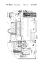
- FIG. 1 is an elevational view of an engine driven alternator unit with part broken away to illustrate the location and interrelationship of the several components including a permanent magnet generator constructed in accordance with the teaching of the present invention
- FIG. 2 is an enlarged vertical section taken generally on line 2--2 of FIG. 1 and illustrates the permanent magnet generator structure
- FIG. 3 is a side view of the rotor shown in FIG. 2 with parts broken away to show the inner surface of the rotor;
- FIG. 4 is an enlarged fragmentary view of the rotor of FIGS. 2-3 and illustrating the securement of the rotor magnets;
- FIG. 5 is a view of a rotor lamination shown in FIGS. 2-4;
- FIG. 6 is a pictorial view of the permanent magnet shown in FIGS. 1 and 2.
- an alternator unit 1 is illustrated adapted to be driven by an internal combustion engine or other suitable prime mover, now shown.
- the alternator unit includes a main power alternator 2 adapted to generate commercially usable power, such as a three phase 480 volt output, for energizing of electrical devices, such as motors, heating units and other high power loads.
- the alternator 2 is a rotating field alternator having a fixed output stator 3 with a rotating field rotor 4 rotatably mounted therein.
- the rotor 4 is supported at the opposite ends of the alternator in suitable precision bearings 5 fixedly mounted as a part of a fixed base structure 6 for supporting of the rotor for high speed rotation.
- the rotor shaft 7 extends from the opposite ends of the alternator 2 with a fan unit 8 secured to the driven end for establishing air flow through the alternator 2 for cooling thereof.
- the opposite end of the shaft 7 extends outwardly of the bearing 5 and terminates within a control box or housing 9.
- An alternator regulator unit 10 (not shown) is housed within the upper portion of the housing 9 and is operational to regulate the alternator output, including the voltage and current levels.
- the rotating field 4 of the alternator 2 is energized from a generator exciter unit 11 secured to the outer end of the alternator shaft 7 with housing 9 for simultaneous rotation and operation.
- the exciter unit 11 includes a rotor 12 fixed to the alternator shaft 7 for rotation within an outer fixed stator unit 12a with the rotating of the field unit 4.
- the exciter output winding 13 is connected to a full wave rectifier circuit board unit 14 secured to the outer end of the shaft for simultaneous rotation with the rotor.
- a permanent magnet generator 15 is mounted between the exciter 11 and the main alternator bearing 5 and includes a rotor 16 secured to the alternator shaft 7.
- An annular fixed stator 17 is mounted by a suitable rigid bracket 18 to the alternator front bracket or end bell 18a.
- the stator 17 includes a single phase or three phase output winding 19, depending upon the design.
- the output of the generator winding 19 is connected to power the regulator 10 and the exciter 11.
- the regulator power supply is maintained independently of the output of the alternator 2 to maintain regulated energization of the exciter 11 and thereby energization of the alternator.
- the present invention is particularly directed to the construction of the permanent magnet generator 15.
- the generator 15 is especially constructed as a small compact unit particulary adapting the mounting as a part of the integrated alternator assembly inboard of the exciter 11 and particularly immediately adjacent the main alternator bearing 5.
- the compact generator 15 is uniquely interrelated to the exciter 11, in that the generator 15 including the stator unit 17 is readily disassembled and removed through the exciter stator bore for servicing and the like.
- the compact unit 15 does not interfere with the longitudinal air flow through the housing 9 and the alternate 2 and thus permits effective cooling of the alternator structure.
- the rotor 16 is a laminated structure including a plurality of like laminations 20.
- the rotor 16 is formed as an annular member having a central opening 21 corresponding to the shaft 7 to which it is affixed by keyed connection 22.
- the rotor 16 is specially constructed as a consequent pole rotor having a plurality of radial teeth 23 and corresponding magnet slots 24. Permanent magnets 25 are secured one each in each slot 24.
- the permanent magnets 25 are similarly radially polarized such as shown in FIG. 2 and establish a flux path 26 through the rotor 16.
- the flux in the pole teeth 23 generate opposite polarity poles to establish the consequent pole operation.
- the rotor 16 thus only requires one-half the total number of magnets generally used in a generator for similar use.
- the permanent magnets 25 are formed of a rare earth material, and preferably iron-boron-neodymium. Such material is readily magnetized to produce a long-life magnet producing a strong magnetic field per unit of material.
- the magnet member of such material is a rather fragile member and should be subjected to minimum mechanical forces.
- the magnets 25 are secured in slots 24 by a suitable adhesive 27 which bonds to the adjacent surfaces of the slots 24 and the magnets 25 to securely mount the magnets in place.
- the magnet 25 is also specially formed to have a radial depth slightly less then the depth of the teeth 23 and the recesses 24.
- the outer surface or face 28 of the magnet 25 is located within the recess and the outer face 29 of the teeth 23 and is thereby protected from mechanical damage.
- each lamination 20 is stamped from a conventional magnetic core material such as 0.022 thick steel in the shape of a generally annular lamination.
- the inner diameter of the annular lamination closely approximates the diameter of the alternator shaft to which the permanent magnet rotor is secured.
- the laminations 20 are assembled in appropriately stacked relation and firmly clamped as an integrated assembly, to form the annular rotor member.
- the stack of laminations 20 are interconnected by a plurality of circumferentially distributed rivet members 30 which projects through the stack of laminations and the opposite rivet ends are swaged as at 31 to securely clamp the lamination into an integrated magnetic core.
- each rotor slot 24 is similarly formed during the stamping of the lamination.
- the slot 24 is generally a rectangular shaped slot having a width somewhat slightly in excess of the width of the adjacent teeth.
- the sidewalls of the slot 24 include an inner portion with substantially straight or inwardly flared walls 32 extending outwardly of the recess base 33 and outer flared sidewalls 34 which flare outwardly from the inner walls 32 by small outwardly curved recesses 35.
- the rivet opening 36 is formed in the lamination of the base portion of each tooth 23.
- the rare earth permanent magnets 25 are formed as elongated solid blocks having a rectangular cross section which generally mate with the slots.
- the width of the magnet 25 is slightly less than the smallest width of the base portion of the slot 24 and the depth of the magnet 25 is also slightly less than the radial depth of the slot 24.
- the magnet is set into the slot 24 with the interposed layer of adhesive 27 between the base 33 and the side walls 32 and 34 of the magnet 25 and the slot 24.
- the adhesive 27 forms a relatively thin bonding layer and is selected to form a firm bond and interconnection to the laminations and to the adjacent base and sidewalls surfaces of the magnet 25.
- an epoxy adhesive produces a particularly satisfactory and reliable attachment of the magnet within the slot for effectively permanently affixing of the magnet in place under all anticipated operating conditions.
- the flared sidewalls 34 of the slots 24 provide a somewhat larger air gap immediately adjacent the outer face 28 of the rotor magnet 25.
- the flared portions minimize the leakage flux immediately adjacent the side edges of the magnets and contributes to the desired flux movement from the magnets 25 to the stator 17.
- the flared portions within the slots also provide a somewhat increased spaced filled with the epoxy adhesive and contribute to a strong adhesive bonding of the permanent magnets within the rotor slots.
- the rotor was formed with dimensions in inches approximately as follows.
- the outer diameter of the rotor was 4.570 inches and the inner diameter of 2.70.
- the rotor had 10 equicircumferentially spaced teeth.
- Each slot had the inner width of 0.630 inches adjacent the base portion and flared outwardly therefrom to a maximum dimension of 0.820 inches.
- the total depth of the inner portion adjacent the base was 0.225 inches and the flared portion 0.269 inches.
- the sidewalls were joined to a flat base by generally semicircular recesses.
- a shaft key 37 was formed as shown with a width of about 0.745.
- the shaft 7 is formed with a machined surface to which the rotor 16 is secured.
- the shaft is provided with a connecting keyway 38 and the permanent magnet rotor is formed with the corresponding mating key 37.
- the key is shown with a significant circumferential dimension to provide a firm strong interlock between the rotor and the shaft.
- the stator core 17 of the permanent magnet generator 17 is formed as a generally square stator unit having a circular opening within which the rotor is rotatably mounted.
- the single or three phase winding 17 is wound within the slotted stator for generating the appropriate output voltage and current for powering of a voltage regulator or the like.
- the stator core 17 is a laminated structure and constructed to the form having a relatively square peripheral configuration. The enlarged corner portions of the core are apertured to receive the mounting bolts.
- the main exciter 11 is mounted outboard of the permanent magnet generator and consists of a fixed annular stator 12a fixedly mounted to the front bracket 18a.
- An exciter rotor 12 is secured to the alternator shaft.
- the alternator shaft 7 terminates just outwardly of the exciter.
- a full wave rectifier board 14 is secured to the end of the shaft.
- the full wave rectifier has its input connected to the output of the exciter and its output connected by suitable leads to the rotating field of the main alternator.
- the field of the exciter is stationary and the excitation thereof is controlled by the regulator to control the output of the exciter and thereby the excitation of the main rotating field of the alternator.
- the permanent magnet generator output is connected from the stationary output single or three phase output winding to power the voltage regulator for controlling the exciter and thereby the main alternator.
- a small compact permanent magnet alternator is highly desirable to provide a compact overall alternator assembly.
- the main alternator requires a forced cooling system and a fan means is generally connected to the opposite end of the shaft opposite the engine drive.
- a compact overall assembly permits proper movement of air through the main alternator.
Landscapes
- Engineering & Computer Science (AREA)
- Power Engineering (AREA)
- Synchronous Machinery (AREA)
- Permanent Field Magnets Of Synchronous Machinery (AREA)
Abstract
A permanent magnet generator has a laminated rotor mounted to the driven shaft of a power alternator. The rotor is cylindrical and includes 10 circumferentially distributed elongated axial slots and 10 rotor teeth. Iron-boron-neodymium rare earth magnets are secured within each of the slots, radially and similarly polarized. The magnet and teeth define a consequent 20 pole rotor with a minimum number of magnets. The rare earth magnets are epoxy bonded within each of the corresponding slots. Each slot has a rectangular cross-section with slightly flared sides. The epoxy extends between the recess surfaces and the magnets. The flared sides improve the flux distribution. The outer radial ends of the magnets spaced inwardly of the rotor teeth prevent mechaical damage to the magnets. The outside maximum dimension of the PMG stator is slightly less than the inner diameter of the exciter stator for convenient removal through the bore of the exciter.
Description
This invention relates to a permanent magnet generator apparatus and particularly to such a generator apparatus adapted for energizing of a voltage regulator of an regulated alternator system.
Permanent magnet generators have been available for many years. The generators are of an advantageous construction and may employ permanent magnets, limiting the necessity for a separate power supply for excitation of the generator. The advantage associated with permanent magnets has been significantly increased with the advance in the construction and availability of materials for permanent magnets. Various rare earth metals provide high strength permanent magnets having a long magnetic life. Permanent magnet generators have generally been more or less restricted to precision generators and particularly generators in which the mechanical and centrifugal forces on the magnets are not severe. Rare earth magnets are particularly brittle and particularly subject to mechanical damage. The holding means on the magnets, particularly where large forces are present, require careful mechanical construction. The constructional limitations have limited the use in certain applications.
For example, relatively large alternators which are driven by engines, turbines and other prime movers are widely used in industry to provide an alternating current power supply. Three-phase alternators providing voltages of 240/480 volts are commonly commercially marketed. Such alternators universally include a regulator for regulation of the voltage, current and/or frequency. The regulator requires a logic power supply.
The alternators are also provided with appropriate excitation from an exciter generator which is coupled to the common shaft with the alternator. The output of the exciter is rectified and coupled to the field winding of the alternator. The regulator and exciter may be powered through a feedback coupling to the output of the alternator. In many applications, a separate power supply is advantageously used for powering the voltage regulator and the exciter. Permanent magnet generators are adapted to such use and have been used commercially in such structures. In such construction, the permanent magnet rotor of the generator is conventionally mounted to the common shaft unit with the alternator field rotor and the exciter rotor winding. A stationary three phase output winding is connected through a suitable rectifying and signal processing circuit to provide the necessary power to the voltage regulator and to the exciter. The permanent magnet generator of a conventional construction is a reasonably large heavy device and has been mounted outboard of the exciter. In at least one instance, the alternator has been mounted inboard of the exciter, that is, between the exciter and the main alternator. The permanent magnet generators have generally applied relatively large permanent magnet members secured in side-by-side relation circumferentially about the rotor base, and with adjacent magnets oppositely polarized. A suitable mechanical keeper in the form of a heavy band is clamped about the magnets to hold the magnets in place. This construction is necessary because of the large centrifugal forces on the magnets and the requirement of establishing a stable and reliable high force support of the magnets.
Although such systems have been used in commercial devices and provide a satisfactory alternator operation with the general advantages provided by the separate power supply, the permanent magnet generator is relatively large and presents certain difficulties from the standpoint of suitable construction not only of the generator but the mounting of the generator within and as a part of the main alternator system. Although a permanent magnet generator using rare earth permanent magnets would appear to be advantageously used, the nature of such magnets and the large forces and environment in an alternator makes the use of such magnets difficult, and the present inventor knows of no such use.
There is a distinct need for a small, compact permanent magnet generator which can be applied to and integrated into an alternator unit. Such permanent magnet generator may of course also advantageously be applied to other applications.
The permanent magnet generator must be particularly adapted to an economic commercial implementation, generally requiring the use of mass production technology which is presently commercially available.
The present invention is particularly directed to a permanent magnet generator producing a greater power output for any given size and which can be constructed with a compact high speed rotor, and particularly such a generator which can be directly driven as an integrated part of a regulated alternator adapted to produce commercially demanded voltages and currents.
Generally in accordance with the teaching of the present invention, the permanent magnet generator is formed with a cylindrical rotor adapted to be driven from a suitable prime mover such as that used in driving a power alternator. The cylindrical rotor includes circumferentially distributed enlongated slots separated by corresponding rotor teeth. The rotor is preferably a laminated assembly formed of magnetic material such as a magnetic steel presently used in stator and rotor construction. In accordance with the present invention, rare earth magnets are secured within each of the slots and radially polarized to define permanent magnetic poles, with the flux passing through the adjacent rotor and stator cores and the air gaps therebetween. The permanent magnets are all similarly polarized, with the flux passing through the adjacent magnetic core teeth generating opposite polarized poles, and defining a consequent pole rotor unit. The consequent pole construction of the generator thus uniquely reduces the number of magnets required and adapts the rotor to the use of the rare earth magnets in producing a relatively small compact unit.
In a preferred unique structure, the rare earth magnets are adhesively bonded within each of the corresponding slots to effectively permanently affix the magnets in place. The adhesive bonding eliminates the stresses placed on the magnets normally encountered with a mechanical keeper or the like. The inventor has found that an appropriate adhesive bonding of the magnets permits the retention of the magnets at the high speed operation encountered in the conventional regulated engine driven alternator systems.
The permanent magnets are fabricated from a suitable magnetic rare earth metal which is known to provide a strong permanent magnetic field per unit of volume or size. The present inventor has discovered that iron-boron-neodymium provides an optimum material. The iron-boron-neodymium produces a desired high strength magnetic field with a minimum cost. The material can be conveniently mass produced in the desired rectangular elongated bar-like shape and highly magnetized to produce a high strength magnet. The formed magnets are adapted to adhesive bonding within the several rotor slots. The outer surface and face of each magnet is spaced slightly inwardly from the outer surface of the rotor teeth, thereby protecting the relatively fragile magnets from mechanical damage during handling and operation.
The rare earth permanent magnets permit reduction in the overall diameter and size of the generator and particularly the rotor. Consequently, the centrifugal forces on the magnets are somewhat less than that which would be encountered in the permanent magnet generator heretofore used as a part of an integrated regulated alternator system.
In the preferred construction of the generator unit for an alternator control, the outside maximum dimension of the stator of the generator was slightly less than the inner diameter of the exciter stator. This permits mounting of the generator inboard of the exciter with the convenient removal of the permanent magnet generator through the bore of the exciter for service if necessary.
The present invention thus provides a significantly improved generator where size is significant for any given power output. The rotor is readily constructed using present day materials, as well as forming and assembly technology to permit commercial implementation of the invention.
The drawings furnished herewith generally illustrate the best mode presently contemplated for the invention and is described hereinafter.
In the drawings:
FIG. 1 is an elevational view of an engine driven alternator unit with part broken away to illustrate the location and interrelationship of the several components including a permanent magnet generator constructed in accordance with the teaching of the present invention;
FIG. 2 is an enlarged vertical section taken generally on line 2--2 of FIG. 1 and illustrates the permanent magnet generator structure;
FIG. 3 is a side view of the rotor shown in FIG. 2 with parts broken away to show the inner surface of the rotor;
FIG. 4 is an enlarged fragmentary view of the rotor of FIGS. 2-3 and illustrating the securement of the rotor magnets;
FIG. 5 is a view of a rotor lamination shown in FIGS. 2-4; and
FIG. 6 is a pictorial view of the permanent magnet shown in FIGS. 1 and 2.
Referring to the drawing and particularly to FIG. 1, an alternator unit 1 is illustrated adapted to be driven by an internal combustion engine or other suitable prime mover, now shown. The alternator unit includes a main power alternator 2 adapted to generate commercially usable power, such as a three phase 480 volt output, for energizing of electrical devices, such as motors, heating units and other high power loads. The alternator 2 is a rotating field alternator having a fixed output stator 3 with a rotating field rotor 4 rotatably mounted therein. The rotor 4 is supported at the opposite ends of the alternator in suitable precision bearings 5 fixedly mounted as a part of a fixed base structure 6 for supporting of the rotor for high speed rotation. The rotor shaft 7 extends from the opposite ends of the alternator 2 with a fan unit 8 secured to the driven end for establishing air flow through the alternator 2 for cooling thereof. The opposite end of the shaft 7 extends outwardly of the bearing 5 and terminates within a control box or housing 9. An alternator regulator unit 10 (not shown) is housed within the upper portion of the housing 9 and is operational to regulate the alternator output, including the voltage and current levels. The rotating field 4 of the alternator 2 is energized from a generator exciter unit 11 secured to the outer end of the alternator shaft 7 with housing 9 for simultaneous rotation and operation. The exciter unit 11 includes a rotor 12 fixed to the alternator shaft 7 for rotation within an outer fixed stator unit 12a with the rotating of the field unit 4. The exciter output winding 13 is connected to a full wave rectifier circuit board unit 14 secured to the outer end of the shaft for simultaneous rotation with the rotor.
A permanent magnet generator 15 is mounted between the exciter 11 and the main alternator bearing 5 and includes a rotor 16 secured to the alternator shaft 7. An annular fixed stator 17 is mounted by a suitable rigid bracket 18 to the alternator front bracket or end bell 18a. The stator 17 includes a single phase or three phase output winding 19, depending upon the design. The output of the generator winding 19 is connected to power the regulator 10 and the exciter 11. Thus the regulator power supply is maintained independently of the output of the alternator 2 to maintain regulated energization of the exciter 11 and thereby energization of the alternator.
The present invention is particularly directed to the construction of the permanent magnet generator 15. As more fully developed presently, the generator 15 is especially constructed as a small compact unit particulary adapting the mounting as a part of the integrated alternator assembly inboard of the exciter 11 and particularly immediately adjacent the main alternator bearing 5. The compact generator 15 is uniquely interrelated to the exciter 11, in that the generator 15 including the stator unit 17 is readily disassembled and removed through the exciter stator bore for servicing and the like. The compact unit 15 does not interfere with the longitudinal air flow through the housing 9 and the alternate 2 and thus permits effective cooling of the alternator structure.
Referring to FIGS. 2-5, the rotor 16 is a laminated structure including a plurality of like laminations 20. The rotor 16 is formed as an annular member having a central opening 21 corresponding to the shaft 7 to which it is affixed by keyed connection 22. The rotor 16 is specially constructed as a consequent pole rotor having a plurality of radial teeth 23 and corresponding magnet slots 24. Permanent magnets 25 are secured one each in each slot 24. The permanent magnets 25 are similarly radially polarized such as shown in FIG. 2 and establish a flux path 26 through the rotor 16. The flux in the pole teeth 23 generate opposite polarity poles to establish the consequent pole operation. The rotor 16 thus only requires one-half the total number of magnets generally used in a generator for similar use. The permanent magnets 25 are formed of a rare earth material, and preferably iron-boron-neodymium. Such material is readily magnetized to produce a long-life magnet producing a strong magnetic field per unit of material. The magnet member of such material is a rather fragile member and should be subjected to minimum mechanical forces. In accordance with a preferred construction, the magnets 25 are secured in slots 24 by a suitable adhesive 27 which bonds to the adjacent surfaces of the slots 24 and the magnets 25 to securely mount the magnets in place.
The magnet 25 is also specially formed to have a radial depth slightly less then the depth of the teeth 23 and the recesses 24. The outer surface or face 28 of the magnet 25 is located within the recess and the outer face 29 of the teeth 23 and is thereby protected from mechanical damage.
More particularly, each lamination 20 is stamped from a conventional magnetic core material such as 0.022 thick steel in the shape of a generally annular lamination. The inner diameter of the annular lamination closely approximates the diameter of the alternator shaft to which the permanent magnet rotor is secured.
The laminations 20 are assembled in appropriately stacked relation and firmly clamped as an integrated assembly, to form the annular rotor member. In the illustrated embodiment of the invention, the stack of laminations 20 are interconnected by a plurality of circumferentially distributed rivet members 30 which projects through the stack of laminations and the opposite rivet ends are swaged as at 31 to securely clamp the lamination into an integrated magnetic core.
As more clearly shown in FIG. 5, each rotor slot 24 is similarly formed during the stamping of the lamination. The slot 24 is generally a rectangular shaped slot having a width somewhat slightly in excess of the width of the adjacent teeth. The sidewalls of the slot 24 include an inner portion with substantially straight or inwardly flared walls 32 extending outwardly of the recess base 33 and outer flared sidewalls 34 which flare outwardly from the inner walls 32 by small outwardly curved recesses 35. The rivet opening 36 is formed in the lamination of the base portion of each tooth 23.
The rare earth permanent magnets 25 are formed as elongated solid blocks having a rectangular cross section which generally mate with the slots. The width of the magnet 25 is slightly less than the smallest width of the base portion of the slot 24 and the depth of the magnet 25 is also slightly less than the radial depth of the slot 24. The magnet is set into the slot 24 with the interposed layer of adhesive 27 between the base 33 and the side walls 32 and 34 of the magnet 25 and the slot 24. The adhesive 27 forms a relatively thin bonding layer and is selected to form a firm bond and interconnection to the laminations and to the adjacent base and sidewalls surfaces of the magnet 25.
Although any suitable adhesive can be applied, the inventor has found an epoxy adhesive produces a particularly satisfactory and reliable attachment of the magnet within the slot for effectively permanently affixing of the magnet in place under all anticipated operating conditions.
The flared sidewalls 34 of the slots 24 provide a somewhat larger air gap immediately adjacent the outer face 28 of the rotor magnet 25. The flared portions minimize the leakage flux immediately adjacent the side edges of the magnets and contributes to the desired flux movement from the magnets 25 to the stator 17.
The flared portions within the slots also provide a somewhat increased spaced filled with the epoxy adhesive and contribute to a strong adhesive bonding of the permanent magnets within the rotor slots.
Thus in a typical embodiment of the invention, the rotor was formed with dimensions in inches approximately as follows.
The outer diameter of the rotor was 4.570 inches and the inner diameter of 2.70. The rotor had 10 equicircumferentially spaced teeth. Each slot had the inner width of 0.630 inches adjacent the base portion and flared outwardly therefrom to a maximum dimension of 0.820 inches. The total depth of the inner portion adjacent the base was 0.225 inches and the flared portion 0.269 inches. The sidewalls were joined to a flat base by generally semicircular recesses. A shaft key 37 was formed as shown with a width of about 0.745.
The shaft 7 is formed with a machined surface to which the rotor 16 is secured. The shaft is provided with a connecting keyway 38 and the permanent magnet rotor is formed with the corresponding mating key 37. The key is shown with a significant circumferential dimension to provide a firm strong interlock between the rotor and the shaft.
The stator core 17 of the permanent magnet generator 17 is formed as a generally square stator unit having a circular opening within which the rotor is rotatably mounted. The single or three phase winding 17 is wound within the slotted stator for generating the appropriate output voltage and current for powering of a voltage regulator or the like. The stator core 17 is a laminated structure and constructed to the form having a relatively square peripheral configuration. The enlarged corner portions of the core are apertured to receive the mounting bolts.
The main exciter 11 is mounted outboard of the permanent magnet generator and consists of a fixed annular stator 12a fixedly mounted to the front bracket 18a. An exciter rotor 12 is secured to the alternator shaft. The alternator shaft 7 terminates just outwardly of the exciter. A full wave rectifier board 14 is secured to the end of the shaft. The full wave rectifier has its input connected to the output of the exciter and its output connected by suitable leads to the rotating field of the main alternator. The field of the exciter is stationary and the excitation thereof is controlled by the regulator to control the output of the exciter and thereby the excitation of the main rotating field of the alternator.
The permanent magnet generator output is connected from the stationary output single or three phase output winding to power the voltage regulator for controlling the exciter and thereby the main alternator.
A small compact permanent magnet alternator is highly desirable to provide a compact overall alternator assembly. The main alternator requires a forced cooling system and a fan means is generally connected to the opposite end of the shaft opposite the engine drive. A compact overall assembly permits proper movement of air through the main alternator.
Various modes of carrying out the invention are contemplated as being within the scope of the following claims particularly pointing out and distinctly claiming the subject matter which is regarded as the invention.
Claims (15)
1. A permanent magnet generator rotor adapted to be mounted within a stator having a cylindrical surface, comprising a cylindrical rotor core having a plurality of circumferentially spaced rotor poles having cylindrical outer surfaces with a diameter slightly less than said stator and defining slots extending longitudinally of the rotor core, each of said slots having an essentially constant circumferential width throughout the inner portion of the slot and with the outer portions of the slot flared outwardly, a permanent magnet formed of a rare earth magnetic material secured within each of said slots with a radially outer exposed surface extended over the width of said inner portion of the slots, said radially outer exposed surface of each of said magnets totally located radially inwardly of the cylindrical outer surface of the rotor core over the complete width of said slot by a depth only required to prevent engagement with the stator cylindrical surface.
2. A permanent magnet generator rotor adapted to be mounted within a stator having a cylindrical surface, comprising a cylindrical rotor core having a plurality of circumferentially spaced rotor poles having cylindrical outer surfaces with a diameter slightly less than said stator and defining slots extending longitudinally of the rotor core, each of said slots having an essentially constant circumferential width throughout the slot, a permanent magnet formed of a rare earth magnetic material secured within each of said slots with a radially outer exposed surface extended over the width of the slot, said radially outer exposed surface of each of said magnets totally located radially inwardly of the cylindrical outer surface of the rotor core over the complete width of said slot by a depth only required to prevent engagement with the stator cylindrical surface, wherein each of said slots includes a substantially flat base and sidewalls including a first inner portion and a second outer portion flaring outwardly and laterally, said magnets having parallel flat sidewalls and a width slightly less than the width of said slot.
3. A permanent magnet generator rotor adapted to be mounted within a stator having a cylindrical surface, comprising a cylindrical rotor core having a plurality of circumferentially spaced rotor poles having cylindrical outer surfaces with a diameter slightly less than said stator and defining slots extending longitudinally of the rotor core, each of said slots having an essentially constant circumferential width throughout the slot, a permanent magnet formed of a rare earth magnetic material secured within each of said slots with a radially outer exposed surface extended over the width of the slot, said radially outer exposed surface of each of said magnets totally located radially inwardly of the cylindrical outer surface of the rotor core over the complete width of said slot by a depth only required to prevent engagement with the stator cylindrical surface, including an adhesive interposed between said magnets and all opposed surfaces of said slots, said adhesive securing said magnets in said slots.
4. The generator rotor of claim 3 wherein said rotor poles have a circumferential width less than that of said slots.
5. The generator rotor of claim 4 wherein the sidewalls of said poles and slots have an outer portion which flares circumferentially to produce an enlarged opening to said slot.
6. The generator rotor of claim 5 wherein said rare earth magnetic material is iron-boron-neodymium.
7. The generator rotor of claim 3 wherein said rare earth magnetic material is iron-baron-neodymium.
8. A permanent magnet generator rotor apparatus, comprising a cylindrical rotor core having a plurality of circumferentially spaced outwardly flared surface slots extending axially of the rotor core, a rectangular permanent magnet secured within each of said slots, each of said magnets being a solid magnet formed of iron-boron-neodymium and being similarly located radially inwardly of the outer cylindrical surface of the rotor core, and including an adhesive in each slot interposed between said magnets and opposed surfaces of said slot, said adhesive forming the sole support of said magnets in said rotor core.
9. A regulated alternator unit comprising a support base structure, an alternator having a rotating field rotor including a shaft, a bearing means secured to one end of said alternator, said shaft extending from said bearing means, a permanent magnet generator having a rotor secured to said shaft immediately outboard of said bearing means and a stator mounted to said base structure, said rotor having a plurality of circumferentially spaced surface slots extending longitudinally of the rotor, a permanent magnet formed of a rare earth magnetic material secured within each of said slots, and an exciter having a rotor secured to the shaft outboard of said generator and having a exciter stator secured to said base structure, said exciter stator having a rotor opening of a diameter in excess of the maximum width of said stator of said generator.
10. The regulated alternator unit of claim 9 wherein an epoxy adhesive is interposed between said magnets and opposed surfaces of said slots, said epoxy adhesive forming the sole support of said magnets in said rotor.
11. A regulated alternator unit comprising an alternator having a rotating field rotor including a shaft and an excitation winding unit, a permanent magnet generator having a permanent magnet rotor secured to said shaft, said rotor having a lamination core of single piece laminations and having a plurality of circumferentially spaced rotor teeth defining surface slots extending axially of the rotor, a permanent magnet secured within each of said slots and said magnets having the same radial polarization and exposed outer surfaces and with the adjacent rotor teeth defining a consequent pole generator, said generator having an output winding connected to said excitation winding unit to excite said alternator.
12. The regulated alternator unit of claim 11 wherein said magnets have an outer surface spaced radially inwardly of the outer cylindrical surface of the rotor teeth.
13. The regulated alternator unit of claim 11 wherein an adhesive is interposed between said magnets and opposed surfaces of said slots, said adhesive supporting said magnets in said rotor.
14. A permanent magnet generator rotor, comprising a cylindrical lamination rotor core of single piece laminations having a plurality of circumferentially spaced rotor poles defining slots extending axially of the rotor core, and permanent magnets secured within each of said slots and said magnets each having the same radial polarization and exposed outer surfaces to form a consequent pole rotor for a permanent magnet rotor machine, including an adhesive interposed between said magnets and opposed surfaces of said slots and securing said magnets in said slots.
15. The regulated alternator unit of claim 9 wherein said magnets have an outer surface spaced radially inwardly of the outer cylindrical surface of the rotor.
Priority Applications (1)
| Application Number | Priority Date | Filing Date | Title |
|---|---|---|---|
| US06/897,133 US4777397A (en) | 1986-08-15 | 1986-08-15 | Permanent magnet generator apparatus including a consequent pole rotor |
Applications Claiming Priority (1)
| Application Number | Priority Date | Filing Date | Title |
|---|---|---|---|
| US06/897,133 US4777397A (en) | 1986-08-15 | 1986-08-15 | Permanent magnet generator apparatus including a consequent pole rotor |
Publications (1)
| Publication Number | Publication Date |
|---|---|
| US4777397A true US4777397A (en) | 1988-10-11 |
Family
ID=25407387
Family Applications (1)
| Application Number | Title | Priority Date | Filing Date |
|---|---|---|---|
| US06/897,133 Expired - Lifetime US4777397A (en) | 1986-08-15 | 1986-08-15 | Permanent magnet generator apparatus including a consequent pole rotor |
Country Status (1)
| Country | Link |
|---|---|
| US (1) | US4777397A (en) |
Cited By (55)
| Publication number | Priority date | Publication date | Assignee | Title |
|---|---|---|---|---|
| US4987330A (en) * | 1990-01-16 | 1991-01-22 | General Motors Corporation | Rotor lamination assembly for a dynamoelectric machine |
| US5177391A (en) * | 1990-03-14 | 1993-01-05 | Nippondenso Co., Ltd. | Power generating apparatus |
| US5397975A (en) * | 1993-06-14 | 1995-03-14 | Ecoair Corp. | Hybrid alternator |
| US5502368A (en) * | 1994-06-06 | 1996-03-26 | Ecoair Corp. | Hybrid alternator with voltage regulator |
| US5581139A (en) * | 1993-08-25 | 1996-12-03 | Ipalco B.V. | Magnetic hysteresis clutch |
| US5600194A (en) * | 1993-08-25 | 1997-02-04 | Ipalco B.V. | Magnetic hysteresis clutch |
| US5693995A (en) * | 1993-06-14 | 1997-12-02 | Ecoair Corp. | Hybrid alternator |
| US5714823A (en) * | 1994-08-29 | 1998-02-03 | Sundstrand Corporation | Quasi regulated permanent magnet generator |
| US5747909A (en) * | 1996-03-14 | 1998-05-05 | Ecoair Corp. | Hybrid alternator |
| US5753989A (en) * | 1993-06-14 | 1998-05-19 | Ecoair Corp. | Hybrid alternator |
| EP0844722A1 (en) * | 1996-11-25 | 1998-05-27 | Magnet-Motor Gesellschaft für magnetmotorische Technik mbH | Permanent magnet excited electric machine with rotor flux closing parts |
| WO1998029938A3 (en) * | 1996-12-30 | 1998-10-15 | Arcelik As | A high performance electric motor |
| US5886441A (en) * | 1993-02-15 | 1999-03-23 | Fanuc, Ltd. | Rotor for synchronous motor |
| WO2000028642A1 (en) * | 1998-11-12 | 2000-05-18 | Emerson Electric Co. | Polygonal shaft hole rotor |
| US6075306A (en) * | 1998-12-30 | 2000-06-13 | Mfm Technology L.L.C. | Laminated rotor for permanent magnet brushless motors |
| US6097124A (en) * | 1997-10-23 | 2000-08-01 | Satcon Technology Corporation | Hybrid permanent magnet/homopolar generator and motor |
| US6150747A (en) * | 1999-05-04 | 2000-11-21 | Electric Boat Corporation | Composite stator and rotor for an electric motor |
| US6455975B1 (en) | 1999-12-03 | 2002-09-24 | Pacific Scientific Electro Kinetics Division | Regulated permanent magnet generator |
| US6531799B1 (en) | 1999-12-20 | 2003-03-11 | Ford Global Technologies, Inc. | Hybrid electric machine with two rotors, permanent magnet poles and controllable field current |
| DE10217977A1 (en) * | 2002-04-23 | 2003-11-27 | Oswald Elektromotoren Gmbh | Rotor e.g. for synchronous machine, has body with several permanent magnets on peripheral surface and covered by holding cover joined to body between permanent magnets in peripheral direction |
| EP1376831A2 (en) * | 2002-06-27 | 2004-01-02 | Aisin Aw Co., Ltd. | Rotor for permanent magnet variable reluctance motor |
| US20040047090A1 (en) * | 2000-11-11 | 2004-03-11 | Susanne Evans | Armature with coated laminate bundle |
| US6734596B1 (en) * | 2003-01-06 | 2004-05-11 | Unique Product & Design Co., Ltd. | Assembling type rotor structure of brushless motor |
| US20060087123A1 (en) * | 2004-10-22 | 2006-04-27 | Stout David E | Dual-rotor, single input/output starter-generator |
| US20070296298A1 (en) * | 2006-05-10 | 2007-12-27 | Jones Robert M | Electric machine having segmented stator |
| US7471000B1 (en) | 2006-04-25 | 2008-12-30 | Ruiz Rafael J | Portable battery charger powered by internal combustion engine |
| US20100013350A1 (en) * | 2007-01-29 | 2010-01-21 | Toyota Jidosha Kabushiki Kaisha | Rotor and rotating electric machine with the rotor |
| US20100013343A1 (en) * | 2006-12-18 | 2010-01-21 | Dachuan Bi | Constant frequency and locked phase generator adaptable to variable torque |
| US20100253160A1 (en) * | 2009-04-03 | 2010-10-07 | Robert M. Jones | Over-Molded Liquid Cooled Three-Stack Motor |
| CN101882826A (en) * | 2009-05-06 | 2010-11-10 | 哈米尔顿森德斯特兰德公司 | The axial retention of p-m rotor in the high-speed engine |
| FR2945683A1 (en) * | 2009-05-18 | 2010-11-19 | Erneo | VERNIER MACHINE WITH INSIDE MAGNETS. |
| US20100308680A1 (en) * | 2009-05-20 | 2010-12-09 | Asmo Co., Ltd. | Rotor and Motor |
| US7884522B1 (en) | 2004-10-25 | 2011-02-08 | Novatorque, Inc. | Stator and rotor-stator structures for electrodynamic machines |
| US7982350B2 (en) | 2004-10-25 | 2011-07-19 | Novatorque, Inc. | Conical magnets and rotor-stator structures for electrodynamic machines |
| DE102010022702A1 (en) * | 2010-06-04 | 2011-12-08 | Wilo Se | Rotor for synchronous motor, has permanent magnets slid into parallel pockets and made from punched metal sheets, where magnets are clamped in pockets in force-fit manner by shape of window edges |
| JP2012034565A (en) * | 2010-12-27 | 2012-02-16 | Yaskawa Electric Corp | Rotating electric machine and wind-force power generating system |
| US8283832B2 (en) | 2004-10-25 | 2012-10-09 | Novatorque, Inc. | Sculpted field pole members and methods of forming the same for electrodynamic machines |
| CN102738923A (en) * | 2011-03-30 | 2012-10-17 | 阿斯莫有限公司 | Motor and electric pump |
| US8330316B2 (en) | 2011-03-09 | 2012-12-11 | Novatorque, Inc. | Rotor-stator structures including boost magnet structures for magnetic regions in rotor assemblies disposed external to boundaries of conically-shaped spaces |
| US8471425B2 (en) | 2011-03-09 | 2013-06-25 | Novatorque, Inc. | Rotor-stator structures including boost magnet structures for magnetic regions having angled confronting surfaces in rotor assemblies |
| US20130162086A1 (en) * | 2011-12-23 | 2013-06-27 | National Cheng Kung University | Permanent magnet apparatus |
| US8543365B1 (en) | 2004-10-25 | 2013-09-24 | Novatorque, Inc. | Computer-readable medium, a method and an apparatus for designing and simulating electrodynamic machines implementing conical and cylindrical magnets |
| US20140049124A1 (en) * | 2012-08-20 | 2014-02-20 | Rensselaer Polytechnic Institute | Double-rotor flux-switching machine |
| US20140103770A1 (en) * | 2012-10-15 | 2014-04-17 | Rbc Manufacturing Corporation | Permanent magnet rotor and methods thereof |
| US9093874B2 (en) | 2004-10-25 | 2015-07-28 | Novatorque, Inc. | Sculpted field pole members and methods of forming the same for electrodynamic machines |
| US9130426B2 (en) | 2011-10-31 | 2015-09-08 | Regal Beloit America, Inc. | Permanent magnet rotors and methods of assembling the same |
| DE102004036691B4 (en) * | 2003-07-31 | 2015-11-05 | Kabushiki Kaisha Toshiba | Rotor for a rotating machine of a reluctance type |
| WO2016155727A1 (en) * | 2015-04-02 | 2016-10-06 | Bühler Motor GmbH | Permanent-magnet rotor |
| US9610596B2 (en) | 2012-10-01 | 2017-04-04 | Graco Minnesota Inc. | Alternator for electrostatic spray gun |
| US9752550B2 (en) | 2013-10-10 | 2017-09-05 | Kirloskar Energen Private Limited | In-pipe turbine and hydro-electric power generation system with separable housing and detachable vane arrangements |
| US9882440B2 (en) | 2012-10-15 | 2018-01-30 | Regal Beloit America, Inc. | Radially embedded permanent magnet rotor and methods thereof |
| US9923423B2 (en) | 2012-10-15 | 2018-03-20 | Regal Beloit America, Inc. | Radially embedded permanent magnet rotor and methods thereof |
| EA037210B1 (en) * | 2017-11-29 | 2021-02-19 | Открытое акционерное общество "Межгосударственная Корпорация Развития" | Electric motor |
| US20220109362A1 (en) * | 2019-02-04 | 2022-04-07 | Gerald William Rowley | Magnetic torque convertor for utility applications |
| WO2023166876A1 (en) * | 2022-03-04 | 2023-09-07 | 三菱電機株式会社 | Rotating electric machine |
Citations (18)
| Publication number | Priority date | Publication date | Assignee | Title |
|---|---|---|---|---|
| US2485474A (en) * | 1947-01-11 | 1949-10-18 | Keefe And Merritt Company O | Permanent magnet rotor |
| US2754440A (en) * | 1952-06-16 | 1956-07-10 | Ruckstell Corp | Rotor construction and method of magnetizing the same |
| US2756356A (en) * | 1953-09-16 | 1956-07-24 | Globe Union Inc | Field magnet unit for flywheel magnetos |
| US3836802A (en) * | 1973-09-06 | 1974-09-17 | Gen Electric | Permanent magnet motor |
| US3858308A (en) * | 1973-06-22 | 1975-01-07 | Bendix Corp | Process for making a rotor assembly |
| US3900749A (en) * | 1974-04-02 | 1975-08-19 | Hmw Industries | Permanent magnet generator |
| US3979821A (en) * | 1975-05-09 | 1976-09-14 | Kollmorgen Corporation | Method of manufacturing rare earth permanent magnet rotor |
| US4025840A (en) * | 1975-04-09 | 1977-05-24 | General Electric Company | Permanent magnet generator with output power adjustment by means of magnetic shims |
| US4139790A (en) * | 1977-08-31 | 1979-02-13 | Reliance Electric Company | Direct axis aiding permanent magnets for a laminated synchronous motor rotor |
| US4167684A (en) * | 1977-12-15 | 1979-09-11 | Kelly Donald A | Magnetic torque multiplier |
| US4302693A (en) * | 1978-12-26 | 1981-11-24 | The Garrett Corporation | Wedge shaped permanent magnet rotor assembly with magnet cushions |
| US4433261A (en) * | 1982-03-24 | 1984-02-21 | Kabushiki Kaisha Okuma Tekkosho | Rotor for permanent magnet type synchronous motors |
| US4504755A (en) * | 1983-11-03 | 1985-03-12 | Kollmorgen Technologies Corporation | Rotor reluctance notch for cogging control |
| US4533891A (en) * | 1983-04-07 | 1985-08-06 | Pneumo Corporation | Limited angle torque motor |
| US4547713A (en) * | 1982-11-05 | 1985-10-15 | Kollmorgen Technologies Corporation | Toroidally wound brushless DC motor |
| US4549341A (en) * | 1983-07-19 | 1985-10-29 | The Garrett Corporation | Method for producing a permanent magnet rotor |
| US4568642A (en) * | 1984-12-24 | 1986-02-04 | Advanced Dental Applications Corporation | Quiet dental drill |
| US4631435A (en) * | 1985-12-18 | 1986-12-23 | The Garrett Corporation | Consequent pole permanent magnet rotor |
-
1986
- 1986-08-15 US US06/897,133 patent/US4777397A/en not_active Expired - Lifetime
Patent Citations (18)
| Publication number | Priority date | Publication date | Assignee | Title |
|---|---|---|---|---|
| US2485474A (en) * | 1947-01-11 | 1949-10-18 | Keefe And Merritt Company O | Permanent magnet rotor |
| US2754440A (en) * | 1952-06-16 | 1956-07-10 | Ruckstell Corp | Rotor construction and method of magnetizing the same |
| US2756356A (en) * | 1953-09-16 | 1956-07-24 | Globe Union Inc | Field magnet unit for flywheel magnetos |
| US3858308A (en) * | 1973-06-22 | 1975-01-07 | Bendix Corp | Process for making a rotor assembly |
| US3836802A (en) * | 1973-09-06 | 1974-09-17 | Gen Electric | Permanent magnet motor |
| US3900749A (en) * | 1974-04-02 | 1975-08-19 | Hmw Industries | Permanent magnet generator |
| US4025840A (en) * | 1975-04-09 | 1977-05-24 | General Electric Company | Permanent magnet generator with output power adjustment by means of magnetic shims |
| US3979821A (en) * | 1975-05-09 | 1976-09-14 | Kollmorgen Corporation | Method of manufacturing rare earth permanent magnet rotor |
| US4139790A (en) * | 1977-08-31 | 1979-02-13 | Reliance Electric Company | Direct axis aiding permanent magnets for a laminated synchronous motor rotor |
| US4167684A (en) * | 1977-12-15 | 1979-09-11 | Kelly Donald A | Magnetic torque multiplier |
| US4302693A (en) * | 1978-12-26 | 1981-11-24 | The Garrett Corporation | Wedge shaped permanent magnet rotor assembly with magnet cushions |
| US4433261A (en) * | 1982-03-24 | 1984-02-21 | Kabushiki Kaisha Okuma Tekkosho | Rotor for permanent magnet type synchronous motors |
| US4547713A (en) * | 1982-11-05 | 1985-10-15 | Kollmorgen Technologies Corporation | Toroidally wound brushless DC motor |
| US4533891A (en) * | 1983-04-07 | 1985-08-06 | Pneumo Corporation | Limited angle torque motor |
| US4549341A (en) * | 1983-07-19 | 1985-10-29 | The Garrett Corporation | Method for producing a permanent magnet rotor |
| US4504755A (en) * | 1983-11-03 | 1985-03-12 | Kollmorgen Technologies Corporation | Rotor reluctance notch for cogging control |
| US4568642A (en) * | 1984-12-24 | 1986-02-04 | Advanced Dental Applications Corporation | Quiet dental drill |
| US4631435A (en) * | 1985-12-18 | 1986-12-23 | The Garrett Corporation | Consequent pole permanent magnet rotor |
Cited By (83)
| Publication number | Priority date | Publication date | Assignee | Title |
|---|---|---|---|---|
| US4987330A (en) * | 1990-01-16 | 1991-01-22 | General Motors Corporation | Rotor lamination assembly for a dynamoelectric machine |
| US5177391A (en) * | 1990-03-14 | 1993-01-05 | Nippondenso Co., Ltd. | Power generating apparatus |
| US5886441A (en) * | 1993-02-15 | 1999-03-23 | Fanuc, Ltd. | Rotor for synchronous motor |
| US5939810A (en) * | 1993-02-15 | 1999-08-17 | Fanuc, Ltd. | Rotor for synchronous motor |
| US5889346A (en) * | 1993-02-15 | 1999-03-30 | Fanuc Ltd. | Rotor for synchronous motor |
| US6236134B1 (en) | 1993-06-14 | 2001-05-22 | Ecoair Corp. | Hybrid alternator |
| US5693995A (en) * | 1993-06-14 | 1997-12-02 | Ecoair Corp. | Hybrid alternator |
| US5710471A (en) * | 1993-06-14 | 1998-01-20 | Ecoair Corp. | Hybrid alternator with full output at idle |
| US5631544A (en) * | 1993-06-14 | 1997-05-20 | Ecoair Corp. | Hybrid alternator with voltage regulator |
| US5397975A (en) * | 1993-06-14 | 1995-03-14 | Ecoair Corp. | Hybrid alternator |
| US5753989A (en) * | 1993-06-14 | 1998-05-19 | Ecoair Corp. | Hybrid alternator |
| US5600194A (en) * | 1993-08-25 | 1997-02-04 | Ipalco B.V. | Magnetic hysteresis clutch |
| US5581139A (en) * | 1993-08-25 | 1996-12-03 | Ipalco B.V. | Magnetic hysteresis clutch |
| US5502368A (en) * | 1994-06-06 | 1996-03-26 | Ecoair Corp. | Hybrid alternator with voltage regulator |
| US5714823A (en) * | 1994-08-29 | 1998-02-03 | Sundstrand Corporation | Quasi regulated permanent magnet generator |
| US5747909A (en) * | 1996-03-14 | 1998-05-05 | Ecoair Corp. | Hybrid alternator |
| EP0844722A1 (en) * | 1996-11-25 | 1998-05-27 | Magnet-Motor Gesellschaft für magnetmotorische Technik mbH | Permanent magnet excited electric machine with rotor flux closing parts |
| WO1998029938A3 (en) * | 1996-12-30 | 1998-10-15 | Arcelik As | A high performance electric motor |
| US6097124A (en) * | 1997-10-23 | 2000-08-01 | Satcon Technology Corporation | Hybrid permanent magnet/homopolar generator and motor |
| WO2000028642A1 (en) * | 1998-11-12 | 2000-05-18 | Emerson Electric Co. | Polygonal shaft hole rotor |
| US6177749B1 (en) | 1998-11-12 | 2001-01-23 | Emerson Electric Co. | Polygonal shaft hole rotor |
| US6075306A (en) * | 1998-12-30 | 2000-06-13 | Mfm Technology L.L.C. | Laminated rotor for permanent magnet brushless motors |
| US6150747A (en) * | 1999-05-04 | 2000-11-21 | Electric Boat Corporation | Composite stator and rotor for an electric motor |
| US6455975B1 (en) | 1999-12-03 | 2002-09-24 | Pacific Scientific Electro Kinetics Division | Regulated permanent magnet generator |
| US6531799B1 (en) | 1999-12-20 | 2003-03-11 | Ford Global Technologies, Inc. | Hybrid electric machine with two rotors, permanent magnet poles and controllable field current |
| US7002276B2 (en) | 2000-11-11 | 2006-02-21 | Robert Bosch Gmbh | Armature with coated laminate bundle |
| US20040047090A1 (en) * | 2000-11-11 | 2004-03-11 | Susanne Evans | Armature with coated laminate bundle |
| DE10217977A1 (en) * | 2002-04-23 | 2003-11-27 | Oswald Elektromotoren Gmbh | Rotor e.g. for synchronous machine, has body with several permanent magnets on peripheral surface and covered by holding cover joined to body between permanent magnets in peripheral direction |
| EP1376831A2 (en) * | 2002-06-27 | 2004-01-02 | Aisin Aw Co., Ltd. | Rotor for permanent magnet variable reluctance motor |
| US20050017588A1 (en) * | 2002-06-27 | 2005-01-27 | Aisin Aw Co., Ltd. | Motor that utilizes the magnetic torque |
| US6906442B2 (en) | 2002-06-27 | 2005-06-14 | Aisin Aw Co., Ltd. | Motor that utilizes the magnetic torque |
| EP1376831A3 (en) * | 2002-06-27 | 2004-11-03 | Aisin Aw Co., Ltd. | Rotor for permanent magnet variable reluctance motor |
| US6734596B1 (en) * | 2003-01-06 | 2004-05-11 | Unique Product & Design Co., Ltd. | Assembling type rotor structure of brushless motor |
| DE102004036691B4 (en) * | 2003-07-31 | 2015-11-05 | Kabushiki Kaisha Toshiba | Rotor for a rotating machine of a reluctance type |
| US20060087123A1 (en) * | 2004-10-22 | 2006-04-27 | Stout David E | Dual-rotor, single input/output starter-generator |
| US7884522B1 (en) | 2004-10-25 | 2011-02-08 | Novatorque, Inc. | Stator and rotor-stator structures for electrodynamic machines |
| US9093874B2 (en) | 2004-10-25 | 2015-07-28 | Novatorque, Inc. | Sculpted field pole members and methods of forming the same for electrodynamic machines |
| US8543365B1 (en) | 2004-10-25 | 2013-09-24 | Novatorque, Inc. | Computer-readable medium, a method and an apparatus for designing and simulating electrodynamic machines implementing conical and cylindrical magnets |
| US8330317B2 (en) | 2004-10-25 | 2012-12-11 | Novatorque, Inc. | Conical magnets and rotor-stator structures for electrodynamic machines |
| US8283832B2 (en) | 2004-10-25 | 2012-10-09 | Novatorque, Inc. | Sculpted field pole members and methods of forming the same for electrodynamic machines |
| US7982350B2 (en) | 2004-10-25 | 2011-07-19 | Novatorque, Inc. | Conical magnets and rotor-stator structures for electrodynamic machines |
| US7471000B1 (en) | 2006-04-25 | 2008-12-30 | Ruiz Rafael J | Portable battery charger powered by internal combustion engine |
| US20070296297A1 (en) * | 2006-05-10 | 2007-12-27 | Jones Robert M | Crimped rotor for an electric brushless direct current motor |
| US7592728B2 (en) | 2006-05-10 | 2009-09-22 | Robert M. Jones | Electric machine having segmented stator |
| US7608963B2 (en) | 2006-05-10 | 2009-10-27 | Robert M. Jones | Crimped rotor for an electric brushless direct current motor |
| US20070296298A1 (en) * | 2006-05-10 | 2007-12-27 | Jones Robert M | Electric machine having segmented stator |
| US20100013343A1 (en) * | 2006-12-18 | 2010-01-21 | Dachuan Bi | Constant frequency and locked phase generator adaptable to variable torque |
| US20100013350A1 (en) * | 2007-01-29 | 2010-01-21 | Toyota Jidosha Kabushiki Kaisha | Rotor and rotating electric machine with the rotor |
| US7948133B2 (en) * | 2007-01-29 | 2011-05-24 | Toyota Jidosha Kabushiki Kaisha | Rotor and rotating electric machine with the rotor |
| US20100253160A1 (en) * | 2009-04-03 | 2010-10-07 | Robert M. Jones | Over-Molded Liquid Cooled Three-Stack Motor |
| US8283827B2 (en) | 2009-04-03 | 2012-10-09 | Robert M. Jones | Over-molded liquid cooled three-stack motor |
| CN101882826A (en) * | 2009-05-06 | 2010-11-10 | 哈米尔顿森德斯特兰德公司 | The axial retention of p-m rotor in the high-speed engine |
| US8917003B2 (en) * | 2009-05-06 | 2014-12-23 | Hamilton Sundstrand Corporation | Axial retention of permanent magnet rotor in high speed generator |
| CN101882826B (en) * | 2009-05-06 | 2013-10-23 | 哈米尔顿森德斯特兰德公司 | Axial retention of permanent magnet rotor in high speed generator |
| US20100283346A1 (en) * | 2009-05-06 | 2010-11-11 | Rasmussen Roy D | Axial retention of permanent magnet rotor in high speed generator |
| FR2945683A1 (en) * | 2009-05-18 | 2010-11-19 | Erneo | VERNIER MACHINE WITH INSIDE MAGNETS. |
| WO2010133796A1 (en) * | 2009-05-18 | 2010-11-25 | Erneo | Vernier machine with inserted magnets |
| US8242654B2 (en) * | 2009-05-20 | 2012-08-14 | Asmo Co., Ltd. | Rotor and motor |
| US20100308680A1 (en) * | 2009-05-20 | 2010-12-09 | Asmo Co., Ltd. | Rotor and Motor |
| DE102010022702A1 (en) * | 2010-06-04 | 2011-12-08 | Wilo Se | Rotor for synchronous motor, has permanent magnets slid into parallel pockets and made from punched metal sheets, where magnets are clamped in pockets in force-fit manner by shape of window edges |
| JP2012034565A (en) * | 2010-12-27 | 2012-02-16 | Yaskawa Electric Corp | Rotating electric machine and wind-force power generating system |
| US8330316B2 (en) | 2011-03-09 | 2012-12-11 | Novatorque, Inc. | Rotor-stator structures including boost magnet structures for magnetic regions in rotor assemblies disposed external to boundaries of conically-shaped spaces |
| US8471425B2 (en) | 2011-03-09 | 2013-06-25 | Novatorque, Inc. | Rotor-stator structures including boost magnet structures for magnetic regions having angled confronting surfaces in rotor assemblies |
| CN102738923A (en) * | 2011-03-30 | 2012-10-17 | 阿斯莫有限公司 | Motor and electric pump |
| US9130426B2 (en) | 2011-10-31 | 2015-09-08 | Regal Beloit America, Inc. | Permanent magnet rotors and methods of assembling the same |
| US20130162086A1 (en) * | 2011-12-23 | 2013-06-27 | National Cheng Kung University | Permanent magnet apparatus |
| US10326322B2 (en) * | 2012-08-20 | 2019-06-18 | Rensselaer Polytechnic Institute | Double-rotor flux-switching machine |
| US20140049124A1 (en) * | 2012-08-20 | 2014-02-20 | Rensselaer Polytechnic Institute | Double-rotor flux-switching machine |
| US9610596B2 (en) | 2012-10-01 | 2017-04-04 | Graco Minnesota Inc. | Alternator for electrostatic spray gun |
| US9923423B2 (en) | 2012-10-15 | 2018-03-20 | Regal Beloit America, Inc. | Radially embedded permanent magnet rotor and methods thereof |
| US11277045B2 (en) | 2012-10-15 | 2022-03-15 | Regal Beloit America, Inc. | Radially embedded permanent magnet rotor and methods thereof |
| US9831727B2 (en) * | 2012-10-15 | 2017-11-28 | Regal Beloit America, Inc. | Permanent magnet rotor and methods thereof |
| US10608488B2 (en) | 2012-10-15 | 2020-03-31 | Regal Beloit America, Inc. | Radially embedded permanent magnet rotor and methods thereof |
| US9882440B2 (en) | 2012-10-15 | 2018-01-30 | Regal Beloit America, Inc. | Radially embedded permanent magnet rotor and methods thereof |
| US20140103770A1 (en) * | 2012-10-15 | 2014-04-17 | Rbc Manufacturing Corporation | Permanent magnet rotor and methods thereof |
| US9752550B2 (en) | 2013-10-10 | 2017-09-05 | Kirloskar Energen Private Limited | In-pipe turbine and hydro-electric power generation system with separable housing and detachable vane arrangements |
| WO2016155727A1 (en) * | 2015-04-02 | 2016-10-06 | Bühler Motor GmbH | Permanent-magnet rotor |
| CN107438936B (en) * | 2015-04-02 | 2020-03-31 | 标立电机有限公司 | Permanent magnet rotor |
| CN107438936A (en) * | 2015-04-02 | 2017-12-05 | 标立电机有限公司 | P-m rotor |
| EA037210B1 (en) * | 2017-11-29 | 2021-02-19 | Открытое акционерное общество "Межгосударственная Корпорация Развития" | Electric motor |
| US20220109362A1 (en) * | 2019-02-04 | 2022-04-07 | Gerald William Rowley | Magnetic torque convertor for utility applications |
| US11837938B2 (en) * | 2019-02-04 | 2023-12-05 | Gerald William Rowley | Magnetic torque convertor for utility applications |
| WO2023166876A1 (en) * | 2022-03-04 | 2023-09-07 | 三菱電機株式会社 | Rotating electric machine |
Similar Documents
| Publication | Publication Date | Title |
|---|---|---|
| US4777397A (en) | Permanent magnet generator apparatus including a consequent pole rotor | |
| US5397975A (en) | Hybrid alternator | |
| US4996457A (en) | Ultra-high speed permanent magnet axial gap alternator with multiple stators | |
| US6933645B1 (en) | Permanent magnet rotor and magnet cradle | |
| US5894183A (en) | Permanent magnet generator rotor | |
| KR100641617B1 (en) | Power generating installation that comprises a drive engine and a generator | |
| EP0866540B1 (en) | A rotor for a motor or generator | |
| EP1511154A2 (en) | Fixing permanent magnets onto a rotor body | |
| US20060087293A1 (en) | AC generator with independently controlled field rotational speed | |
| US6707205B2 (en) | High-speed, high-power rotary electrodynamic machine with dual rotors | |
| US6922000B2 (en) | Rotary electric machine | |
| EP0537331A1 (en) | Axial gap dual permanent magnet generator | |
| US4812695A (en) | Annular stator core construction | |
| US5525851A (en) | Apparatus for producing high-speed rotation | |
| JPH11511638A (en) | Permanent magnet rotor alternator | |
| CN100407556C (en) | Turbogenerator | |
| US20080197740A1 (en) | Modular motor or alternator assembly | |
| US4755736A (en) | Generator system with integral permanent magnet generator exciter | |
| US3522520A (en) | Alternator with rotary transformer for self-excitation | |
| US10840753B2 (en) | Magnet module and electrical machine | |
| RU2308139C2 (en) | Rotor for a magneto-electric machine, primarily for a synchronous generator with excitation by constant magnets | |
| US4223263A (en) | Combination exciter/permanent magnet generator for brushless generator system | |
| US20040090134A1 (en) | Generator having a brushless excitor and power generating installation making use of the same | |
| JPH08308192A (en) | Ac generator | |
| US3223916A (en) | Brushless rotary inverter |
Legal Events
| Date | Code | Title | Description |
|---|---|---|---|
| AS | Assignment |
Owner name: MARATHON ELECTRIC MANUFACTURING CORPORATION, WAUSA Free format text: ASSIGNMENT OF ASSIGNORS INTEREST.;ASSIGNOR:PARSHALL, MILLIS V.;REEL/FRAME:004598/0746 Effective date: 19860804 |
|
| STCF | Information on status: patent grant |
Free format text: PATENTED CASE |
|
| FEPP | Fee payment procedure |
Free format text: PAYOR NUMBER ASSIGNED (ORIGINAL EVENT CODE: ASPN); ENTITY STATUS OF PATENT OWNER: LARGE ENTITY |
|
| FPAY | Fee payment |
Year of fee payment: 4 |
|
| FPAY | Fee payment |
Year of fee payment: 8 |
|
| FPAY | Fee payment |
Year of fee payment: 12 |