US4780415A - Method of degrading organic products, by-products and scraps in an anaerobic medium - Google Patents
Method of degrading organic products, by-products and scraps in an anaerobic medium Download PDFInfo
- Publication number
- US4780415A US4780415A US06/590,958 US59095884A US4780415A US 4780415 A US4780415 A US 4780415A US 59095884 A US59095884 A US 59095884A US 4780415 A US4780415 A US 4780415A
- Authority
- US
- United States
- Prior art keywords
- vessel
- biogas
- organic products
- products
- injection
- Prior art date
- Legal status (The legal status is an assumption and is not a legal conclusion. Google has not performed a legal analysis and makes no representation as to the accuracy of the status listed.)
- Expired - Lifetime
Links
Images


Classifications
-
- C—CHEMISTRY; METALLURGY
- C02—TREATMENT OF WATER, WASTE WATER, SEWAGE, OR SLUDGE
- C02F—TREATMENT OF WATER, WASTE WATER, SEWAGE, OR SLUDGE
- C02F3/00—Biological treatment of water, waste water, or sewage
- C02F3/28—Anaerobic digestion processes
-
- C—CHEMISTRY; METALLURGY
- C12—BIOCHEMISTRY; BEER; SPIRITS; WINE; VINEGAR; MICROBIOLOGY; ENZYMOLOGY; MUTATION OR GENETIC ENGINEERING
- C12M—APPARATUS FOR ENZYMOLOGY OR MICROBIOLOGY; APPARATUS FOR CULTURING MICROORGANISMS FOR PRODUCING BIOMASS, FOR GROWING CELLS OR FOR OBTAINING FERMENTATION OR METABOLIC PRODUCTS, i.e. BIOREACTORS OR FERMENTERS
- C12M21/00—Bioreactors or fermenters specially adapted for specific uses
- C12M21/04—Bioreactors or fermenters specially adapted for specific uses for producing gas, e.g. biogas
-
- C—CHEMISTRY; METALLURGY
- C12—BIOCHEMISTRY; BEER; SPIRITS; WINE; VINEGAR; MICROBIOLOGY; ENZYMOLOGY; MUTATION OR GENETIC ENGINEERING
- C12M—APPARATUS FOR ENZYMOLOGY OR MICROBIOLOGY; APPARATUS FOR CULTURING MICROORGANISMS FOR PRODUCING BIOMASS, FOR GROWING CELLS OR FOR OBTAINING FERMENTATION OR METABOLIC PRODUCTS, i.e. BIOREACTORS OR FERMENTERS
- C12M27/00—Means for mixing, agitating or circulating fluids in the vessel
- C12M27/02—Stirrer or mobile mixing elements
-
- C—CHEMISTRY; METALLURGY
- C12—BIOCHEMISTRY; BEER; SPIRITS; WINE; VINEGAR; MICROBIOLOGY; ENZYMOLOGY; MUTATION OR GENETIC ENGINEERING
- C12M—APPARATUS FOR ENZYMOLOGY OR MICROBIOLOGY; APPARATUS FOR CULTURING MICROORGANISMS FOR PRODUCING BIOMASS, FOR GROWING CELLS OR FOR OBTAINING FERMENTATION OR METABOLIC PRODUCTS, i.e. BIOREACTORS OR FERMENTERS
- C12M27/00—Means for mixing, agitating or circulating fluids in the vessel
- C12M27/18—Flow directing inserts
- C12M27/20—Baffles; Ribs; Ribbons; Auger vanes
-
- C—CHEMISTRY; METALLURGY
- C12—BIOCHEMISTRY; BEER; SPIRITS; WINE; VINEGAR; MICROBIOLOGY; ENZYMOLOGY; MUTATION OR GENETIC ENGINEERING
- C12M—APPARATUS FOR ENZYMOLOGY OR MICROBIOLOGY; APPARATUS FOR CULTURING MICROORGANISMS FOR PRODUCING BIOMASS, FOR GROWING CELLS OR FOR OBTAINING FERMENTATION OR METABOLIC PRODUCTS, i.e. BIOREACTORS OR FERMENTERS
- C12M29/00—Means for introduction, extraction or recirculation of materials, e.g. pumps
- C12M29/14—Pressurized fluid
-
- C—CHEMISTRY; METALLURGY
- C12—BIOCHEMISTRY; BEER; SPIRITS; WINE; VINEGAR; MICROBIOLOGY; ENZYMOLOGY; MUTATION OR GENETIC ENGINEERING
- C12M—APPARATUS FOR ENZYMOLOGY OR MICROBIOLOGY; APPARATUS FOR CULTURING MICROORGANISMS FOR PRODUCING BIOMASS, FOR GROWING CELLS OR FOR OBTAINING FERMENTATION OR METABOLIC PRODUCTS, i.e. BIOREACTORS OR FERMENTERS
- C12M29/00—Means for introduction, extraction or recirculation of materials, e.g. pumps
- C12M29/18—External loop; Means for reintroduction of fermented biomass or liquid percolate
-
- C—CHEMISTRY; METALLURGY
- C12—BIOCHEMISTRY; BEER; SPIRITS; WINE; VINEGAR; MICROBIOLOGY; ENZYMOLOGY; MUTATION OR GENETIC ENGINEERING
- C12M—APPARATUS FOR ENZYMOLOGY OR MICROBIOLOGY; APPARATUS FOR CULTURING MICROORGANISMS FOR PRODUCING BIOMASS, FOR GROWING CELLS OR FOR OBTAINING FERMENTATION OR METABOLIC PRODUCTS, i.e. BIOREACTORS OR FERMENTERS
- C12M29/00—Means for introduction, extraction or recirculation of materials, e.g. pumps
- C12M29/24—Recirculation of gas
-
- Y—GENERAL TAGGING OF NEW TECHNOLOGICAL DEVELOPMENTS; GENERAL TAGGING OF CROSS-SECTIONAL TECHNOLOGIES SPANNING OVER SEVERAL SECTIONS OF THE IPC; TECHNICAL SUBJECTS COVERED BY FORMER USPC CROSS-REFERENCE ART COLLECTIONS [XRACs] AND DIGESTS
- Y02—TECHNOLOGIES OR APPLICATIONS FOR MITIGATION OR ADAPTATION AGAINST CLIMATE CHANGE
- Y02E—REDUCTION OF GREENHOUSE GAS [GHG] EMISSIONS, RELATED TO ENERGY GENERATION, TRANSMISSION OR DISTRIBUTION
- Y02E50/00—Technologies for the production of fuel of non-fossil origin
- Y02E50/30—Fuel from waste, e.g. synthetic alcohol or diesel
-
- Y—GENERAL TAGGING OF NEW TECHNOLOGICAL DEVELOPMENTS; GENERAL TAGGING OF CROSS-SECTIONAL TECHNOLOGIES SPANNING OVER SEVERAL SECTIONS OF THE IPC; TECHNICAL SUBJECTS COVERED BY FORMER USPC CROSS-REFERENCE ART COLLECTIONS [XRACs] AND DIGESTS
- Y02—TECHNOLOGIES OR APPLICATIONS FOR MITIGATION OR ADAPTATION AGAINST CLIMATE CHANGE
- Y02W—CLIMATE CHANGE MITIGATION TECHNOLOGIES RELATED TO WASTEWATER TREATMENT OR WASTE MANAGEMENT
- Y02W10/00—Technologies for wastewater treatment
- Y02W10/10—Biological treatment of water, waste water, or sewage
-
- Y—GENERAL TAGGING OF NEW TECHNOLOGICAL DEVELOPMENTS; GENERAL TAGGING OF CROSS-SECTIONAL TECHNOLOGIES SPANNING OVER SEVERAL SECTIONS OF THE IPC; TECHNICAL SUBJECTS COVERED BY FORMER USPC CROSS-REFERENCE ART COLLECTIONS [XRACs] AND DIGESTS
- Y10—TECHNICAL SUBJECTS COVERED BY FORMER USPC
- Y10S—TECHNICAL SUBJECTS COVERED BY FORMER USPC CROSS-REFERENCE ART COLLECTIONS [XRACs] AND DIGESTS
- Y10S435/00—Chemistry: molecular biology and microbiology
- Y10S435/813—Continuous fermentation
Definitions
- the present invention relates to a method and an apparatus or plant for carrying out the degradation of organic products, by-products and scraps or waste from human, animal and/or vegetable origin.
- the subject matter of the invention is a process and a device for performing a continuous methanizing of solid and/or liquid organic compounds.
- Organic materials from various sources such as human, animal or vegetable origin may lead through successive or simultaneous microbiological degradations in an anaerobic medium to gaseous compounds the most important of which are methane and carbon dioxide.
- organic products are very variable and they consist of more or less polymerized and imbricate elements. These organic products would mostly form a solid substrate whether fibrous or not with a high content of dry matter. This is in particular the case of town and agricultural refuse, garbage or litter for instance. Such products may however also be liquid with small contents of dry matter such for instance as the sludges from purification plants or stations, liquid manures, milk serum.
- substrates consists of ternary compounds such as sugars, starches, hemicelluloses, celluloses and lignins but quartenary substances such as protides and peptides may also be associated therewith.
- the agents participating in such degradations are generally coming from animal, plant and telluric habitats. Numerous species or kinds have been found out. They are evolving within mediums with very variable pH and reduction-oxidation potential with ranges differing with the psychrophilous mesophilous or thermophilous kinds.
- Fermentation processes are already known which consist in using digestion tanks, vats or like vessels operating continuously or discontinuously (batch production).
- the batch-wise or discontinuously operating tanks are used especially with organic products or solid and heterogeneous substrates and are neither convenient nor industrially profitable.
- the continuously operating digestion tanks are almost essentially used with liquid effluents with a small content of dry matter.
- the treatment of a solid substrate whether heterogeneous or not involves many difficulties in particular in connection with the circulation and homogenization of the substrate within the tank thereby resulting in bad operating conditions and strongly disturbing or interfering with the process of degradation of organic matter.
- the efficiencies or yields of such plants are relatively low.
- the object of the present invention is to remove such difficulties by providing a method of and an apparatus for performing the anaerobic fermentation of organic products, by-products or waste or refuse of human, animal or plant origin in particular with a high content of dry matters whether heterogeneous or not while effecting a good homogenization of the products within the digestion tank to thereby promote on the one hand the process of degradation of the organic material and on the other hand the circulation of the products within the tank through an effect of fluidization of the mass of products.
- the invention provides a method of carrying out a degradation in an anaerobic medium for instance a methanogenesis of organic products, by-products or waste from human, animal and/or vegetable origin consisting in feeding said products to be degraded into a closed vessel after having possible sowed or seeded said products with a suitable substrate, forcing said products to follow a direction of circulation within said vessel, recovering or collecting the gas called biogas evolved above said mass of products and discharging the degraded products, said method being characterized by the step of carrying out the feeding and discharge of the products to be degraded pneumatically for instance through a pneumatic thrust.
- This pneumatic thrust can be caused through injection of gas, preferably biogas.
- said method comprises causing the pressure of biogas contained within said closed vessel to suddenly and sharply drop intermittently thereby inducing a flux and reflux or back and forth motion of the mass of products within said vessel.
- said method further comprises sub-dividing said closed vessel into a plurality of sections; and injecting intermittently biogas, preferably produced biogas, into each one of said sections under a pressure and during a period of time predetermined, set in relation to the density of the products within the involved section.
- the pressure of the injection of biogas and the duration of injection is adapted in relation to the actual density of the solid products or of the substrate in the injected section. It can therefore be easily understood that it is obtained with the invention an essentially perfect fluidization of the products during their flow throughout the fermentation vessel.
- biogas is introduced into each section successively, i.e. displaced or shifted in the time, so as to obtain in practice a rotation of the biogas injection within the vessel, from a section to another one.
- This rotation of biogas injection can be regular or irregular, i.e. said injection can begin from a given section and be followed by injection in another section not adjacent to the just previously injected section, said first injected section, being selected in view of its actual density and fluidization effect to be reached.
- the biogas injection can be programmed.
- a programmation can be performed with the aid of any means known to one skilled in the art and in particular through use of a microprocessor or a computer.
- the invention is also directed to an apparatus or plant for carrying out the method described hereinabove and which is of the kind comprising a reactor or digestor with an anaerobic fermentation vessel, tank or vat provided with substrate feeding means and substrate discharging means, respectively, a gas or biogas outlet connected to a gasometer or like gas holding vessel, wherein the improvement is characterized in that the fermentation vessel comprises a partition wall dividing said vessel into a first part and a second part, said partition wall having a height smaller than that of the vessel, said first part being connected to said substrate feeding means and said second part being connected to said substrate discharging means, at least one of said substrate feeding means and said substrate discharging means comprising means for introducing gas under pressure so as to yield a pneumatic thrust of the products to be degraded into said vessel.
- This gas is preferably biogas.
- each of said substrate feeding means and substrate discharging means comprises a substantially vertical shaft which can be closed and at the top of which is connected said biogas introduction means so as to yield said pneumatic thrust in said shaft.
- said biogas outlet is connected to said gasometer through a gate or valve and in particular a hydraulic valve.
- said fermentation vessel is provided with a plurality of biogas injection ducts, laterally spaced one with respect to the other and located at least in the major portion of said vessel, said biogas injection ducts being fed individually or by groups with biogas through independent gates or valves, thereby subdividing the fermentation vessel into biogas independently fed sections.
- the biogas injection circuitry comprises a biogas storage container in which biogas is gathered and stored until obtention of a pressure at least equal to the highest pressure required in one of said vessel sections.
- each gate or valve is foreseen and designed so as to provide a pressure in relation to the density of the products within the associated or related section.
- said apparatus further comprises a programmed control device for each gate or valve of each section.
- said apparatus further comprises a biogas injection conduit at the top of the fermentation vessel provided with an appropriate gate or valve, thereby allowing possibility of performing a pneumatic thrust in the fermentation vessel, which is preferably performed simultaneously to the extraction or discharge of the fermented products from the fermentation vessel for instance in direction to the substrate discharging means.
- said partition wall splitting the fermentation vessel into a first and a second part is preferably formed with a passageway for communication between said first and second parts at least at the bottom of the vessel.
- the apparatus comprises a compressor the inlet of which is at least connected to said gasometer and the outlet of which is connected notably to said plurality of ducts or pipelines opening into the bottom of the vessel, said ducts being advantageously fitted with a check or non-return valve or gate.
- ducts or pipelines opening into the bottom of the vessel may possibly be provided with a valve for blowing biogas in successive short jets.
- said compressor outlet is also preferably connected to ducts or pipelines opening into the bottom of said feeding and discharge shafts and/or to ducts opening at the tops of said feed and discharge shafts, each duct being fitted with at least one shut-off valve. It is thus possible to re-cycle the biogas to all the parts of the apparatus.
- the apparatus can also comprise an air compressor, the outlet of which is connected to said feed shaft and/or discharge shaft for thereby inducing or continuing if desired a degradation in an aerobic medium within the feed shaft and accelerating the process of conversion of the substrate within the discharge shaft with a view to being used as a compost.
- the apparatus also comprises means for re-cycling into said reactor and/or into the feed shaft or the discharge shaft the liquid separated from the fermented solid products recovered at the outlet of said discharge shaft, this liquid being a leaven or an inoculum.
- the feed shaft is provided with two series of slots or slits spaced by some distance from each other and located at some distance from the cover or lid and the bottom end of the shaft, respectively.
- said valve controlling the discharge of biogas produced within the vessel can be located either outside of the vessel or within the shaft whereas the gasometer is either outside of the vessel or above the latter.
- the gas would escape through a pipe which extends through the vessel and leads to a condensing syphon adapted to collect or gather the water present within the biogas originating from the fermentation.
- these gases are then carried to a purifier like scrubber, cleaner or filter.
- said feed and discharge shafts are located near each other, said partition wall being arranged vertically between both end openings of said shafts leading into the vessel and such partition wall having a width smaller than the width of said vessel and a height smaller than the height of the vessel, whereas the bottom of the latter exhibits a double slope and is advantageously of elliptic shape.
- said feed and discharge shafts are arranged in substantially diametrically opposed relationship on the periphery of said fermentation vessel, said partition wall being arranged vertically and directed substantially along a diameter of the vessel and having a height smaller than that of the vessel.
- the bottom of this vessel preferably has a single slope or pitch whereas said partition wall is formed with a passageway at its lower portion.
- the apparatus comprises heat exchangers for carrying out various heat exchanges between the fluids flowing within the apparatus and in particular for heating up the leaven or inoculum before its being fed into the fermentation vessel or reactor or digestor.
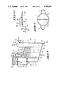
- FIG. 1 is a vertical section through an embodiment of the apparatus according to the invention.
- FIG. 2 is a view in cross-section taken upon the line II--II of FIG. 1;
- FIG. 3 is a view in vertical section showing another embodiment of the apparatus according to the invention.
- FIG. 4 is a view in cross-section taken upon the line IV--IV of FIG. 3;
- FIG. 5 is a view in vertical section of another embodiment of the apparatus according to the invention, with parts broken away;
- FIG. 6 is a view in cross-section taken upon the line VI--VI of FIG. 5;
- FIGS. 7 and 8 are conspectus or block diagrams of the apparatus of the invention with all the biogas circuitry
- FIG. 9 is a conspectus or block diagram of another embodiment of the invention apparatus and biogas circuitry
- FIGS. 10a, 10b, 11a, 11b are schematic views of the fermentation vessel of the invention apparatus to show the results of the method according to the invention on the state of the substrate within the fermentation vessel;
- FIG. 12 is a schematic view showing an apparatus for treating the fermented substrate at the output of the fermentation vessel.
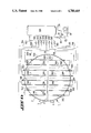
- FIG. 13 shows a modification of the invention apparatus subject matter of FIGS. 5 and 6 and is a view in cross-section of the bottom of the fermentation vessel, seen from the top thereof and shows all the biogas circuitry for introduction of biogas in the bottom of the fermentation vessel.
- FIGS. 1 and 2 a first embodiment of the invention apparatus or plant and in particular a first embodiment of the fermentation vessel or reactor thereof will be described.
- the fermentation portion or reactor 1 of the invention apparatus comprises a substrate feeding or supply means 3 here constituted by a substantially vertical shaft, closable in fully sealing or fluid-tight relationship by a cover or lid 3a, a fermentation vessel 2 with a dome-shaped cover 2a and a substrate discharging means 4, here constituted by a substantially vertical shaft, closable by a cover or lid 4a.
- the fermentation vessel 2 is separated by a partition wall 7 into a first part and a second part.
- the first part is connected to feeding means 3 and the second part is connected to discharge means 4.
- the partition wall 7 is here shown positioned substantially along a diameter of the vessel 2 and having a height smaller than that of the vessel 2.
- this partition wall 7 preferably leaves a passageway 7a at its lower portion, i.e. in the vicinity of the bottom of the vessel 2.
- the feed and discharge shafts 3 and 4 are arranged in diametrically opposite relationship on the periphery of the vessel 2 and are connected to the first and second parts, respectively, of the vessel 2 through syphons 5, 6.
- the syphon 5 may possibly be fitted with a means such as chains 35 flexible in one direction only and breaking or preventing any backflow or return of the substrate during the anaerobic fermentation towards the feed shaft 3.
- the vessel 2 comprises a gas outlet duct or pipeline 10 fitted with a shut-off valve 10a and opening in the shown embodiment into a hydraulic valve 11, the gas or biogas then evolving through the duct or pipeline 12 to flow to a gasometer 15 not shown on FIG. 1.
- the feed shaft also comprises two series of slots or slits 8 spaced from each other on the feed shaft 3 and circumferentially located thereon.
- the vessel 2 can also comprise chains 9 suspended from the dome-like portion 2a of the vessel 2, the function of which will be described later.
- the discharge shaft 4 is provided at its top with a cover 4a fitted with a gas duct or pipeline 115, an outlet syphon 127 and an outfall or like overflow chute or spillway 128 with an adjustable opening or outlet port 129.
- the apparatus 1 comprises several ducts either for draining away the gases from the discharge or feed shaft or for feeding air into this discharge or feed shaft or for feeding leaven or inoculum into the vessel 2. These various ducts will be described more in detail together with the description of the ducts of the apparatus.
- the second embodiment of the apparatus 1 according to the invention shown on FIGS. 3 and 4 differs from the first embodiment in that the hydraulic valve 11' is arranged within the reactor vessel 2, the latter being topped by a gasometer 15'.
- the valve 11' is fitted on a duct 10' one end of which extends as the pipe 10 on FIG. 1 from the top 2a of the vessel whereas its other end opens into the gasometer 15'.
- a pipe 145 which leads on the one hand to a condensing syphon 146 adapted to collect or recover the water present within the hot gases or biogases evolving from the fermentation and which is condensing within the pipe 145 and on the other hand to a duct for conveying the biogas produced for instance into a purifier, cleaner, scrubber or like filter means, a shut-off valve 147 being provided on the duct 145.
- a condensing syphon 146 adapted to collect or recover the water present within the hot gases or biogases evolving from the fermentation and which is condensing within the pipe 145 and on the other hand to a duct for conveying the biogas produced for instance into a purifier, cleaner, scrubber or like filter means, a shut-off valve 147 being provided on the duct 145.
- the fermentation vessel bottom 2b has one single slope or pitch and the inlet syphon 5 is located at a higher level than that of the syphon 6.
- the embodiment of the invention apparatus shown on FIGS. 5 and 6 differs from both previous embodiments in that the shafts 3 and 4 are arranged near each other on the periphery of the vessel 2.
- the partition wall 7 is then located between the inlets of both syphons 5, 6 within the fermentation vessel 2, its width being smaller than the width of the vessel so that the substrate may flow in the direction of the arrow F.
- the height of the partition wall 7 is smaller than that of the vessel 2.
- the syphon 5 associated with the feed shaft 3 is also positioned at a higher level than that of the syphon 6 associated with the discharge shaft 4.
- the bottom 2b of the fermentation vessel 2 exhibits a double slope or pitch and is advantageously of elliptic shape.
- the chains 9 fastened to the dome-shaped top 2a of the vessel 2 advantageously carry weighty or heavy elements 9a such as metal discs, these discs being fastened to the chains 9 preferably at the lower portions thereof.
- the chains 9 are suspended from the dome-shaped top 2a of the vessel so as to hang freely down into the vessel for being embedded at least partially into the substrate to be processed as clearly shown on FIGS. 10a, 10b, 11a, 11b. It is of course possible to arrange these chains 9 together with the weighty or heavy elements 9a within the vessel shown on FIGS. 1 to 4.
- the outlet syphon 127, the outfall or like overflow-shoot or spillway 128 provided on the discharge shaft 4 may be substituted for by a drain or egress duct fitted with a shut-off valve (not shown).
- the fermentation vessel 2 is connected to the hydraulic valve 11 through a gas outlet duct 10 fitted advantageously with a shut-off valve 10a.
- the hydraulic valve 11 is in turn connected to the gas holding vessel or gasometer 15 through a duct or pipeline 12 in which are mounted for instance a gasometer 14 and a container 13 forming a buffer gasometer.
- a gate or valve actuated for instance pneumatically, electrically, hydraulically, electromechanically and so on can be substituted for the hydraulic valve 11 for the same purpose.
- the gasometer 15 is fitted with an outlet duct 16 provided with a shut-off valve 16a and which is connected on the one hand to a duct 17 for carrying the gas for instance to a purifier, a storage station or a burner, and, on the other hand, to the inlet of a gas compressor or booster 18 to provide for the circulation of the biogas within the whole apparatus or plant.
- the outlet 19 of this gas compressor or booster 18 is connected through a duct 21 and branch ducts 22 and 23 through valves 22a,23a to the top portions of the feed and discharge shafts 3,4, respectively with the purpose of providing the pneumatic thrust of the substrate as previously emphasized.
- the outlet 19 of the booster 18 is also connected through a duct 20 fitted with a valve 20a to the bottom portions of the feed and discharge shafts 3,4 through the ducts 24,25; and to the bottom portion of the vessel 2 through a plurality of ducts 26, with, in the latter case, the purpose of injecting biogas at the bottom of the fermentation vessel 2.
- a preferred embodiment of said ducts will be described with reference to FIG. 13.
- the top portion of the fermentation vessel 2 is connected to the inlet of the compressor 18 through a duct 27 fitted with a valve 27a.
- the top portion of the fermentation vessel 2 can be connected to the outlet of the compressor 18 through a derivation duct 23' to duct 23 fitted with an associated valve 23'a with the purpose of performing a pneumatic thrust within the fermentation vessel 2 through injection of biogas through valve 23'a at the top of the fermentation vessel 2 simultaneously to the cutting off of the pneumatic thrust within discharge shaft 4.
- the ducts 26 opening into the bottom of the fermentation vessel 2 and the ducts 24,25 are fitted with check or non-return valves (not shown) for preventing materials contained within the vessel from falling into said ducts.
- the ducts 26 may possibly be provided with valve means (not shown) adapted to emit short and successive jets under pressure.
- FIG. 9 The gas circuit shown on FIG. 9 described hereinbelow is given by way of illustrative example only. It is of course possible to provide other ducts or devices, valves, gates or the like for carrying out any possible circuits for the flow of gas within the vessel and for instance to provide heat exchanges with other fluids within the apparatus or plant as shown on FIGS. 7 and 8.
- One fraction of the biogas recovered within the gasometer 15 is directly fed into the purifier 111 whereas another fraction is put in heat exchanging relationship with the air possibly supplied into the feed shaft 3, within the heat exchanger 110 and then through the ducts 108,113 and valves 109,112, it also undergoes a heat exchange within the heat exchanger 114 with the leaven re-cycled into the apparatus 1.
- This biogas fraction is then fed into the purifier 111 through the pipeline 115.
- the biogas present at the upper portions of the feed and discharge shafts is fed into the purifier 111.
- the best mode of the invention apparatus comprises fermentation vessel 2 of the type shown in FIGS. 5 and 6 but modified as follows with respect to introduction of biogas into the fermentation vessel 2 and fed from the gasometer of the type for instance of a gasometer 15 of FIG. 9.
- Duct 16 receiving biogas at the outlet of gasometer 15 is shown at the right of FIG. 13.
- the compressor 18 is provided on this duct 16 as shown in FIG. 9 and the duct 19 connected with the outlet of the compressor 18 is subdivided into ducts 20 and 21 exactly as in the case of FIG. 9.
- duct 20 does not deliver the biogas immediately to the bottom of the fermentation vessel 2 but is connected to a biogas storage container 300 able to support a high pressure and in which biogas is gathered and stored until obtention of a predetermined high pressure which will be defined later.
- a duct 302 is connected to the outlet of said biogas storage reservoir 300, said duct 302 being sub-divided into a plurality of sub-ducts 304,306,308,310,312,314,316,318, each being provided with an individual gate or valve, respectively 320-322-324-326-328-330-332-334.
- the sub-ducts 304 to 318 are feeding biogas to a plurality of biogas injection ducts 340,342,344,346,348,350,352,354,356,358,360,362,364,366,368,370 which are located in the locaion of the bottom of fermentation vessel 2 and which are constituted by hollow tubes of appropriate section longitudinally provided with a plurality of injection openings such as 372.
- said plurality of biogas injection ducts 340 to 370 is fed with biogas individually or in groups, for instance two by two as shown on FIG. 13, via the independent valves 320 to 334 so as to sub-divide the fermentation vessel 2 in sections independently fed with biogas.
- the limits of the sections have been symbolically materialized on FIG. 13 by the presence of the dotted lines 374,376,378,380,382,384,386. In the embodiment shown on FIG. 13, it thus appears that eight sections have been defined.
- the biogas injection ducts are laterally spaced between them and located at least in the major portion of the fermentation vessel 2, preferably regularly as shown. Further, the specific construction of the biogas injection ducts 340 to 370 is a part of the invention.
- each valve 320 to 334 is foreseen designed or constructed so as to provide a pressure in relation to the density of the products in the associated section.
- each valve is controlled preferably according to the invention through a programmed control device (not shown), so as to inject intermittently biogas into each of the sections of the fermentation vessel 2 under pressure and during a period of time predetermined, set in relation to the density of the products in the associated section.
- pressure of injection in relation to the density of the products in a given section is intended to emphasize that the injection pressure is sufficient to yield a fluidization of the mass of the products or substrate to be fermented or in fermentation having the said density.
- injection pressure is actually commensurate or adapted to the actual density of the mass of products or substrate in the section where is injected biogas.
- the previously set forth method is performed, namely the obtention of a sub-dividing of the fermentation vessel 2, into a plurality of sections.
- the invention method comprises injecting intermittently biogas into each one of the sections under pressure and during a period of time predetermined, set in function of the density of the products within the associated section.
- biogas is injected into each section successively while being shifted in the time so as to obtain a so-called biogas injection rotation within the fermentation vessel 2 from a section to the other.
- This injection can be regular or irregular and therefore a given section can be injected with biogas whereas one or several of the adjacent sections are not injected with biogas should in said sections the fluidization of the products be satisfactory, i.e. the density of the products.
- the programmed control device it can be obtained a programmed injection.
- This programmation can be automatically servo-controlled by means detecting a lack of fluidity within one of the sections of the fermentation vessel 2 so as to immediately order an injection in the concerned section by acting on the corresponding valve.
- biogas storage revervoir 300 provides unexpectedly for one skilled in the art the use of a compressor 18 of low capacity, namely with a low compression ratio.
- duct 23', FIG. 9, for injection of biogas at the top of the fermentation vessel 2 it can be performed a pneumatic thrust from the top of the fermentation vessel 2 so as to easier discharge the solid products flowing on the bottom of the fermentation vessel 2 towards the discharge shaft 4.
- the pneumatic thrust in the fermentation vessel 2 is performed simultaneously with the pneumatic thrust in the discharge shaft 4.
- the previously said pneumatic thrust in the substrate feeding shaft 4 is performed simultaneously to the setting to opening of biogas evacuating valve such as valve 10a of FIGS. 1 to 9, thereby improving the forced feeding of the products or substrate to be fermented.
- Organic products, by-products or waste from human, animal or vegetable origin are possibly subjected to a mechanical, physical, chemical or microbiological preliminary treatment, for instance to a heat processing, a pounding, crushing or milling or a chopping through a chopper-projector, a quick depressurization or pressure drop, an anaerobic pre-fermentation to for instance promote the hydrolysis of the matter, the defiberization, shredding or delignification in particular in the case of cellulosic and ligno-cellulosic compounds.
- a mechanical, physical, chemical or microbiological preliminary treatment for instance to a heat processing, a pounding, crushing or milling or a chopping through a chopper-projector, a quick depressurization or pressure drop, an anaerobic pre-fermentation to for instance promote the hydrolysis of the matter, the defiberization, shredding or delignification in particular in the case of cellulosic and ligno-cellul
- a gas is supplied into the top portion of the feed shaft 3 to build up a gas pressure, for instance through injection of compressed air produced by the compressor 28 and conveyed through the pipeline 29 to the lower portion of the feed shaft 3 or by feeding biogas through the pipeline 23 upon opening the shut-off valve 23a.
- the gas pressure prevailing at the bottom portion of the feed shaft 3 would drive or push the products or substrates through the syphon 5 for feeding same into the first portion of the fermentation vessel 2.
- the injection of air into the feed shaft 3 is carried out if it is desirable to oxygenate the substrate supplied or to induce, proceed with or continue a thermogenous aerobic fermentation of the substrate in accordance with the nature of the substrate to be treated.
- the substrate is thus fed into the first portion of the fermentation vessel 2 and through an upward motion would be poured into the second portion of the fermentation vessel 2 through overflow over the partition wall 7 and then after a downward motion would pass through the syphon 6 to rise within the discharge shaft 4 where one part will be periodically discharged by the syphon or spout 127 through opening of the cover 4a. It is also advantageous to inject the air into the discharge shaft 4 through the pipeline 36 for accelerating the process of conversion of the fermented substrate with a view of using same as a compost.
- the substrate recovered at the outlet of the discharge shaft 4 is fed through a spill-way or overflow shott 130 into a press 138 which would separate the fermented solid part from the liquid or leaven and which may possibly be subjected to an injection of air.
- a conveyor belt 139 removes the solid matter whereas the liquid is recovered or collected in a vat 30.
- This leaven or inoculum thus recovered may be used in various manners and may be re-cycled under the action of a pump 31 to the various portions of the reactor 1 after having possibly been reheated in the heat exchanger 114. It may thus be:
- valves 32a, 33a and 34a are advantageously provided with valves 32a, 33a and 34a, respectively.
- the nature of the substrate processed within such a plant may be very variable.
- the plant and the process according to the invention make it possible to conduct an anaerobic fermentation of organic products and in particular a methanogenesis with a substrate having a small content of dry matters or with a substrate having a high content of dry matter, of about 30% for instance or more and whether very heterogeneous or not.
- a first layer A loaded with gas and a lower liquid layer B will be obtained very quickly, heavy materials C having been separated or allowed to settle onto the bottom of the reactor.
- Within the layer A will then be built up a crust or cover which would obstruct or clog the reactor thereby preventing any circulation of the substrate and thus blocking or discontinuing the continuous operation of the digestor and causing the fermentation to stop.
- a homogenization and a fluidization of the substrate are carried out by using the biogas produced.
- Such a homogenization and fluidization are in the embodiment of the invention carried out through the combination of several effects connected with the re-cycling of the biogas within the substrate, with the flux and reflux motion of the substrate between the fermentation tank and the feed shaft 3 and/or discharge shaft 4 and at last with the movements of the chains 9 and discs 9a which latter can be absent.
- FIG. 10b has been diagrammatically illustrated the state of the substrate when a recirculation or bubbling of the biogas within said substrate is merely performed.
- This injection of biogas into the substrate is carried out by means of a compressor 18 either through the ducts 22, 23 or through the ducts 24, 25 or through the ducts 26 or through one or several of these ducts by the opening or closing of the valves 20a, 22a, 23a, 24a, 25a.
- FIGS. 11a, 11b has been shown the condition of the substrate in the case where the three combined effects of gas recirculation, the flux and reflux motions of the substrate and the movements of the chains 9 are applied.
- the flux and reflux or back and forth motion of the body of substrate between the vessel 2 and the feed and discharge shafts 3, 4 is achieved by means of the hydraulic valve 11 through which the pressure of the biogas contained above the substrate within the fermentation vessel 2 may be raised. During that time period the substrate is driven or forced into the discharge shaft 4 and/or the feed shaft 3 (FIG. 11a). When the pressure threshold is reached the hydraulic valve 11 enables the biogas to evolve towards the buffer gasometer 13 and the pressure prevailing within the fermentation vessel 2 suddenly drops and causes the substrate to flow back into said fermentation tank to reach its initial level again (FIG. 11b).
- the back and forth or flux and reflux motions of the substrate would induce the movements of the chains 9 kept stiff by the weighty or heavy elements 9a, thereby breaking the top surface or cover crust of the substrate which would build up during the methanization.
- the moistening or damping of this broken cover crust is effected forthwith thereby avoiding the formation of a crust through dehydration which may clog, choke or obstruct the reactor with time.
- the chains 9 and discs 9a form preferential paths of travel for the evolution of the biogas within the substrate.
- the method and the plant according to the invention will thus make it possible to treat under conditions very favourable for achieving a good anaerobic degradation a substrate with a small content of dry matters as well as a substrate with a high content of dry matters. It is thus possible on the one hand to substantially decrease the bulk or capacity of the fermentation tanks and on the other hand to provide for better conditions of development of the various steps of the process of anaerobic digestion.
- a substrate heavily loaded with dry matters indeed is a very good physical support for the microbiological populations required for the anaerobic digestion and its buffer capacity is improved during the fermentation.
- due to the high concentration of organic materials within the reactor the gas production is improved and owing to a better fixation of the biomass, the methods of digestion are made reliable and effective.
- the pneumatic drive or forcing of the products within the fermentation vessel 2 through a syphon and their discharge also through a syphon make it possible to periodically feed the substrate to be treated into the feed shaft 3 and to periodically remove or extract the fermented substrate from the discharge shaft 4 while always keeping a body of substrate within the fermentation vessel 2 so as to avoid blocking the continuous operation of the digestor thereby causing the fermentation to stop.
- the reactor 1 is advantageously fitted with a heating system which will keep the tank at the desired temperature to promote the anaerobic degradation process and such a heating system may for instance be integrated into the double bottom of the tank shown on FIG. 5.
- a heating system may for instance be integrated into the double bottom of the tank shown on FIG. 5.
- the reactor 1 and the various pipelines are fully insulated thermally for limiting the energy losses.
- various heat exchangers are provided between the fluids within the plants as shown on FIGS. 7 and 8 or for instance the leaven or inoculum is re-heated through passing same into a digestor located upstream of the reactor 1 wherein is carried out a preliminary treatment of the substrate through thermogenous aerobic degradation in order to thus optimize the power efficiency of the plant.
- the apparatus comprises, in a known manner, devices for measuring necessary physico-chemical values such as gas flow, temperature, pH, rH and the oxygen concentration.
Abstract
Description
Claims (20)
Applications Claiming Priority (6)
| Application Number | Priority Date | Filing Date | Title |
|---|---|---|---|
| FR8114740 | 1981-07-29 | ||
| FR8114740A FR2510605B1 (en) | 1981-07-29 | 1981-07-29 | METHOD AND APPARATUS FOR THE PRODUCTION OF A METHANOGENESIS |
| FR8212829 | 1982-07-22 | ||
| FR8212829A FR2530659B1 (en) | 1982-07-22 | 1982-07-22 | PROCESS AND INSTALLATION FOR REALIZING DEGRADATION IN ANAEROBIC MEDIA OF ORGANIC PRODUCTS, BY-PRODUCTS AND WASTE |
| CA435894 | 1983-09-01 | ||
| CA000435894A CA1225173A (en) | 1983-09-01 | 1983-09-01 | Method and apparatus for degrading of organic products, by-products and scraps in an anaerobic medium |
Related Parent Applications (1)
| Application Number | Title | Priority Date | Filing Date |
|---|---|---|---|
| US06402367 Continuation-In-Part | 1982-07-27 |
Publications (1)
| Publication Number | Publication Date |
|---|---|
| US4780415A true US4780415A (en) | 1988-10-25 |
Family
ID=27167378
Family Applications (1)
| Application Number | Title | Priority Date | Filing Date |
|---|---|---|---|
| US06/590,958 Expired - Lifetime US4780415A (en) | 1981-07-29 | 1984-03-19 | Method of degrading organic products, by-products and scraps in an anaerobic medium |
Country Status (1)
| Country | Link |
|---|---|
| US (1) | US4780415A (en) |
Cited By (28)
| Publication number | Priority date | Publication date | Assignee | Title |
|---|---|---|---|---|
| US4824571A (en) * | 1985-03-05 | 1989-04-25 | Union Industrielle Et D'entreprise | Method of and equipment for anaerobic degradation of organic products |
| US5427947A (en) * | 1993-03-25 | 1995-06-27 | Dalos; David E. | Environmental chamber and method for composting solid waste |
| US5470745A (en) * | 1992-02-12 | 1995-11-28 | Valorga Process | Apparatus for controlling the methane fermentation of organic materials |
| US5560819A (en) * | 1990-04-19 | 1996-10-01 | Mori-Gumi Co., Ltd. | Treating system for organic wastes and waste water |
| US5591635A (en) * | 1994-10-14 | 1997-01-07 | Dbs Manufacturing, Inc. | Methods and apparatuses for rapid composting with closed air loop circulation for positive control |
| US5651890A (en) * | 1995-04-04 | 1997-07-29 | Trost; Paul B. | Use of propane as stripper gas in anaerobic digestion of wastewaters |
| GB2333771A (en) * | 1998-01-28 | 1999-08-04 | William Richard Butterworth | Treating bio-degradable waste material |
| US6361694B1 (en) | 2000-06-26 | 2002-03-26 | Paul B. Trost | Enhanced biomass digestion through intermittent injection of propane |
| US6464875B1 (en) | 1999-04-23 | 2002-10-15 | Gold Kist, Inc. | Food, animal, vegetable and food preparation byproduct treatment apparatus and process |
| US6660518B1 (en) | 1999-07-30 | 2003-12-09 | Bioelex Corporation | Two-phase type methane fermentation reactor |
| US20040011734A1 (en) * | 2002-07-18 | 2004-01-22 | Cha Myung Chul | Lagoon for hog waste and the method of treatment thereof |
| US20040108267A1 (en) * | 2001-03-26 | 2004-06-10 | Vellinga Sjoerd Hubertus Jozef | Method and device for the anaerobic purification of a slurry which contains organic constituents |
| US20060289356A1 (en) * | 2005-05-13 | 2006-12-28 | Burnett Clyde H | Digesters |
| US20070062866A1 (en) * | 2005-09-19 | 2007-03-22 | Keith Wilson | Two-stage anaerobic digester |
| US20070114173A1 (en) * | 1999-10-25 | 2007-05-24 | Ghd, Inc. | Method and apparatus for solids processing |
| WO2008066508A1 (en) * | 2006-11-27 | 2008-06-05 | Ghd, Inc. | Anaerobic digester employing circular tank |
| DE102008046879A1 (en) * | 2008-09-11 | 2010-03-25 | Schmack Biogas Ag | Process for biogas upgrading and biogas plant |
| US20100140169A1 (en) * | 2006-11-27 | 2010-06-10 | Dvorak Stephen W | Method and Apparatus for Anaerobic Digestion of Organic Liquid Waste Streams |
| US20100314310A1 (en) * | 2007-11-28 | 2010-12-16 | Bio Group Limited | Anaerobic digestion process and apparatus |
| CN102286361A (en) * | 2011-07-13 | 2011-12-21 | 南开大学 | Biomass fermentation reaction device and application |
| US20120009668A1 (en) * | 2007-10-02 | 2012-01-12 | Clearford Industries Inc. | Biogas Capture and/or Collection System |
| WO2014021599A1 (en) * | 2012-07-31 | 2014-02-06 | Jang Hee Hyun | Digester apparatus |
| DE102012024552A1 (en) * | 2012-12-17 | 2014-06-18 | Prüf- und Forschungsinstitut Pirmasens e.V. | Energy-optimized storage and fermentation container for power generation and energy storage systems and methods for optimizing the use of heat in such a container |
| US8835155B2 (en) | 2009-11-25 | 2014-09-16 | Dvo Licensing, Inc. | Biosolids digester and process for biosolids production |
| WO2016090046A1 (en) * | 2014-12-02 | 2016-06-09 | Selifonov Sergey Alexandrovich | Process and apparatus for treatment of biomass |
| FR3045594A1 (en) * | 2015-12-21 | 2017-06-23 | Jean-Luc Sallustro | INSTALLATION AND METHOD FOR BIOLOGICAL TREATMENT OF WASTE AND ORGANIC EFFLUENTS |
| EP3634917A4 (en) * | 2017-06-05 | 2021-05-12 | Cambrian Innovation, Inc. | Process for a fixed film reactor and apparatus related thereto |
| US11267736B2 (en) * | 2017-12-11 | 2022-03-08 | Veolia Water Solutions & Technologies Support | Simultaneous phase operated anaerobic sequential batch reactor |
Citations (10)
| Publication number | Priority date | Publication date | Assignee | Title |
|---|---|---|---|---|
| US3630848A (en) * | 1967-12-29 | 1971-12-28 | Louis Alfred Auguste Lefrancoi | Continuous fermentation method and device |
| FR2305113A1 (en) * | 1975-03-24 | 1976-10-22 | Ducellier Gilbert | Anaerobic fermentation digester for organic matter - comprises insulated enclosure with two compartments |
| US4001090A (en) * | 1974-05-28 | 1977-01-04 | Societe D'assistance Technique Pour Produits Nestle S.A. | Process and apparatus for the culture of microorganisms |
| US4057401A (en) * | 1976-09-03 | 1977-11-08 | Bio-Gas Corporation | Methane gas process and apparatus |
| US4082672A (en) * | 1976-08-16 | 1978-04-04 | Liquid Removal Service Co., Inc. | Mobile sludge trailer and method of filling and emptying same |
| US4111808A (en) * | 1975-12-11 | 1978-09-05 | Fair John H | Apparatus for sludge digestion |
| US4334998A (en) * | 1979-06-29 | 1982-06-15 | Agence Nationale De Valorisation De La Recherche (Anvar) | Process for placing a gas phase, at least one liquid phase, and at least one comminuted solid phase in contact |
| US4482458A (en) * | 1982-09-28 | 1984-11-13 | Degremont | Process and apparatus for the anaerobic treatment of waste water in a filter including granular material |
| US4514297A (en) * | 1982-12-09 | 1985-04-30 | A. Ahlstrom Osakeyhtio | Bioreactor |
| US4579654A (en) * | 1982-06-25 | 1986-04-01 | Corite Investments Ltd. | Apparatus for the anaerobic fermentation of organic waste material such as liquid manure |
-
1984
- 1984-03-19 US US06/590,958 patent/US4780415A/en not_active Expired - Lifetime
Patent Citations (10)
| Publication number | Priority date | Publication date | Assignee | Title |
|---|---|---|---|---|
| US3630848A (en) * | 1967-12-29 | 1971-12-28 | Louis Alfred Auguste Lefrancoi | Continuous fermentation method and device |
| US4001090A (en) * | 1974-05-28 | 1977-01-04 | Societe D'assistance Technique Pour Produits Nestle S.A. | Process and apparatus for the culture of microorganisms |
| FR2305113A1 (en) * | 1975-03-24 | 1976-10-22 | Ducellier Gilbert | Anaerobic fermentation digester for organic matter - comprises insulated enclosure with two compartments |
| US4111808A (en) * | 1975-12-11 | 1978-09-05 | Fair John H | Apparatus for sludge digestion |
| US4082672A (en) * | 1976-08-16 | 1978-04-04 | Liquid Removal Service Co., Inc. | Mobile sludge trailer and method of filling and emptying same |
| US4057401A (en) * | 1976-09-03 | 1977-11-08 | Bio-Gas Corporation | Methane gas process and apparatus |
| US4334998A (en) * | 1979-06-29 | 1982-06-15 | Agence Nationale De Valorisation De La Recherche (Anvar) | Process for placing a gas phase, at least one liquid phase, and at least one comminuted solid phase in contact |
| US4579654A (en) * | 1982-06-25 | 1986-04-01 | Corite Investments Ltd. | Apparatus for the anaerobic fermentation of organic waste material such as liquid manure |
| US4482458A (en) * | 1982-09-28 | 1984-11-13 | Degremont | Process and apparatus for the anaerobic treatment of waste water in a filter including granular material |
| US4514297A (en) * | 1982-12-09 | 1985-04-30 | A. Ahlstrom Osakeyhtio | Bioreactor |
Cited By (45)
| Publication number | Priority date | Publication date | Assignee | Title |
|---|---|---|---|---|
| US4824571A (en) * | 1985-03-05 | 1989-04-25 | Union Industrielle Et D'entreprise | Method of and equipment for anaerobic degradation of organic products |
| US5560819A (en) * | 1990-04-19 | 1996-10-01 | Mori-Gumi Co., Ltd. | Treating system for organic wastes and waste water |
| US5470745A (en) * | 1992-02-12 | 1995-11-28 | Valorga Process | Apparatus for controlling the methane fermentation of organic materials |
| US5427947A (en) * | 1993-03-25 | 1995-06-27 | Dalos; David E. | Environmental chamber and method for composting solid waste |
| US5584904A (en) * | 1993-03-25 | 1996-12-17 | Dalos; David E. | Method for composting solid waste |
| US5591635A (en) * | 1994-10-14 | 1997-01-07 | Dbs Manufacturing, Inc. | Methods and apparatuses for rapid composting with closed air loop circulation for positive control |
| US5651890A (en) * | 1995-04-04 | 1997-07-29 | Trost; Paul B. | Use of propane as stripper gas in anaerobic digestion of wastewaters |
| GB2333771A (en) * | 1998-01-28 | 1999-08-04 | William Richard Butterworth | Treating bio-degradable waste material |
| US6464875B1 (en) | 1999-04-23 | 2002-10-15 | Gold Kist, Inc. | Food, animal, vegetable and food preparation byproduct treatment apparatus and process |
| US6660518B1 (en) | 1999-07-30 | 2003-12-09 | Bioelex Corporation | Two-phase type methane fermentation reactor |
| US20070114173A1 (en) * | 1999-10-25 | 2007-05-24 | Ghd, Inc. | Method and apparatus for solids processing |
| US8202721B2 (en) | 1999-10-25 | 2012-06-19 | Dvo, Inc. | Method and apparatus for solids processing |
| US6361694B1 (en) | 2000-06-26 | 2002-03-26 | Paul B. Trost | Enhanced biomass digestion through intermittent injection of propane |
| US20040108267A1 (en) * | 2001-03-26 | 2004-06-10 | Vellinga Sjoerd Hubertus Jozef | Method and device for the anaerobic purification of a slurry which contains organic constituents |
| US6841072B2 (en) * | 2001-03-26 | 2005-01-11 | Paques Bio Systems B.V. | Method and device for the anaerobic purification of a slurry which contains organic constituents |
| US20040011734A1 (en) * | 2002-07-18 | 2004-01-22 | Cha Myung Chul | Lagoon for hog waste and the method of treatment thereof |
| US6764600B2 (en) * | 2002-07-18 | 2004-07-20 | Environmental Vision 21, Ltd. | Lagoon for hog waste and the method of treatment thereof |
| US20060289356A1 (en) * | 2005-05-13 | 2006-12-28 | Burnett Clyde H | Digesters |
| US20070062866A1 (en) * | 2005-09-19 | 2007-03-22 | Keith Wilson | Two-stage anaerobic digester |
| US7560026B2 (en) * | 2005-09-19 | 2009-07-14 | Keith Wilson | Two-stage anaerobic digester |
| US20100173391A1 (en) * | 2006-11-27 | 2010-07-08 | Dvorak Stephen W | Anaerobic Digester Employing Circular Tank |
| US8394271B2 (en) | 2006-11-27 | 2013-03-12 | Dvo, Inc. | Anaerobic digester employing circular tank |
| US20100140169A1 (en) * | 2006-11-27 | 2010-06-10 | Dvorak Stephen W | Method and Apparatus for Anaerobic Digestion of Organic Liquid Waste Streams |
| US8470177B2 (en) | 2006-11-27 | 2013-06-25 | Dvo Licensing, Inc. | Method and apparatus for anaerobic digestion of organic liquid waste streams |
| WO2008066508A1 (en) * | 2006-11-27 | 2008-06-05 | Ghd, Inc. | Anaerobic digester employing circular tank |
| CN101600660B (en) * | 2006-11-27 | 2012-07-04 | Dvo公司 | Anaerobic digester employing circular tank |
| US20120009668A1 (en) * | 2007-10-02 | 2012-01-12 | Clearford Industries Inc. | Biogas Capture and/or Collection System |
| US20100314310A1 (en) * | 2007-11-28 | 2010-12-16 | Bio Group Limited | Anaerobic digestion process and apparatus |
| US8759601B2 (en) | 2008-09-11 | 2014-06-24 | Schmack Biogas Ag | Method for biogas treatment and biogas installation |
| DE102008046879A1 (en) * | 2008-09-11 | 2010-03-25 | Schmack Biogas Ag | Process for biogas upgrading and biogas plant |
| US8835155B2 (en) | 2009-11-25 | 2014-09-16 | Dvo Licensing, Inc. | Biosolids digester and process for biosolids production |
| US10717684B2 (en) | 2009-11-25 | 2020-07-21 | Dvo Licensing, Inc. | Biosolids digester and process for biosolids production |
| CN102286361A (en) * | 2011-07-13 | 2011-12-21 | 南开大学 | Biomass fermentation reaction device and application |
| WO2014021599A1 (en) * | 2012-07-31 | 2014-02-06 | Jang Hee Hyun | Digester apparatus |
| DE102012024552A1 (en) * | 2012-12-17 | 2014-06-18 | Prüf- und Forschungsinstitut Pirmasens e.V. | Energy-optimized storage and fermentation container for power generation and energy storage systems and methods for optimizing the use of heat in such a container |
| EP2743340A1 (en) | 2012-12-17 | 2014-06-18 | Prüf- und Forschungsinstitut Pirmasens E. V. | Energy optimised storage and fermentation vessel for energy generation and energy storage installations and method for optimising the utilisation of heat in such a container |
| US10337075B2 (en) | 2014-12-02 | 2019-07-02 | Sergey Alexandrovich Selifonov | Process and apparatus for treatment of biomass |
| WO2016090046A1 (en) * | 2014-12-02 | 2016-06-09 | Selifonov Sergey Alexandrovich | Process and apparatus for treatment of biomass |
| WO2017109398A1 (en) * | 2015-12-21 | 2017-06-29 | Jua Group | Facility and method for biologically treating organic waste and effluents |
| CN108698871A (en) * | 2015-12-21 | 2018-10-23 | 朱亚集团 | Device and method for biological treatment debirs and sewage |
| FR3045594A1 (en) * | 2015-12-21 | 2017-06-23 | Jean-Luc Sallustro | INSTALLATION AND METHOD FOR BIOLOGICAL TREATMENT OF WASTE AND ORGANIC EFFLUENTS |
| US11142474B2 (en) | 2015-12-21 | 2021-10-12 | Jua Group | Facility and method for biologically treating organic waste and effluents |
| CN108698871B (en) * | 2015-12-21 | 2022-01-28 | 朱亚集团 | Apparatus and method for biological treatment of organic waste and sewage |
| EP3634917A4 (en) * | 2017-06-05 | 2021-05-12 | Cambrian Innovation, Inc. | Process for a fixed film reactor and apparatus related thereto |
| US11267736B2 (en) * | 2017-12-11 | 2022-03-08 | Veolia Water Solutions & Technologies Support | Simultaneous phase operated anaerobic sequential batch reactor |
Similar Documents
| Publication | Publication Date | Title |
|---|---|---|
| US4780415A (en) | Method of degrading organic products, by-products and scraps in an anaerobic medium | |
| EP0918876B1 (en) | Method and apparatus for producing organic acids | |
| US5782950A (en) | Device and process for composting and wet fermentation of biological waste | |
| US4435188A (en) | Installation for preparing combustible gases through fermentation | |
| US8262853B2 (en) | Methods for pretreatment and processing of biomass | |
| CN101381674B (en) | Vertical non-stirred organic waste dry-type anaerobic digestion processing equipment and method | |
| CN101200693B (en) | Method and device for the anaerobic fermentation of organic material | |
| JP2009532193A (en) | Devices, processes and systems for anaerobic digestion of sludge | |
| CN107473549A (en) | A kind of agricultural wastes cyclic utilization system | |
| CN105861306A (en) | Solid-liquid two-phase anaerobic fermentation apparatus and method | |
| CN208649156U (en) | A kind of Straw manures installation for fermenting | |
| CN106116734A (en) | The aerobic composting device of organic solid castoff and aerobic compost method | |
| US20080307705A1 (en) | Transport Device for Biomass in a Fermenter for the Generation of Biogas | |
| CN102492728A (en) | Rancidity-prone waste biogas utilization method based on in-subarea inoculation and quick start | |
| CN205576158U (en) | Two stage of solid -liquid anaerobic fermentation device | |
| JPH0438476B2 (en) | ||
| CN111534416A (en) | Fermentation equipment and fermentation method for organic matters | |
| GB2407088A (en) | Anaerobic waste treatment process and apparatus | |
| CA1225173A (en) | Method and apparatus for degrading of organic products, by-products and scraps in an anaerobic medium | |
| CN205774176U (en) | A kind of aerobic composting device of organic solid castoff | |
| CN212669681U (en) | Fermentation equipment of organic matter | |
| CN116157363A (en) | Method and apparatus for treating organic waste, including anaerobic digestion thereof and composting of digestate | |
| RU2399184C1 (en) | Biogas complex | |
| CN210103937U (en) | Organic matter anaerobic dry fermentation device | |
| WO2004041995A1 (en) | Methods and systems for pretreatment and processing of biomass |
Legal Events
| Date | Code | Title | Description |
|---|---|---|---|
| AS | Assignment |
Owner name: UNION INDUSTRIELLE ET D'ENTREPRISE AND VALORGA 32 Free format text: ASSIGNS TO EACH ASSIGNEE THE AMOUNT SPECIFIED BY THEIR RESPECTIVE NAMES;ASSIGNORS:DUCELLIER, GILBERT;PAVIA, ANDRE;REEL/FRAME:004362/0620;SIGNING DATES FROM Owner name: Z.I. LA LAUZE, LOT. 34430 SAINT JEAN DE VEDAS FRAN Free format text: ASSIGNS TO EACH ASSIGNEE THE AMOUNT SPECIFIED BY THEIR RESPECTIVE NAMES;ASSIGNORS:DUCELLIER, GILBERT;PAVIA, ANDRE;REEL/FRAME:004362/0620;SIGNING DATES FROM |
|
| STCF | Information on status: patent grant |
Free format text: PATENTED CASE |
|
| FEPP | Fee payment procedure |
Free format text: PAYOR NUMBER ASSIGNED (ORIGINAL EVENT CODE: ASPN); ENTITY STATUS OF PATENT OWNER: LARGE ENTITY |
|
| FPAY | Fee payment |
Year of fee payment: 4 |
|
| FEPP | Fee payment procedure |
Free format text: PAYER NUMBER DE-ASSIGNED (ORIGINAL EVENT CODE: RMPN); ENTITY STATUS OF PATENT OWNER: LARGE ENTITY Free format text: PAYOR NUMBER ASSIGNED (ORIGINAL EVENT CODE: ASPN); ENTITY STATUS OF PATENT OWNER: LARGE ENTITY |
|
| FPAY | Fee payment |
Year of fee payment: 8 |
|
| FPAY | Fee payment |
Year of fee payment: 12 |