US4789771A - Method and apparatus for substrate heating in an axially symmetric epitaxial deposition apparatus - Google Patents
Method and apparatus for substrate heating in an axially symmetric epitaxial deposition apparatus Download PDFInfo
- Publication number
- US4789771A US4789771A US07/031,519 US3151987A US4789771A US 4789771 A US4789771 A US 4789771A US 3151987 A US3151987 A US 3151987A US 4789771 A US4789771 A US 4789771A
- Authority
- US
- United States
- Prior art keywords
- chamber
- substrate
- heating
- lamps
- circular substrate
- Prior art date
- Legal status (The legal status is an assumption and is not a legal conclusion. Google has not performed a legal analysis and makes no representation as to the accuracy of the status listed.)
- Expired - Lifetime
Links
Images

Classifications
-
- C—CHEMISTRY; METALLURGY
- C30—CRYSTAL GROWTH
- C30B—SINGLE-CRYSTAL GROWTH; UNIDIRECTIONAL SOLIDIFICATION OF EUTECTIC MATERIAL OR UNIDIRECTIONAL DEMIXING OF EUTECTOID MATERIAL; REFINING BY ZONE-MELTING OF MATERIAL; PRODUCTION OF A HOMOGENEOUS POLYCRYSTALLINE MATERIAL WITH DEFINED STRUCTURE; SINGLE CRYSTALS OR HOMOGENEOUS POLYCRYSTALLINE MATERIAL WITH DEFINED STRUCTURE; AFTER-TREATMENT OF SINGLE CRYSTALS OR A HOMOGENEOUS POLYCRYSTALLINE MATERIAL WITH DEFINED STRUCTURE; APPARATUS THEREFOR
- C30B25/00—Single-crystal growth by chemical reaction of reactive gases, e.g. chemical vapour-deposition growth
- C30B25/02—Epitaxial-layer growth
- C30B25/10—Heating of the reaction chamber or the substrate
- C30B25/105—Heating of the reaction chamber or the substrate by irradiation or electric discharge
Definitions
- This invention relates generally to epitaxial deposition of materials on a substrate and, more particularly, to epitaxial deposition of materials on a substrate in an axially symmetric configuration. Because of the axially symmetric configuration, the deposition chamber must be specifically designed to provide for uniform heating of substrate.
- the quality of the deposited material in an epitaxial deposition chamber can depend, among other things, on the uniformity of the temperature of the substrate and the uniformity of deposition material in the carrier gas.
- the advantages of epitaxial deposition in an axially symmetric configuration have been identified.
- the full advantage of this configuration in a commercial environment can be realized only with rapid, uniform heating of the substrate.
- massive susceptors have been heated by arrays of linear lamps or by RF fields, with temperature uniformity provided in part by the large thermal mass and high thermal conductivity of a susceptor associated with the substrate.
- the high thermal mass of the susceptor provides a thermal inertia that prolongs the heating and cooling cycles associated with the epitaxial deposition process.
- an epitaxial reactor device generally comprised of an upper chamber and a lower chamber substantially enclosing a substrate-susceptor combination.
- a series of heat lamps extend through the interior of the chamber generating at least a portion of the thermal energy for the semiconductor substrate-susceptor combination.
- the heat lamps are generally parallel and can be equally spaced, and when a circular chamber is used, can have varying portions of the lamps extending through the circular chamber.
- the reflectivity of the chamber walls is chosen to complement the heat lamps and to provide a uniform distribution of heating radiation within the reactor.
- a circular lower chamber of the reactor is designed similarly to a circular upper portion.
- a lower chamber of the reactor comprises a circular chamber in which reflected energy from a circular upper chamber is used to provide thermal energy to the lower portion of the substrate-susceptor combination.
- a center portion of the lower chamber wall has a reflectivity chosen to provide uniform heating of the substrate-susceptor combination by having reflectivity different from that of the remainder of the chamber.
- heat lamps in upper and lower chambers have parabolic reflectors associated therewith for providing generally parallel radiation impinging on the substrate-susceptor combination.
- the chambers preferably have a square configuration.
- At least one of the chambers can have the parabolic reflectors replaced by a flat reflecting surface for selected heat lamps.
- the walls of the reflectors have deposited thereon a suitable reflecting medium.
- the heating lamps can have a higher excitation energy or a smaller inter-lamp spacing, as the distance from the center lamps is increased to compensate, for example, for heat losses through ports necessary, for example, to introduce gas components into the reactor.
- FIG. 1 is a schematic diagram showing the flow of gas toward a substrate to produce an axially symmetric flow.
- FIG. 2 is a perspective view of one chamber of the reactor having heating lamps passing therethrough.
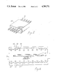
- FIG. 3 is a schematic cross-section diagram of a configuration for uniformly heating a substrate-susceptor combination utilizing heat lamps above and below the combination.
- FIG. 4 is a schematic cross-section diagram showing the configuration in which a substrate-susceptor combination is heated by a group of lamps above the combination and is heated by reflected energy from the other side of the combination.
- FIG. 5 is a perspective view of a different configuration of a heating chamber with a heating lamp extending therethrough.
- FIG. 6 is a schematic cross-section diagram showing the configuration in which a substrate susceptor combination is heated by a plurality of lamps with associated parabolic and planar reflectors.
- the technique consists of projecting a gas carrying the deposition materials with a uniform velocity perpendicular to the substrate 10 and susceptor 15 combination.
- the gas is conducted from the edge of the circular substrate-susceptor combination, and the result is a configuration for a chemical reaction generally referred to as the stagnation point flow configuration.
- stagnation point flow is meant a flow of gas toward a circular substrate that has a uniform temperature and a uniform component of velocity toward the substrate at a predetermined distance.
- FIG. 2 a perspective view of one chamber 49 of a reactor is shown with the heating lamps 50 passing therethrough.
- the heating chamber 49 is circular.
- the general structure of the reactor for heating the substrate 10 and the associated susceptor 15 is shown.
- the apparatus shown in this cross-section is not complete.
- the apparatus for generating the uniform flow of gas toward the substrate is missing as well as structures necessary to support the substrate.
- the essential portions of the apparatus relating to heating of the susceptor 15 and the substrate 10 are shown.
- the reactor is comprised of two circular chambers 49, one above and one below the substrate-susceptor combination.
- the purpose of the reactor configuration is to provide an environment that, to the extent possible, provides uniform radiation for the substrate and the associated susceptor. When the radiation is uniform, the temperature of the substrate-susceptor combination will be uniform to the extent that thermal losses are also uniform.
- the top portion has a circular surface area with a cylindrical side portion. Inserted through the cylinder portion of the chamber 49 are a series of parallel heat lamps 50.
- the surface of the upper chamber is coated with a diffuse reflecting material, such as a gold plating, and the sides of the chamber are coated with a diffuse or a specular reflecting material.
- the bottom chamber 49 in this embodiment, is similar to the upper chamber with the exception that the lamps 50 are positioned generally at right angles to the lamps in the upper chamber.
- the bottom and the side surfaces of the chamber 60 have coatings similar to those described for the upper chamber. Openings 71 between the two chambers, used for introducing gas into the cavity as well as other functions, is important because this region is thermally cool, and tends to produce non-uniform heat losses from the circumference of the substrate.
- the upper chamber 49 of this embodiment has a similar configuration to the upper chamber shown in the embodiment in FIG. 2.
- the lamps 50 of the upper chamber are present, the diffuse reflecting material 52 is coated on the upper surface, and the side surfaces can have either a diffuse or a specular reflecting coating 53.
- a second chamber 61 below the upper chamber is a second chamber 61.
- Chamber 61 has a surface 54 that is coated on the side and a portion of the bottom floor with a diffuse reflector material having, for example, reflectivity of the order of 0.95.
- a circular area 55 has a diffuse reflective coating with a reflectivity lower than that of the other portions, the reflectivity being of the order of 0.8 in the specific configuration described.
- the lower chamber 61 is used to heat the substrate-susceptor combination using radiation from the upper chamber. Again, aperture 71 is present resulting in a non-uniform radiation field.
- FIG. 5 a different configuration for for the heating chambers is shown.
- the chamber 49 is generally square in nature. Again, heating lamps 50 are inserted therethrough to provide for radiant heating of the substrate-susceptor combination.
- This configuration has the disadvantage that the symmetry of the substrate-susceptor combination is not present in the chamber configuration. Despite the lack of axial symmetry, it is found that this configuration can result in a uniform substrate-susceptor combination heating.
- the heating lamps 50 have the emitted radiation reflected by parabolic reflectors 53.
- the parabolic reflectors can be approximated by other geometric surface configurations.
- the parabolic reflector causes the reflected radiation to be parallel thereby increasing the uniformity of the radiation impinging on selected areas the substrate-susceptor combination.
- the heating lamps in the lower chamber are generally disposed at right angles to the heating lamps of the upper chamber to average some of the structure imposed on the radiation impinging on the substrate-susceptor combination because of the use of discrete heat sources.
- Thermal aperture 71 is present as in previous configurations and compromises the uniformity of the radiation field.
- the parabolic reflectors can be replaced by a plane for interior heat lamps of the chamber.
- the exterior parabolic reflector of the group of reflectors can be implemented so that the reflectors can be tilted, thereby providing additional control for environment of the substrate-susceptor combination.
- the function of the chambers of the epitaxial reactor is to provide, from the perspective of the substrate and associated susceptor, a cavity having uniform radiation field for heating the substrate-susceptor combination. Because of the necessity for introducing and removing the gas with the deposition materials, as well as the necessity for introducing and removing the substrate-susceptor combination itself, the reactor cannot have a truly uniform source of radiation because of requisite apertures for accomplishing the associated functions.
- the aperture 71 can therefore be critical in any effort to provide a uniform temperature environment for the substrate/susceptor combination because the thermal losses through the aperture cool the combination non-uniformity. However, the regions that do not contain a source of radiation can be made relatively small.
- the end lamps of the array 50 can be operated at elevated power levels producing a higher temperature, and therefore higher radiation intensity, than the other heating lamps. This additional heating can compensate for the otherwise lower radiation intensity at the circumference of the substrate.
- the heat lamps in the bottom chamber are placed at a large angle, approximately 90°, with respect to the lamps in the upper chamber.
- a diffuse reflector is deposited on the various portions of the chamber other than the parabolic reflectors to simulate as nearly as possible a constant temperature region as viewed from any region of the substrate.
- the substrate-susceptor combination can be rotated to further average any departures from the observance of a uniform temperature environment for the substrate-susceptor combination.
- the lower chamber does not produce power directly, but reflects power from the upper heating chamber. It has been found by computer simulation that, in order to achieve a uniform temperature in this configuration, it is necessary to have a region 55 with an intermediate magnitude reflectivity. Region 55 causes the center of the substrate-susceptor combination to receive a lower intensity of reflected radiation compared with the circumference, thus compensating for the nonuniform radiation discussed previously.
- the areas 54 include a diffuse reflector with a reflectivity on the order of 0.95, while the area 55 includes a diffuse reflector with a reflectivity of about 0.8.
- the diameter of area 55 is approximately two-thirds the diameter of the susceptor-substrate combination. However, this relationship is a function of size of the substrate, distance between the substrate and the reflecting surface, and the other structural dimensions.
- the dimension of the chamber can be expanded so that the aperture 71 has a smaller influence on the non-uniform field experienced by the substrate/susceptor combination.
- the use of square heating chambers provides a situation where the corners of the heating chamber provide a larger effective chamber and can minimize the influence of aperture 71.
Abstract
Description
Claims (20)
Priority Applications (1)
| Application Number | Priority Date | Filing Date | Title |
|---|---|---|---|
| US07/031,519 US4789771A (en) | 1985-10-07 | 1987-03-27 | Method and apparatus for substrate heating in an axially symmetric epitaxial deposition apparatus |
Applications Claiming Priority (2)
| Application Number | Priority Date | Filing Date | Title |
|---|---|---|---|
| US06/784,739 US4654509A (en) | 1985-10-07 | 1985-10-07 | Method and apparatus for substrate heating in an axially symmetric epitaxial deposition apparatus |
| US07/031,519 US4789771A (en) | 1985-10-07 | 1987-03-27 | Method and apparatus for substrate heating in an axially symmetric epitaxial deposition apparatus |
Related Parent Applications (1)
| Application Number | Title | Priority Date | Filing Date |
|---|---|---|---|
| US06/784,739 Division US4654509A (en) | 1985-10-07 | 1985-10-07 | Method and apparatus for substrate heating in an axially symmetric epitaxial deposition apparatus |
Publications (1)
| Publication Number | Publication Date |
|---|---|
| US4789771A true US4789771A (en) | 1988-12-06 |
Family
ID=26707345
Family Applications (1)
| Application Number | Title | Priority Date | Filing Date |
|---|---|---|---|
| US07/031,519 Expired - Lifetime US4789771A (en) | 1985-10-07 | 1987-03-27 | Method and apparatus for substrate heating in an axially symmetric epitaxial deposition apparatus |
Country Status (1)
| Country | Link |
|---|---|
| US (1) | US4789771A (en) |
Cited By (62)
| Publication number | Priority date | Publication date | Assignee | Title |
|---|---|---|---|---|
| WO1990010093A1 (en) * | 1989-02-28 | 1990-09-07 | Moore Epitaxial, Inc. | A high capacity epitaxial reactor |
| US4993355A (en) * | 1987-03-31 | 1991-02-19 | Epsilon Technology, Inc. | Susceptor with temperature sensing device |
| WO1991010873A1 (en) * | 1990-01-19 | 1991-07-25 | G-Squared Semiconductor Corporation | Heating apparatus for semiconductor wafers or substrates |
| US5053247A (en) * | 1989-02-28 | 1991-10-01 | Moore Epitaxial, Inc. | Method for increasing the batch size of a barrel epitaxial reactor and reactor produced thereby |
| US5136978A (en) * | 1989-10-30 | 1992-08-11 | The United States Of America As Represented By The Secretary Of The Air Force | Heat pipe susceptor for epitaxy |
| US5155336A (en) * | 1990-01-19 | 1992-10-13 | Applied Materials, Inc. | Rapid thermal heating apparatus and method |
| US5156820A (en) * | 1989-05-15 | 1992-10-20 | Rapro Technology, Inc. | Reaction chamber with controlled radiant energy heating and distributed reactant flow |
| US5158906A (en) * | 1991-06-13 | 1992-10-27 | Huang Chi Tso | Method of producing dielectric isolated single crystalline thin film |
| US5179677A (en) * | 1990-08-16 | 1993-01-12 | Applied Materials, Inc. | Apparatus and method for substrate heating utilizing various infrared means to achieve uniform intensity |
| DE4202944A1 (en) * | 1992-02-01 | 1993-08-05 | Heraeus Quarzglas | METHOD AND DEVICE FOR HEATING A MATERIAL |
| US5239614A (en) * | 1990-11-14 | 1993-08-24 | Tokyo Electron Sagami Limited | Substrate heating method utilizing heating element control to achieve horizontal temperature gradient |
| US5318634A (en) * | 1987-03-31 | 1994-06-07 | Epsilon Technology, Inc. | Substrate supporting apparatus |
| US5370739A (en) * | 1992-06-15 | 1994-12-06 | Materials Research Corporation | Rotating susceptor semiconductor wafer processing cluster tool module useful for tungsten CVD |
| US5374315A (en) * | 1987-03-31 | 1994-12-20 | Advanced Semiconductor Materials America, Inc. | Rotatable substrate supporting mechanism with temperature sensing device for use in chemical vapor deposition equipment |
| US5434110A (en) * | 1992-06-15 | 1995-07-18 | Materials Research Corporation | Methods of chemical vapor deposition (CVD) of tungsten films on patterned wafer substrates |
| US5444217A (en) * | 1993-01-21 | 1995-08-22 | Moore Epitaxial Inc. | Rapid thermal processing apparatus for processing semiconductor wafers |
| US5580388A (en) * | 1993-01-21 | 1996-12-03 | Moore Epitaxial, Inc. | Multi-layer susceptor for rapid thermal process reactors |
| WO1997003225A1 (en) * | 1995-07-10 | 1997-01-30 | Cvc Products, Inc. | Programmable ultraclean electromagnetic substrate rotation apparatus and method for microelectronics manufacturing equipment |
| US5820686A (en) * | 1993-01-21 | 1998-10-13 | Moore Epitaxial, Inc. | Multi-layer susceptor for rapid thermal process reactors |
| US5930456A (en) * | 1998-05-14 | 1999-07-27 | Ag Associates | Heating device for semiconductor wafers |
| US5960158A (en) * | 1997-07-11 | 1999-09-28 | Ag Associates | Apparatus and method for filtering light in a thermal processing chamber |
| US5970214A (en) * | 1998-05-14 | 1999-10-19 | Ag Associates | Heating device for semiconductor wafers |
| US5990453A (en) * | 1997-12-02 | 1999-11-23 | Applied Materials, Inc. | High pressure/high temperature process chamber |
| US6002109A (en) * | 1995-07-10 | 1999-12-14 | Mattson Technology, Inc. | System and method for thermal processing of a semiconductor substrate |
| US6016383A (en) * | 1990-01-19 | 2000-01-18 | Applied Materials, Inc. | Rapid thermal heating apparatus and method including an infrared camera to measure substrate temperature |
| US6021152A (en) * | 1997-07-11 | 2000-02-01 | Asm America, Inc. | Reflective surface for CVD reactor walls |
| US6046435A (en) * | 1997-06-25 | 2000-04-04 | Brooks Automation, Inc. | Method of heating a substrate with multiple selectively deactuated heaters |
| US6072160A (en) * | 1996-06-03 | 2000-06-06 | Applied Materials, Inc. | Method and apparatus for enhancing the efficiency of radiant energy sources used in rapid thermal processing of substrates by energy reflection |
| US6113702A (en) * | 1995-09-01 | 2000-09-05 | Asm America, Inc. | Wafer support system |
| US6121061A (en) * | 1997-11-03 | 2000-09-19 | Asm America, Inc. | Method of processing wafers with low mass support |
| US6210484B1 (en) | 1998-09-09 | 2001-04-03 | Steag Rtp Systems, Inc. | Heating device containing a multi-lamp cone for heating semiconductor wafers |
| US6222990B1 (en) * | 1997-12-03 | 2001-04-24 | Steag Rtp Systems | Heating element for heating the edges of wafers in thermal processing chambers |
| US6252203B1 (en) * | 1995-10-20 | 2001-06-26 | The Regents Of The University Of California | Lamp system for uniform semiconductor wafer heating |
| US6301434B1 (en) | 1998-03-23 | 2001-10-09 | Mattson Technology, Inc. | Apparatus and method for CVD and thermal processing of semiconductor substrates |
| DE10029522A1 (en) * | 2000-06-21 | 2002-01-10 | Schott Glas | Device for the homogeneous heating of glasses and / or glass ceramics |
| DE10047576A1 (en) * | 2000-09-22 | 2002-04-18 | Schott Glas | Production of glass ceramic parts and/or glass parts comprises deforming a glass ceramic blank and/or a glass blank using IR radiation |
| US6385396B1 (en) * | 1999-05-12 | 2002-05-07 | National Science Council | Reflector structure for improving irradiation uniformity of linear lamp array |
| US6393210B1 (en) | 1999-08-23 | 2002-05-21 | Promos Technologies, Inc. | Rapid thermal processing method and apparatus |
| DE10118260A1 (en) * | 2001-04-11 | 2002-10-24 | Schott Glas | Process for deforming bodies made from glass or glass-ceramic comprises placing the body on a mold, and heating using short wave infrared radiation |
| US6717158B1 (en) | 1999-01-06 | 2004-04-06 | Mattson Technology, Inc. | Heating device for heating semiconductor wafers in thermal processing chambers |
| US6738683B1 (en) | 2000-09-05 | 2004-05-18 | Cxe Equipment Services, Llc | Apparatus and method for cleaning a bell jar in a barrel epitaxial reactor |
| US20050103056A1 (en) * | 2000-09-22 | 2005-05-19 | Ulrich Fotheringham | Method and apparatus for ceramizing the starting glass of glass-ceramics |
| US7000430B1 (en) | 1999-03-23 | 2006-02-21 | Schott Ag | Method of forming glass-ceramic parts and/or glass parts |
| US7017370B1 (en) | 1999-03-23 | 2006-03-28 | Schott Ag | Method and device for the homogenous heating of glass and/or glass-ceramic articles using infrared radiation |
| WO2008000317A1 (en) * | 2006-06-26 | 2008-01-03 | Advanced Photonics Technologies Ag | Installation for treating a workpiece with uv, nir or ir radiation |
| EP1901335A1 (en) * | 2006-09-12 | 2008-03-19 | Ushiodenki Kabushiki Kaisha | Heating device of the light irradiation type |
| US20090156015A1 (en) * | 2007-12-18 | 2009-06-18 | Asm Genitech Korea Ltd. | Deposition apparatus |
| US20110003485A1 (en) * | 2008-03-13 | 2011-01-06 | Alliance For Sustainable Energy, Llc | Optical Cavity Furnace for Semiconductor Wafer Processing |
| WO2011038826A1 (en) | 2009-10-01 | 2011-04-07 | Heraeus Noblelight Gmbh | Flash lamp or gas discharge lamp with integrated reflector |
| EP2426092A1 (en) * | 2010-09-06 | 2012-03-07 | Waltec Maschinen GmbH | Method for connecting two halves of a glass brick |
| US20120058303A1 (en) * | 2009-03-10 | 2012-03-08 | Falk Gabel | Method for producing angled glass ceramic components |
| CN102534473A (en) * | 2010-12-08 | 2012-07-04 | 北京北方微电子基地设备工艺研究中心有限责任公司 | Heating device and substrate treatment device applying same |
| US20120193337A1 (en) * | 2011-02-02 | 2012-08-02 | Bsh Home Appliances Corporation | Electric oven with a heating element reflector |
| DE102011012363A1 (en) | 2011-02-24 | 2012-08-30 | Heraeus Noblelight Gmbh | Infrared surface radiator for infrared radiation with high radiating power per unit area, has pipes whose outer surfaces are provided on side with reflector and fixation layer made of opaque quartz glass, where side faces toward surface |
| US20120234230A1 (en) * | 2011-03-16 | 2012-09-20 | Asm America, Inc. | Substrate temperature uniformity during rapid substrate heating |
| US8780343B2 (en) | 2006-07-28 | 2014-07-15 | Alliance For Sustainable Energy, Llc | Wafer screening device and methods for wafer screening |
| US10000411B2 (en) | 2010-01-16 | 2018-06-19 | Cardinal Cg Company | Insulating glass unit transparent conductivity and low emissivity coating technology |
| US10000965B2 (en) | 2010-01-16 | 2018-06-19 | Cardinal Cg Company | Insulating glass unit transparent conductive coating technology |
| US10060180B2 (en) | 2010-01-16 | 2018-08-28 | Cardinal Cg Company | Flash-treated indium tin oxide coatings, production methods, and insulating glass unit transparent conductive coating technology |
| EP1793413B2 (en) † | 2005-11-30 | 2019-05-08 | Ushiodenki Kabushiki Kaisha | Heating device of the light irradiation type |
| US11028012B2 (en) | 2018-10-31 | 2021-06-08 | Cardinal Cg Company | Low solar heat gain coatings, laminated glass assemblies, and methods of producing same |
| US20220181168A1 (en) * | 2020-12-07 | 2022-06-09 | Semes Co., Ltd. | Supporting unit and substrate treating apparatus including the same |
Citations (12)
| Publication number | Priority date | Publication date | Assignee | Title |
|---|---|---|---|---|
| US3836751A (en) * | 1973-07-26 | 1974-09-17 | Applied Materials Inc | Temperature controlled profiling heater |
| US4081313A (en) * | 1975-01-24 | 1978-03-28 | Applied Materials, Inc. | Process for preparing semiconductor wafers with substantially no crystallographic slip |
| US4101759A (en) * | 1976-10-26 | 1978-07-18 | General Electric Company | Semiconductor body heater |
| JPS56124437A (en) * | 1980-03-07 | 1981-09-30 | Chiyou Lsi Gijutsu Kenkyu Kumiai | Gas phase chemical reaction apparatus |
| US4493977A (en) * | 1982-09-30 | 1985-01-15 | Ushio Denki Kabushiki Kaisha | Method for heating semiconductor wafers by a light-radiant heating furnace |
| US4511788A (en) * | 1983-02-09 | 1985-04-16 | Ushio Denki Kabushiki Kaisha | Light-radiant heating furnace |
| US4533820A (en) * | 1982-06-25 | 1985-08-06 | Ushio Denki Kabushiki Kaisha | Radiant heating apparatus |
| US4540876A (en) * | 1983-03-18 | 1985-09-10 | U.S. Philips Corporation | Furnace suitable for heat-treating semiconductor bodies |
| JPS60189927A (en) * | 1984-03-12 | 1985-09-27 | Matsushita Electric Ind Co Ltd | Vapor phase reactor |
| US4550245A (en) * | 1982-10-26 | 1985-10-29 | Ushio Denki Kabushiki Kaisha | Light-radiant furnace for heating semiconductor wafers |
| US4649261A (en) * | 1984-02-28 | 1987-03-10 | Tamarack Scientific Co., Inc. | Apparatus for heating semiconductor wafers in order to achieve annealing, silicide formation, reflow of glass passivation layers, etc. |
| US4680451A (en) * | 1985-07-29 | 1987-07-14 | A. G. Associates | Apparatus using high intensity CW lamps for improved heat treating of semiconductor wafers |
-
1987
- 1987-03-27 US US07/031,519 patent/US4789771A/en not_active Expired - Lifetime
Patent Citations (12)
| Publication number | Priority date | Publication date | Assignee | Title |
|---|---|---|---|---|
| US3836751A (en) * | 1973-07-26 | 1974-09-17 | Applied Materials Inc | Temperature controlled profiling heater |
| US4081313A (en) * | 1975-01-24 | 1978-03-28 | Applied Materials, Inc. | Process for preparing semiconductor wafers with substantially no crystallographic slip |
| US4101759A (en) * | 1976-10-26 | 1978-07-18 | General Electric Company | Semiconductor body heater |
| JPS56124437A (en) * | 1980-03-07 | 1981-09-30 | Chiyou Lsi Gijutsu Kenkyu Kumiai | Gas phase chemical reaction apparatus |
| US4533820A (en) * | 1982-06-25 | 1985-08-06 | Ushio Denki Kabushiki Kaisha | Radiant heating apparatus |
| US4493977A (en) * | 1982-09-30 | 1985-01-15 | Ushio Denki Kabushiki Kaisha | Method for heating semiconductor wafers by a light-radiant heating furnace |
| US4550245A (en) * | 1982-10-26 | 1985-10-29 | Ushio Denki Kabushiki Kaisha | Light-radiant furnace for heating semiconductor wafers |
| US4511788A (en) * | 1983-02-09 | 1985-04-16 | Ushio Denki Kabushiki Kaisha | Light-radiant heating furnace |
| US4540876A (en) * | 1983-03-18 | 1985-09-10 | U.S. Philips Corporation | Furnace suitable for heat-treating semiconductor bodies |
| US4649261A (en) * | 1984-02-28 | 1987-03-10 | Tamarack Scientific Co., Inc. | Apparatus for heating semiconductor wafers in order to achieve annealing, silicide formation, reflow of glass passivation layers, etc. |
| JPS60189927A (en) * | 1984-03-12 | 1985-09-27 | Matsushita Electric Ind Co Ltd | Vapor phase reactor |
| US4680451A (en) * | 1985-07-29 | 1987-07-14 | A. G. Associates | Apparatus using high intensity CW lamps for improved heat treating of semiconductor wafers |
Cited By (110)
| Publication number | Priority date | Publication date | Assignee | Title |
|---|---|---|---|---|
| US4993355A (en) * | 1987-03-31 | 1991-02-19 | Epsilon Technology, Inc. | Susceptor with temperature sensing device |
| US5902407A (en) * | 1987-03-31 | 1999-05-11 | Deboer; Wiebe B. | Rotatable substrate supporting mechanism with temperature sensing device for use in chemical vapor deposition equipment |
| US5374315A (en) * | 1987-03-31 | 1994-12-20 | Advanced Semiconductor Materials America, Inc. | Rotatable substrate supporting mechanism with temperature sensing device for use in chemical vapor deposition equipment |
| US5318634A (en) * | 1987-03-31 | 1994-06-07 | Epsilon Technology, Inc. | Substrate supporting apparatus |
| US5207835A (en) * | 1989-02-28 | 1993-05-04 | Moore Epitaxial, Inc. | High capacity epitaxial reactor |
| US5053247A (en) * | 1989-02-28 | 1991-10-01 | Moore Epitaxial, Inc. | Method for increasing the batch size of a barrel epitaxial reactor and reactor produced thereby |
| WO1990010093A1 (en) * | 1989-02-28 | 1990-09-07 | Moore Epitaxial, Inc. | A high capacity epitaxial reactor |
| US5156820A (en) * | 1989-05-15 | 1992-10-20 | Rapro Technology, Inc. | Reaction chamber with controlled radiant energy heating and distributed reactant flow |
| US5136978A (en) * | 1989-10-30 | 1992-08-11 | The United States Of America As Represented By The Secretary Of The Air Force | Heat pipe susceptor for epitaxy |
| US5743643A (en) * | 1990-01-19 | 1998-04-28 | Applied Materials, Inc. | Rapid thermal heating apparatus and method |
| US5708755A (en) * | 1990-01-19 | 1998-01-13 | Applied Materials, Inc. | Rapid thermal heating apparatus and method |
| US5790751A (en) * | 1990-01-19 | 1998-08-04 | Applied Materials, Inc. | Rapid thermal heating apparatus including a plurality of light pipes and a pyrometer for measuring substrate temperature |
| US5317492A (en) * | 1990-01-19 | 1994-05-31 | Applied Materials, Inc. | Rapid thermal heating apparatus and method |
| US5767486A (en) * | 1990-01-19 | 1998-06-16 | Applied Materials, Inc. | Rapid thermal heating apparatus including a plurality of radiant energy sources and a source of processing gas |
| US5155336A (en) * | 1990-01-19 | 1992-10-13 | Applied Materials, Inc. | Rapid thermal heating apparatus and method |
| US5840125A (en) * | 1990-01-19 | 1998-11-24 | Applied Materials, Inc. | Rapid thermal heating apparatus including a substrate support and an external drive to rotate the same |
| US5689614A (en) * | 1990-01-19 | 1997-11-18 | Applied Materials, Inc. | Rapid thermal heating apparatus and control therefor |
| WO1991010873A1 (en) * | 1990-01-19 | 1991-07-25 | G-Squared Semiconductor Corporation | Heating apparatus for semiconductor wafers or substrates |
| US6434327B1 (en) | 1990-01-19 | 2002-08-13 | Applied Materials, Inc. | Rapid thermal heating apparatus and method including an infrared camera to measure substrate temperature |
| US5487127A (en) * | 1990-01-19 | 1996-01-23 | Applied Materials, Inc. | Rapid thermal heating apparatus and method utilizing plurality of light pipes |
| US6122439A (en) * | 1990-01-19 | 2000-09-19 | Applied Materials, Inc. | Rapid thermal heating apparatus and method |
| US6016383A (en) * | 1990-01-19 | 2000-01-18 | Applied Materials, Inc. | Rapid thermal heating apparatus and method including an infrared camera to measure substrate temperature |
| US5683173A (en) * | 1990-01-19 | 1997-11-04 | Applied Materials, Inc. | Cooling chamber for a rapid thermal heating apparatus |
| US5179677A (en) * | 1990-08-16 | 1993-01-12 | Applied Materials, Inc. | Apparatus and method for substrate heating utilizing various infrared means to achieve uniform intensity |
| US5239614A (en) * | 1990-11-14 | 1993-08-24 | Tokyo Electron Sagami Limited | Substrate heating method utilizing heating element control to achieve horizontal temperature gradient |
| US5158906A (en) * | 1991-06-13 | 1992-10-27 | Huang Chi Tso | Method of producing dielectric isolated single crystalline thin film |
| EP0554538A3 (en) * | 1992-02-01 | 1995-04-05 | Heraeus Quarzglas | Process and device for the heating of a material |
| DE4202944A1 (en) * | 1992-02-01 | 1993-08-05 | Heraeus Quarzglas | METHOD AND DEVICE FOR HEATING A MATERIAL |
| US5434110A (en) * | 1992-06-15 | 1995-07-18 | Materials Research Corporation | Methods of chemical vapor deposition (CVD) of tungsten films on patterned wafer substrates |
| US5370739A (en) * | 1992-06-15 | 1994-12-06 | Materials Research Corporation | Rotating susceptor semiconductor wafer processing cluster tool module useful for tungsten CVD |
| US5820686A (en) * | 1993-01-21 | 1998-10-13 | Moore Epitaxial, Inc. | Multi-layer susceptor for rapid thermal process reactors |
| US5580388A (en) * | 1993-01-21 | 1996-12-03 | Moore Epitaxial, Inc. | Multi-layer susceptor for rapid thermal process reactors |
| US5683518A (en) * | 1993-01-21 | 1997-11-04 | Moore Epitaxial, Inc. | Rapid thermal processing apparatus for processing semiconductor wafers |
| US6310327B1 (en) | 1993-01-21 | 2001-10-30 | Moore Epitaxial Inc. | Rapid thermal processing apparatus for processing semiconductor wafers |
| US5710407A (en) * | 1993-01-21 | 1998-01-20 | Moore Epitaxial, Inc. | Rapid thermal processing apparatus for processing semiconductor wafers |
| US5444217A (en) * | 1993-01-21 | 1995-08-22 | Moore Epitaxial Inc. | Rapid thermal processing apparatus for processing semiconductor wafers |
| US6151447A (en) * | 1993-01-21 | 2000-11-21 | Moore Technologies | Rapid thermal processing apparatus for processing semiconductor wafers |
| US5871588A (en) * | 1995-07-10 | 1999-02-16 | Cvc, Inc. | Programmable ultraclean electromagnetic substrate rotation apparatus and method for microelectronics manufacturing equipment |
| US6403925B1 (en) | 1995-07-10 | 2002-06-11 | Mattson Technology, Inc. | System and method for thermal processing of a semiconductor substrate |
| US6002109A (en) * | 1995-07-10 | 1999-12-14 | Mattson Technology, Inc. | System and method for thermal processing of a semiconductor substrate |
| WO1997003225A1 (en) * | 1995-07-10 | 1997-01-30 | Cvc Products, Inc. | Programmable ultraclean electromagnetic substrate rotation apparatus and method for microelectronics manufacturing equipment |
| US7186298B2 (en) | 1995-09-01 | 2007-03-06 | Asm America, Inc. | Wafer support system |
| US6113702A (en) * | 1995-09-01 | 2000-09-05 | Asm America, Inc. | Wafer support system |
| US6491757B2 (en) * | 1995-09-01 | 2002-12-10 | Asm America, Inc. | Wafer support system |
| US6692576B2 (en) | 1995-09-01 | 2004-02-17 | Asm America, Inc. | Wafer support system |
| US6454866B1 (en) | 1995-09-01 | 2002-09-24 | Asm America, Inc. | Wafer support system |
| US20040198153A1 (en) * | 1995-09-01 | 2004-10-07 | Halpin Michael W. | Wafer support system |
| US20070131173A1 (en) * | 1995-09-01 | 2007-06-14 | Asm America, Inc. | Wafer support system |
| US6343183B1 (en) * | 1995-09-01 | 2002-01-29 | Asm America, Inc. | Wafer support system |
| US7655093B2 (en) | 1995-09-01 | 2010-02-02 | Asm America, Inc. | Wafer support system |
| US6252203B1 (en) * | 1995-10-20 | 2001-06-26 | The Regents Of The University Of California | Lamp system for uniform semiconductor wafer heating |
| US6072160A (en) * | 1996-06-03 | 2000-06-06 | Applied Materials, Inc. | Method and apparatus for enhancing the efficiency of radiant energy sources used in rapid thermal processing of substrates by energy reflection |
| US6046435A (en) * | 1997-06-25 | 2000-04-04 | Brooks Automation, Inc. | Method of heating a substrate with multiple selectively deactuated heaters |
| US6319556B1 (en) | 1997-07-11 | 2001-11-20 | Micron Technology Inc. | Reflective surface for CVD reactor walls |
| US5960158A (en) * | 1997-07-11 | 1999-09-28 | Ag Associates | Apparatus and method for filtering light in a thermal processing chamber |
| US6021152A (en) * | 1997-07-11 | 2000-02-01 | Asm America, Inc. | Reflective surface for CVD reactor walls |
| US6121061A (en) * | 1997-11-03 | 2000-09-19 | Asm America, Inc. | Method of processing wafers with low mass support |
| US6284048B1 (en) | 1997-11-03 | 2001-09-04 | Asm America, Inc | Method of processing wafers with low mass support |
| US5990453A (en) * | 1997-12-02 | 1999-11-23 | Applied Materials, Inc. | High pressure/high temperature process chamber |
| US6222990B1 (en) * | 1997-12-03 | 2001-04-24 | Steag Rtp Systems | Heating element for heating the edges of wafers in thermal processing chambers |
| US6301434B1 (en) | 1998-03-23 | 2001-10-09 | Mattson Technology, Inc. | Apparatus and method for CVD and thermal processing of semiconductor substrates |
| US5970214A (en) * | 1998-05-14 | 1999-10-19 | Ag Associates | Heating device for semiconductor wafers |
| US5930456A (en) * | 1998-05-14 | 1999-07-27 | Ag Associates | Heating device for semiconductor wafers |
| US6210484B1 (en) | 1998-09-09 | 2001-04-03 | Steag Rtp Systems, Inc. | Heating device containing a multi-lamp cone for heating semiconductor wafers |
| US7038174B2 (en) | 1999-01-06 | 2006-05-02 | Mattson Technology, Inc. | Heating device for heating semiconductor wafers in thermal processing chambers |
| US7608802B2 (en) | 1999-01-06 | 2009-10-27 | Mattson Technology, Inc. | Heating device for heating semiconductor wafers in thermal processing chambers |
| US6717158B1 (en) | 1999-01-06 | 2004-04-06 | Mattson Technology, Inc. | Heating device for heating semiconductor wafers in thermal processing chambers |
| US8138451B2 (en) | 1999-01-06 | 2012-03-20 | Mattson Technology, Inc. | Heating device for heating semiconductor wafers in thermal processing chambers |
| US6771895B2 (en) | 1999-01-06 | 2004-08-03 | Mattson Technology, Inc. | Heating device for heating semiconductor wafers in thermal processing chambers |
| US7000430B1 (en) | 1999-03-23 | 2006-02-21 | Schott Ag | Method of forming glass-ceramic parts and/or glass parts |
| US7017370B1 (en) | 1999-03-23 | 2006-03-28 | Schott Ag | Method and device for the homogenous heating of glass and/or glass-ceramic articles using infrared radiation |
| US6385396B1 (en) * | 1999-05-12 | 2002-05-07 | National Science Council | Reflector structure for improving irradiation uniformity of linear lamp array |
| US6393210B1 (en) | 1999-08-23 | 2002-05-21 | Promos Technologies, Inc. | Rapid thermal processing method and apparatus |
| DE10029522A1 (en) * | 2000-06-21 | 2002-01-10 | Schott Glas | Device for the homogeneous heating of glasses and / or glass ceramics |
| US20030182966A1 (en) * | 2000-06-21 | 2003-10-02 | Ulrich Fotheringham | Device for homogenous heating glasses and/or glass ceramics |
| DE10029522B4 (en) * | 2000-06-21 | 2005-12-01 | Schott Ag | Apparatus for the homogeneous heating of glasses and / or glass-ceramics, methods and uses |
| US20040178176A1 (en) * | 2000-09-05 | 2004-09-16 | Dunn Frank J. | Apparatus and method for cleaning a bell jar in a barrel epitaxial reactor |
| US6738683B1 (en) | 2000-09-05 | 2004-05-18 | Cxe Equipment Services, Llc | Apparatus and method for cleaning a bell jar in a barrel epitaxial reactor |
| US20050103056A1 (en) * | 2000-09-22 | 2005-05-19 | Ulrich Fotheringham | Method and apparatus for ceramizing the starting glass of glass-ceramics |
| US7174746B2 (en) * | 2000-09-22 | 2007-02-13 | Schott Ag | Method and apparatus for ceramizing the starting glass of glass-ceramics |
| DE10047576A1 (en) * | 2000-09-22 | 2002-04-18 | Schott Glas | Production of glass ceramic parts and/or glass parts comprises deforming a glass ceramic blank and/or a glass blank using IR radiation |
| DE10118260A1 (en) * | 2001-04-11 | 2002-10-24 | Schott Glas | Process for deforming bodies made from glass or glass-ceramic comprises placing the body on a mold, and heating using short wave infrared radiation |
| US20040206123A1 (en) * | 2001-04-11 | 2004-10-21 | Ulrich Fotheringham | Method and device for the forming of glasses and/or glass ceramics |
| EP1793413B2 (en) † | 2005-11-30 | 2019-05-08 | Ushiodenki Kabushiki Kaisha | Heating device of the light irradiation type |
| WO2008000317A1 (en) * | 2006-06-26 | 2008-01-03 | Advanced Photonics Technologies Ag | Installation for treating a workpiece with uv, nir or ir radiation |
| US8780343B2 (en) | 2006-07-28 | 2014-07-15 | Alliance For Sustainable Energy, Llc | Wafer screening device and methods for wafer screening |
| EP1901335A1 (en) * | 2006-09-12 | 2008-03-19 | Ushiodenki Kabushiki Kaisha | Heating device of the light irradiation type |
| US7912359B2 (en) | 2006-09-12 | 2011-03-22 | Ushiodenki Kabushiki Kaisha | Heating device of the light irradiation type |
| US8747948B2 (en) | 2007-12-18 | 2014-06-10 | Asm Genitech Korea Ltd. | Deposition apparatus |
| US8092606B2 (en) | 2007-12-18 | 2012-01-10 | Asm Genitech Korea Ltd. | Deposition apparatus |
| US20090156015A1 (en) * | 2007-12-18 | 2009-06-18 | Asm Genitech Korea Ltd. | Deposition apparatus |
| US20110003485A1 (en) * | 2008-03-13 | 2011-01-06 | Alliance For Sustainable Energy, Llc | Optical Cavity Furnace for Semiconductor Wafer Processing |
| US8796160B2 (en) * | 2008-03-13 | 2014-08-05 | Alliance For Sustainable Energy, Llc | Optical cavity furnace for semiconductor wafer processing |
| US20120058303A1 (en) * | 2009-03-10 | 2012-03-08 | Falk Gabel | Method for producing angled glass ceramic components |
| US9676654B2 (en) * | 2009-03-10 | 2017-06-13 | Schott Ag | Method for producing angled glass ceramic components |
| WO2011038826A1 (en) | 2009-10-01 | 2011-04-07 | Heraeus Noblelight Gmbh | Flash lamp or gas discharge lamp with integrated reflector |
| US10060180B2 (en) | 2010-01-16 | 2018-08-28 | Cardinal Cg Company | Flash-treated indium tin oxide coatings, production methods, and insulating glass unit transparent conductive coating technology |
| US10000965B2 (en) | 2010-01-16 | 2018-06-19 | Cardinal Cg Company | Insulating glass unit transparent conductive coating technology |
| US10000411B2 (en) | 2010-01-16 | 2018-06-19 | Cardinal Cg Company | Insulating glass unit transparent conductivity and low emissivity coating technology |
| EP2426092A1 (en) * | 2010-09-06 | 2012-03-07 | Waltec Maschinen GmbH | Method for connecting two halves of a glass brick |
| CN102534473A (en) * | 2010-12-08 | 2012-07-04 | 北京北方微电子基地设备工艺研究中心有限责任公司 | Heating device and substrate treatment device applying same |
| CN102534473B (en) * | 2010-12-08 | 2015-02-25 | 北京北方微电子基地设备工艺研究中心有限责任公司 | Heating device and substrate treatment device applying same |
| US9803875B2 (en) * | 2011-02-02 | 2017-10-31 | Bsh Home Appliances Corporation | Electric oven with a heating element reflector |
| US20120193337A1 (en) * | 2011-02-02 | 2012-08-02 | Bsh Home Appliances Corporation | Electric oven with a heating element reflector |
| DE102011012363A1 (en) | 2011-02-24 | 2012-08-30 | Heraeus Noblelight Gmbh | Infrared surface radiator for infrared radiation with high radiating power per unit area, has pipes whose outer surfaces are provided on side with reflector and fixation layer made of opaque quartz glass, where side faces toward surface |
| US9885123B2 (en) * | 2011-03-16 | 2018-02-06 | Asm America, Inc. | Rapid bake of semiconductor substrate with upper linear heating elements perpendicular to horizontal gas flow |
| US20120234230A1 (en) * | 2011-03-16 | 2012-09-20 | Asm America, Inc. | Substrate temperature uniformity during rapid substrate heating |
| US10480095B2 (en) | 2011-03-16 | 2019-11-19 | Asm America, Inc. | System for rapid bake of semiconductor substrate with upper linear heating elements perpendicular to horizontal gas flow |
| US11028012B2 (en) | 2018-10-31 | 2021-06-08 | Cardinal Cg Company | Low solar heat gain coatings, laminated glass assemblies, and methods of producing same |
| US20220181168A1 (en) * | 2020-12-07 | 2022-06-09 | Semes Co., Ltd. | Supporting unit and substrate treating apparatus including the same |
Similar Documents
| Publication | Publication Date | Title |
|---|---|---|
| US4789771A (en) | Method and apparatus for substrate heating in an axially symmetric epitaxial deposition apparatus | |
| US4654509A (en) | Method and apparatus for substrate heating in an axially symmetric epitaxial deposition apparatus | |
| US5418885A (en) | Three-zone rapid thermal processing system utilizing wafer edge heating means | |
| JP3484651B2 (en) | Heating device and heating method | |
| JP3215155B2 (en) | Method for rapid heat treatment of semiconductor wafer by irradiation | |
| US6110289A (en) | Rapid thermal processing barrel reactor for processing substrates | |
| US6518547B2 (en) | Heat treatment apparatus | |
| EP0797753B1 (en) | Rapid thermal processing apparatus and method | |
| US7018479B2 (en) | Rotating semiconductor processing apparatus | |
| GB2181458A (en) | Apparatus and method for an axially symmetric chemical vapor deposition reactor | |
| JPH04255214A (en) | Apparatus and method for substrate heating at semiconductor treatment | |
| EP1593146B1 (en) | Radiant heating source | |
| JPH07100863B2 (en) | Heating device for reaction chamber of chemical vapor deposition equipment | |
| US6108491A (en) | Dual surface reflector | |
| US6122440A (en) | Optical heating device for rapid thermal processing (RTP) system | |
| US7038173B2 (en) | Thermal processing apparatus and thermal processing method | |
| US5253324A (en) | Conical rapid thermal processing apparatus | |
| KR960032594A (en) | Reaction chamber with standard high temperature wall | |
| JPH0864544A (en) | Vapor growing method | |
| JPH09237763A (en) | Single wafer processing heat treatment apparatus | |
| US20060035477A1 (en) | Methods and systems for rapid thermal processing | |
| JPH04713A (en) | Heating apparatus for substrate | |
| JP2716116B2 (en) | Light irradiation heating furnace | |
| JPS60247934A (en) | Heat treatment device | |
| KR100571714B1 (en) | Apparatus for the thermal treatment of substrates |
Legal Events
| Date | Code | Title | Description |
|---|---|---|---|
| STCF | Information on status: patent grant |
Free format text: PATENTED CASE |
|
| REMI | Maintenance fee reminder mailed | ||
| FPAY | Fee payment |
Year of fee payment: 4 |
|
| SULP | Surcharge for late payment | ||
| AS | Assignment |
Owner name: ADVANCED SEMICONUCTOR MATERIALS AMERICA, INC., ARI Free format text: ASSIGNMENT OF ASSIGNORS INTEREST.;ASSIGNOR:EPSILON LIMITED PARTNERSHIP;REEL/FRAME:006344/0711 Effective date: 19930104 |
|
| FEPP | Fee payment procedure |
Free format text: PAT HLDR NO LONGER CLAIMS SMALL ENT STAT AS INDIV INVENTOR (ORIGINAL EVENT CODE: LSM1); ENTITY STATUS OF PATENT OWNER: LARGE ENTITY |
|
| FPAY | Fee payment |
Year of fee payment: 8 |
|
| AS | Assignment |
Owner name: IMPERIAL BANK, CALIFORNIA Free format text: SECURITY AGREEMENT;ASSIGNOR:EPSILON TECHNOLOGY, INC., D/B/A ASM EPITAXY;REEL/FRAME:008553/0195 Effective date: 19970606 |
|
| FPAY | Fee payment |
Year of fee payment: 12 |
|
| AS | Assignment |
Owner name: ASM AMERICA, INC., ARIZONA Free format text: CHANGE OF NAME;ASSIGNOR:ADVANCED SEMICONDUCTOR MATERIALS AMERICA, INC.;REEL/FRAME:010881/0362 Effective date: 19971212 |