US4805456A - Resonant accelerometer - Google Patents
Resonant accelerometer Download PDFInfo
- Publication number
- US4805456A US4805456A US07/052,026 US5202687A US4805456A US 4805456 A US4805456 A US 4805456A US 5202687 A US5202687 A US 5202687A US 4805456 A US4805456 A US 4805456A
- Authority
- US
- United States
- Prior art keywords
- arm
- arms
- weight
- accelerometer
- acceleration
- Prior art date
- Legal status (The legal status is an assumption and is not a legal conclusion. Google has not performed a legal analysis and makes no representation as to the accuracy of the status listed.)
- Expired - Fee Related
Links
- 230000001133 acceleration Effects 0.000 claims abstract description 83
- 230000008859 change Effects 0.000 claims abstract description 21
- 238000001514 detection method Methods 0.000 claims description 16
- 230000006835 compression Effects 0.000 claims description 13
- 238000007906 compression Methods 0.000 claims description 13
- 238000000034 method Methods 0.000 abstract description 24
- 238000005259 measurement Methods 0.000 abstract description 16
- 230000008569 process Effects 0.000 abstract description 5
- 238000005459 micromachining Methods 0.000 abstract description 4
- 235000012431 wafers Nutrition 0.000 description 17
- 238000013461 design Methods 0.000 description 12
- 230000035945 sensitivity Effects 0.000 description 12
- VYPSYNLAJGMNEJ-UHFFFAOYSA-N silicon dioxide Inorganic materials O=[Si]=O VYPSYNLAJGMNEJ-UHFFFAOYSA-N 0.000 description 9
- 239000000758 substrate Substances 0.000 description 9
- XUIMIQQOPSSXEZ-UHFFFAOYSA-N Silicon Chemical compound [Si] XUIMIQQOPSSXEZ-UHFFFAOYSA-N 0.000 description 7
- 239000010408 film Substances 0.000 description 7
- 238000012545 processing Methods 0.000 description 7
- 229910052710 silicon Inorganic materials 0.000 description 7
- 239000010703 silicon Substances 0.000 description 7
- 230000033001 locomotion Effects 0.000 description 6
- 238000004519 manufacturing process Methods 0.000 description 6
- 239000005360 phosphosilicate glass Substances 0.000 description 6
- 238000007493 shaping process Methods 0.000 description 6
- ZOXJGFHDIHLPTG-UHFFFAOYSA-N Boron Chemical compound [B] ZOXJGFHDIHLPTG-UHFFFAOYSA-N 0.000 description 5
- 229910052796 boron Inorganic materials 0.000 description 5
- 238000005530 etching Methods 0.000 description 5
- 239000000463 material Substances 0.000 description 5
- 229910021420 polycrystalline silicon Inorganic materials 0.000 description 5
- 238000005452 bending Methods 0.000 description 4
- 229910052681 coesite Inorganic materials 0.000 description 4
- 229910052906 cristobalite Inorganic materials 0.000 description 4
- 230000005284 excitation Effects 0.000 description 4
- 238000005381 potential energy Methods 0.000 description 4
- 239000000377 silicon dioxide Substances 0.000 description 4
- 229910052682 stishovite Inorganic materials 0.000 description 4
- 229910052905 tridymite Inorganic materials 0.000 description 4
- 238000004458 analytical method Methods 0.000 description 3
- 238000000137 annealing Methods 0.000 description 3
- 230000008901 benefit Effects 0.000 description 3
- 230000001419 dependent effect Effects 0.000 description 3
- 238000006073 displacement reaction Methods 0.000 description 3
- 230000000694 effects Effects 0.000 description 3
- 239000007943 implant Substances 0.000 description 3
- 230000000873 masking effect Effects 0.000 description 3
- 229910021421 monocrystalline silicon Inorganic materials 0.000 description 3
- NJPPVKZQTLUDBO-UHFFFAOYSA-N novaluron Chemical compound C1=C(Cl)C(OC(F)(F)C(OC(F)(F)F)F)=CC=C1NC(=O)NC(=O)C1=C(F)C=CC=C1F NJPPVKZQTLUDBO-UHFFFAOYSA-N 0.000 description 3
- 229910018503 SF6 Inorganic materials 0.000 description 2
- 230000007423 decrease Effects 0.000 description 2
- 238000000151 deposition Methods 0.000 description 2
- 230000008021 deposition Effects 0.000 description 2
- 238000009792 diffusion process Methods 0.000 description 2
- 238000004518 low pressure chemical vapour deposition Methods 0.000 description 2
- 238000012986 modification Methods 0.000 description 2
- 230000004048 modification Effects 0.000 description 2
- 230000010355 oscillation Effects 0.000 description 2
- 230000000704 physical effect Effects 0.000 description 2
- 125000006850 spacer group Chemical group 0.000 description 2
- 238000003631 wet chemical etching Methods 0.000 description 2
- RZVAJINKPMORJF-UHFFFAOYSA-N Acetaminophen Chemical compound CC(=O)NC1=CC=C(O)C=C1 RZVAJINKPMORJF-UHFFFAOYSA-N 0.000 description 1
- OAICVXFJPJFONN-UHFFFAOYSA-N Phosphorus Chemical compound [P] OAICVXFJPJFONN-UHFFFAOYSA-N 0.000 description 1
- 229910052782 aluminium Inorganic materials 0.000 description 1
- XAGFODPZIPBFFR-UHFFFAOYSA-N aluminium Chemical compound [Al] XAGFODPZIPBFFR-UHFFFAOYSA-N 0.000 description 1
- 238000013459 approach Methods 0.000 description 1
- 230000015572 biosynthetic process Effects 0.000 description 1
- 239000000872 buffer Substances 0.000 description 1
- 238000004364 calculation method Methods 0.000 description 1
- 230000015556 catabolic process Effects 0.000 description 1
- 238000003486 chemical etching Methods 0.000 description 1
- 238000006731 degradation reaction Methods 0.000 description 1
- 238000009795 derivation Methods 0.000 description 1
- 239000002019 doping agent Substances 0.000 description 1
- 230000005684 electric field Effects 0.000 description 1
- 239000007772 electrode material Substances 0.000 description 1
- 230000005686 electrostatic field Effects 0.000 description 1
- 238000005516 engineering process Methods 0.000 description 1
- WRQGPGZATPOHHX-UHFFFAOYSA-N ethyl 2-oxohexanoate Chemical compound CCCCC(=O)C(=O)OCC WRQGPGZATPOHHX-UHFFFAOYSA-N 0.000 description 1
- 230000005484 gravity Effects 0.000 description 1
- 238000005468 ion implantation Methods 0.000 description 1
- 238000012886 linear function Methods 0.000 description 1
- 230000007774 longterm Effects 0.000 description 1
- 229910052751 metal Inorganic materials 0.000 description 1
- 239000002184 metal Substances 0.000 description 1
- 230000007935 neutral effect Effects 0.000 description 1
- 230000006911 nucleation Effects 0.000 description 1
- 238000010899 nucleation Methods 0.000 description 1
- 230000003071 parasitic effect Effects 0.000 description 1
- 229910052698 phosphorus Inorganic materials 0.000 description 1
- 239000011574 phosphorus Substances 0.000 description 1
- 238000001020 plasma etching Methods 0.000 description 1
- 229920005591 polysilicon Polymers 0.000 description 1
- 230000000063 preceeding effect Effects 0.000 description 1
- 239000005297 pyrex Substances 0.000 description 1
- 239000010453 quartz Substances 0.000 description 1
- 230000002040 relaxant effect Effects 0.000 description 1
- 230000004044 response Effects 0.000 description 1
- 230000035939 shock Effects 0.000 description 1
- 230000003068 static effect Effects 0.000 description 1
- SFZCNBIFKDRMGX-UHFFFAOYSA-N sulfur hexafluoride Chemical compound FS(F)(F)(F)(F)F SFZCNBIFKDRMGX-UHFFFAOYSA-N 0.000 description 1
- 229960000909 sulfur hexafluoride Drugs 0.000 description 1
- 239000000725 suspension Substances 0.000 description 1
- 230000002277 temperature effect Effects 0.000 description 1
- 239000010409 thin film Substances 0.000 description 1
Images


Classifications
-
- G—PHYSICS
- G01—MEASURING; TESTING
- G01P—MEASURING LINEAR OR ANGULAR SPEED, ACCELERATION, DECELERATION, OR SHOCK; INDICATING PRESENCE, ABSENCE, OR DIRECTION, OF MOVEMENT
- G01P15/00—Measuring acceleration; Measuring deceleration; Measuring shock, i.e. sudden change of acceleration
- G01P15/18—Measuring acceleration; Measuring deceleration; Measuring shock, i.e. sudden change of acceleration in two or more dimensions
-
- G—PHYSICS
- G01—MEASURING; TESTING
- G01P—MEASURING LINEAR OR ANGULAR SPEED, ACCELERATION, DECELERATION, OR SHOCK; INDICATING PRESENCE, ABSENCE, OR DIRECTION, OF MOVEMENT
- G01P15/00—Measuring acceleration; Measuring deceleration; Measuring shock, i.e. sudden change of acceleration
- G01P15/02—Measuring acceleration; Measuring deceleration; Measuring shock, i.e. sudden change of acceleration by making use of inertia forces using solid seismic masses
- G01P15/08—Measuring acceleration; Measuring deceleration; Measuring shock, i.e. sudden change of acceleration by making use of inertia forces using solid seismic masses with conversion into electric or magnetic values
- G01P15/097—Measuring acceleration; Measuring deceleration; Measuring shock, i.e. sudden change of acceleration by making use of inertia forces using solid seismic masses with conversion into electric or magnetic values by vibratory elements
-
- G—PHYSICS
- G01—MEASURING; TESTING
- G01P—MEASURING LINEAR OR ANGULAR SPEED, ACCELERATION, DECELERATION, OR SHOCK; INDICATING PRESENCE, ABSENCE, OR DIRECTION, OF MOVEMENT
- G01P15/00—Measuring acceleration; Measuring deceleration; Measuring shock, i.e. sudden change of acceleration
- G01P15/02—Measuring acceleration; Measuring deceleration; Measuring shock, i.e. sudden change of acceleration by making use of inertia forces using solid seismic masses
- G01P15/08—Measuring acceleration; Measuring deceleration; Measuring shock, i.e. sudden change of acceleration by making use of inertia forces using solid seismic masses with conversion into electric or magnetic values
- G01P2015/0805—Measuring acceleration; Measuring deceleration; Measuring shock, i.e. sudden change of acceleration by making use of inertia forces using solid seismic masses with conversion into electric or magnetic values being provided with a particular type of spring-mass-system for defining the displacement of a seismic mass due to an external acceleration
- G01P2015/0822—Measuring acceleration; Measuring deceleration; Measuring shock, i.e. sudden change of acceleration by making use of inertia forces using solid seismic masses with conversion into electric or magnetic values being provided with a particular type of spring-mass-system for defining the displacement of a seismic mass due to an external acceleration for defining out-of-plane movement of the mass
- G01P2015/084—Measuring acceleration; Measuring deceleration; Measuring shock, i.e. sudden change of acceleration by making use of inertia forces using solid seismic masses with conversion into electric or magnetic values being provided with a particular type of spring-mass-system for defining the displacement of a seismic mass due to an external acceleration for defining out-of-plane movement of the mass the mass being suspended at more than one of its sides, e.g. membrane-type suspension, so as to permit multi-axis movement of the mass
-
- Y—GENERAL TAGGING OF NEW TECHNOLOGICAL DEVELOPMENTS; GENERAL TAGGING OF CROSS-SECTIONAL TECHNOLOGIES SPANNING OVER SEVERAL SECTIONS OF THE IPC; TECHNICAL SUBJECTS COVERED BY FORMER USPC CROSS-REFERENCE ART COLLECTIONS [XRACs] AND DIGESTS
- Y10—TECHNICAL SUBJECTS COVERED BY FORMER USPC
- Y10S—TECHNICAL SUBJECTS COVERED BY FORMER USPC CROSS-REFERENCE ART COLLECTIONS [XRACs] AND DIGESTS
- Y10S73/00—Measuring and testing
- Y10S73/01—Vibration
Definitions
- An accelerometer is one of the major sensors used in on-board safety control systems and navigation systems.
- the accelerometer is used in various antiwheel-lock, active suspension and seat belt lock-up systems of an automobile. Accelerometers are also used to detect engine misfire and engine knock.
- an accelerometer is a device which measures acceleration, and in particular an accelerometer measures the force that is exerted when a moving body changes velocity.
- the moving body possesses inertia which tends to resist the change in velocity. It is this resistance to a sudden change in velocity that is the origin of the force which is exerted when the moving body is accelerated.
- a mass is suspended by two springs attached to opposite sides of the mass.
- the mass is maintained in a neutral position so long as the system is at rest or is in motion at a constant velocity.
- the spring-mounted mass will, on account of its inertia, at first lag behind the movement; one spring will thus be stretched and the second will be compressed.
- the force acting on each spring is equal in magnitude and is equal to the product of the weight of the mass and the acceleration (the change in velocity) experienced by the mass.
- two vibrating quartz beams each support on one end respective masses.
- the two beams longitudinally lie on the same axis.
- the device is sensitive to acceleration along this axis. Acceleration of the device causes opposite perturbations in the resonant frequencies of the beams, because inertial forces on the respective masses compress one beam and stretch the other.
- the output signal of the device is the frequency difference between the two beams.
- An x-direction acceleration signal is often affected by y or z-direction acceleration (and vice versa) or by non-signal motions;
- An object of the present invention is to provide an accurate, rugged, inexpensive accelerometer through the use of integrated circuitry and micromachining technology.
- An accelerometer of the present invention comprises a sample mass suspended by pairs of arms. One end of one pair member is attached to one side of the sample mass and one end of the second pair member is attached to an opposite side of the sample mass. The opposite ends of respective pair members are attached to a common support. Pair members are longitudinally aligned with each other to form an axis through opposite sides of the sample mass.
- a second pair of arms are similarly attached to respective opposite sides of the sample mass and form a second axis which is perpendicular to the axis formed by the first pair of arms.
- Each arm is excited to vibrate at a respective resonant frequency.
- Acceleration of the sample mass and support causes a symmetrical compression and tension in a pair of arms along a common axis and thus a change in difference between respective resonant frequencies of the pair of arms.
- the magnitude of this change in difference between resonant frequencies is measured by a signal processing circuit and provides an indication of acceleration along the axis formed by the respective pair of arms. Simultaneous measurement of acceleration along axes formed by other pairs of arms is similarly provided.
- orthogonal components of acceleration are measured one along the axes formed by the first pair of arms and the other along the axis formed by a second pair of arms.
- the signal processing circuit includes a frequency measuring circuit for each arm.
- each arm is electrostatically excited to its resonant frequency through a different drive electrode positioned across a gap from the arm.
- two different sense electrodes for each arm are positioned on opposite sides of the respective drive electrode of the arm.
- the sense electrodes are also positioned across the gap from the respective arm.
- the vibration of an arm generates a time-varying capacitance across the respective gap.
- the sense electrodes of the arm sense any changes in the capacitance and thereby sense changes in the vibration of the arm.
- the sense electrodes are connected to a feedback circuit which causes the drive electrode to exert a force on the arm as a function of the sensed change in vibration to maintain vibration of the arm at its respective resonant frequency.
- the frequency measuring circuit of each arm is connected to the respective feedback circuit.
- the signal-processing circuit thereafter produces an output signal of the change in difference between frequencies of each respective pair of arms which is indicative of the acceleration undergone by the mass along the axis defined by the arms.
- the drive electrodes of each arm are centrally positioned with respect to the length of the respective arm to obtain a fundamental harmonic in the excitation of the arm.
- the support extends along opposite longitudinal sides of each arm.
- the sense and drive electrodes bridge across respective arms between the extension of the support on opposite longitudinal sides.
- the accelerometer of the present invention may also include measurement of acceleration along an axis perpendicular to the two axes of the preferred embodiment. Such measurement may include additional arms attached to the sample mass. The additional arms deflect in response to accelerations perpendicular to the axis of the beam. The deflections of the arms are directly measured by means of piezoresistive, piezoelectric or capacitive techniques. Such measurement may be accomplished by attaching a mounting to the support and capacitively measuring deflection of the arms suspending the sample mass with respect to the mounting.
- Measurement perpendicular to the two axes of the preferred embodiment may be achieved by means of electrostatic force-rebalance techniques.
- This means requires electrodes on the support and on the sample mass or support arms for supplying an electrostatic force to cancel deflection of the sample mass due to perpendicular acceleration.
- the output signal for perpendicular acceleration is conveniently the voltage applied to the electrodes on the support.
- an eight level mask set is designed without on-chip circuitry for the fabrication of the accelerometer.
- a first structural layer is deposited over a silicon wafer. The pairs of arms are delineated in the first structural layer.
- a sacrificial layer is then deposited on the first structural layer.
- a second structural layer is deposited onto the sacrificial layer, and the drive and sense electrodes are delineated into the second structural layer.
- the sample mass is shaped by etching through the backside of the silicon wafer. After shaping the samaple mass, the sacrificial layer and part of the wafer are removed to isolate the sample mass suspended by the pairs of arms and to free central areas of the drive and sense electrodes over the arms. End regions of the drive and sense electrodes are supported by delineated extensions of the wafers along opposite longitudinal sides of the arms.
- microfabricated constraining arms suppress rotation of the sample mass and thereby increase dynamic range of the accelerometer.
- the additional constraining arms are micromachined, from heavily boron doped layers, on the backside of the silicon wafer. During shaping of the sample mass, undercutting occurs and forms the constraining arms. Deflection of the constraining arms may be measured to provide an indication of acceleration along an axes perpendicular to the axes formed by the arms which suspend the sample mass.
- FIG. 1a is a top plan view of an accelerometer embodying the present invention.
- FIG. 1b is a cross-section along the x-axis of the accelerometer of FIG. 1a.
- FIG. 1c is a cross-section along line Ic--Ic of the accelerometer of FIG. 1a.
- FIG. 2 is a graph of the calculated unperturbed resonant frequency (f o ) versus beam length (L) for 4 beam thicknesses of the embodiment of FIGS. 1a and 1b.
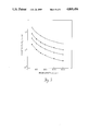
- FIG. 3 is a graph of the calculated sensor sensitivity (R x ) versus beam length (L) for 4 different beam thicknesses.
- FIGS. 4a through 4e illustrate the major processing steps for the fabrication of the embodiment in FIGS. 1a and 1b.
- FIG. 5 is a schematic of the mask used for sample mass etching in the processing steps of FIGS. 4a-4e.
- FIG. 6 is an electrical schematic of the accelerometer of FIGS. 1a and 1b.
- FIG. 7 is an electrical schematic of the electrical circuit used in the accelerometer of FIGS. 1a and 1b.
- FIG. 8 is a perspective view of an alternative embodiment of the invention in which additional constraining arms suppress rotation of the sample mass.
- FIG. 9 is a cross-section of an alternative embodiment which measures acceleration in three directions.
- FIG. 10 is a cross-section of another alternative embodiment which measures acceleration in three directions.
- FIGS. 1a and 1b An accelerometer 25 embodying the present invention is shown in FIGS. 1a and 1b.
- a sample mass or weight 11 is suspended within a centrally located opening 26 in a substrate 28.
- Weight 11 is suspended by four beams 32, 34, 36 and 38 which longitudinally bridge across opening 26 between substrate 28 and weight 11 and lie within respective slots 18, 29, 47, 49 of substrate 28.
- Beams 32 and 36 lie opposite each other across weight 11 and lie on a common axis which is labelled the y-axis for illustration in FIG. 1a.
- Beams 34 and 38 similarly lie opposite each other across weight 11 but on an x-axis perpendicular to the y-axis.
- each set of drive 10, 20, 30, 40 and sense 21, 22, 23, 24 electrodes are capacitively coupled to the four beams 32, 34, 36, 38, one set to a beam.
- FIG. 1b a cross-section along the x-axis of FIG. 1a, each set of drive and sense electrodes lies across gap 43 from a respective beam. Further, each set of sense and drive electrodes bridges laterally across the respective beam as shown in FIGS. 1a and 1c. End regions of each electrode are supported by respective edges of substrate 28 which form slots 18, 29, 47 and 49.
- FIG. 1c is a cross-section through drive electrode 30 along line Ic--Ic of FIG. 1a.
- Drive electrodes 20, 10, 40 and respective beams 36, 38 and 32 are similarly positioned about slots 47, 49 and 18, respectively, of substrate 28 in FIG. 1a.
- the beams 32, 34, 36 and 38 are resonated at respective fixed resonant frequencies through the respective sense 24, 23, 22, 21 and drive electrodes 40, 30, 20, 10 as is discussed later.
- beam 38 becomes compressed while beam 34 is stretched. Consequently, the resonant frequency associated with beam 38 decreases and that associated with beam 34 increases.
- the difference of the two changed resonant frequencies is used as the sensor 25 output.
- the difference of the two resonant frequencies before and after acceleration of weight 11 and substrate 28 provides a change in differential resonant frequency between beams along a common axis. The magnitude of this change is the magnitude of the sensed acceleration and the associated axis provides the direction of the sensed acceleration.
- Negative x-direction acceleration is similarly detected where beam 38 is stretched and beam 34 is compressed, and the resonant frequency of beam 38 increases and that of beam 34 decreases. Similar detection of positive and negative y-direction acceleration is provided by the symmetrical stretching and compressing of beams 32 and 36, and by the changing of their respective resonant frequencies.
- a frequency measuring circuit is connected to each beam (not shown here).
- a frequency measuring circuit as is known in the art and referenced in Paul Horowitz and Winfield Hill, "The Art of Electronics", Cambridge University Press, 1980, pgs. 617-620, such as a frequency counter or a phase locked loop, is suitable. Such a frequency measuring circuit is herein incorporated by reference.
- Each frequency measuring circuit provides a signal processing circuit with a measured frequency of a beam. The signal processing circuit then provides the difference in measured frequencies between beams along a common axis as an indication of acceleration along the common axis.
- the differential frequency detection scheme is mathematically based on a Taylor expansion of resonant frequency calculated by Rayleigh's Energy Method.
- Resonant frequency (f) is solved for in Rayleigh's Energy Method by equating maximum potential energy of vibration to the maximum kinetic energy. Applying this method to a bridge under axial tension, as in beams 34 and 38 in the foregoing example of a positive x-direction acceleration, the following results.
- the potential energy of each beam will contain terms due to both bending and axial tension.
- the maximum bending potential energy, U B of a beam is expressed as ##EQU1## where L is the length of the beam, w(x) is the envelope function or mode shape of the beam, E is modulus of elasticity, and I is the beam cross-section moment of inertia.
- the product EI represents the flexural rigidity for bending.
- the maximum potential energy due to axial tension or the stretching strain energy U st of the beam is expressed as ##EQU2## where M is the mass of weight 11, and A x is acceleration along the x-axis.
- ⁇ specific density of beam material
- b and t are width and thickness, respectively of the beam
- f resonant frequency of the beam.
- the first mode shape w 1 (x) for a vibrating bridge is tabulated in C. M. Harris and C. E. Crede, "Shock and Vibration Handbook", McGraw-Hill, 1961, pp. 7-13, 7-14 and is incorporated herein by reference.
- the unperturbed resonant frequency f 0 is then
- f 01 is the unperturbed resonant frequency of arm 34 and the coefficients k ij are determined by the physical properties and geometrical dimensions of arm 34.
- arm 38 which experiences compression due to the positive x-direction acceleration A x has resonant frequency
- f 02 is the unperturbed resonant frequency of arm 38 and coefficients k ij are determined by the physical properties and geometrical dimensions of arm 38.
- the zero order term (f 01 -f 02 ) and even order terms (e.g., k 21 -k 22 ) are made very small by the high degree of matching dimensions and properties of beam pair members through micromachining techniques used to fabricate sensor 25.
- acceleration A x may be computed by relating the measured frequency difference between beam pair members to respective odd order terms (e.g. k 11 +k 12 ) and the mass of weight 11. Further, the output signal of ⁇ f is nearly a linear function of the acceleration A x except for some perturbation from the higher order terms.
- differential detection scheme Another advantage of the differential detection scheme is that small effects due to random vertical vibration (z-direction) are factors in the resonant frequency equation of each beam and are subtracted from themselves during the calculation of the differential output ⁇ f. Thermal effects are similarly common to all beam resonant frequencies and are mostly rejected by the differential mode of detection.
- the differential detection scheme thus solves the problems of z-direction acceleration or non-signal motions affecting x and y-direction acceleration measurements and temperature effects found in prior art devices.
- Sensitivity R in a direction along a major axis of a beam is defined as
- Sensitivity does not depend on beam length L.
- L can be selected to set the resonant frequency f 0 of equation (5) or dynamic range A max of equation (11).
- Sensitivity is proportional to (bt 2 ) -1 , but the dynamic range of acceleration (A max ) is proportional to (bt 3 ). Hence, there is a trade-off between high sensitivity and wide dynamic range.
- the beam material is either polycrystalline silicon doped with phosphorus or single crystal silicon doped with boron.
- the drive and sense electrode material is a phosphorus-doped polycrystalline silicon.
- the weight 11 is made of a slab of single crystal silicon shaped by orientation-dependent wet chemical etching. A detailed discussion on shaping of the weight is presented later.
- FIG. 2 is a plot of equation (5) of the unperturbed resonant frequency f o versus beam length L with four different beam thicknesses.
- L/b ratio of beam length to beam width
- Length of beams (L) 200 ⁇ m, 150 ⁇ m, 100 ⁇ m
- Width of beams (b) 20 ⁇ m, 15 ⁇ m, 10 ⁇ m
- Thickness of beams (t) 1 ⁇ m
- the beam resonant frequency is
- the sensitivity is
- FIGS. 4a-4e are cross-sections along a common longitudinal axis of a pair of beams.
- a 4 ⁇ m thick heavy boron doped layer 12 with doping concentration greater than 5 ⁇ 10 19 cm -3 is formed over a silicon wafer 41 by ion implantation or diffusion as shown in FIG. 4a.
- This layer 12 is later used as the etch-stop in the shaping of the weight and beam formation process.
- Layer 12 is also used to support end regions of the electrodes.
- the doped layer 12 is activated, by thermal annealing in this case, and a 5000 ⁇ thick layer of SiO 2 is thermally grown at 13 in FIG. 4a.
- polySi I polycrystalline silicon
- LPCVD low pressure chemical vapor deposition
- the four beams are delineated into the polySi I layer 14 by plasma etching using sulfur hexafluoride (SF 6 ) as shown in FIG. 4b.
- SF 6 sulfur hexafluoride
- PSG phosphosilicate glass
- the PSG pedestal 15 is used to define the suspended length of the drive (10, 20, 30, 40) and sense (21, 22, 23, 24) electrodes which bridge over respective beams 38, 36, 34, 32 of FIG. 1a and their spacing with respect to the resonant beams delineated into layer 14.
- a second layer 16 of polySi (polySi II) with a thickness of 1 ⁇ m is deposited on top of the PSG pedestal 15, and the drive and sense electrodes are delineated into this layer 16 in FIG. 4d.
- Contact holes through the PSG pedestal 15 to the polySi I layer 14 are opened and a 1 ⁇ m thick aluminum layer is deposited through the contact holes to the polySi I layer 14 and delineated to form metal bonding pads on each beam.
- the shaping of the weight 11 is accomplished through the backside of the wafer 41 using an orientation-dependent wet chemical etching technique with EDP as the etchant.
- EDP orientation-dependent wet chemical etching
- the front side of the wafer 41 is coated with a masking film.
- a corner compensation scheme is used. In this scheme, a regularly used masking SiO 2 square 52 (for defining a square shaped device) is modified by adding an extra SiO 2 square 53, 55, 57, 59 to each of its corners, as shown in FIG. 5.
- the wafer 41 is dipped into BHF to remove the remaining thermal SiO 2 layer 13 and PSG spacer 15 (FIG. 4e). The masking film on the front side of wafer 41 is also removed. In order to keep the weight mass 11 from frictional contact with the support, properly positioned cavities are etched in another silicon wafer 19, and the wafer 19 is bonded to the device wafer 41 to form a support as shown in the lower part of FIG. 4e. Electrodes may then be deposited on wafer 19 for means for measuring perpendicular acceleration.
- the control of residual stress in thin films is achieved by modifications in the film deposition conditions and by annealing. Annealing is effective in relaxing residual stress in polysilicon films.
- the requisite high temperature of greater than 1050° C. are undesirable in a fabrication process that includes active electronic devices because of excessive dopant redistribution.
- some designs of the present invention may choose off-chip circuitry over on-chip circuitry.
- the drive of the beams and detection of beam vibration can be accomplished using a variety of methods.
- excitation may be accomplished by thermal expansion, piezoelectric films as well as by capacitive electrostatics as disclosed and incorporated herein by reference in
- the capactive approach has an advantage for resonant microsensors. Given a conducting microstructure, electrostatic fields can exert drive forces and enable detection of changes in electrode spacing without modification of the resonating element. In contrast to the other methods, there is no need to incorporate diffusions for heat resistors or piezoelectric films and electrodes into the microstructure. The simplicity of this structural design also makes it easier to control stress and solve potential fatigue problems.
- beams 32, 34, 36, 38 are resonated by applying a dc bias voltage V p and a sinusoidal drive voltage V d to respective drive electrodes 40, 30, 20, 10.
- An electronic schematic of beams 34 and 38 is provided in FIG. 6.
- An electrostatic force is activated across the thin gaps 43 formed between the respective drive electrodes and beams. Gap 43 must be thin enough to support an electric field with a strength large enough to excite the beams. This is accomplished through the surface micromachining techniques previously described.
- each drive electrode 40, 30, 20, 10 is positioned at a midpoint of the length of its respective beam 32, 34, 36 38 to obtain a fundamental harmonic in the excitation of each beam.
- different positioning and excitation of the drive electrodes is capable of obtaining higher harmonics.
- Vibration of each beam causes capacitance of gap 43 to be time-varying, and thereby generates a current i s equal to ##EQU6## where V s is the voltage produced by i s , and the capacitance between each sense electrode and respective beam is C s/ 2 .
- the sense electrodes of each beam detect the time-varying capacitance C s and thus detect the respective beam deflection or vibration since C s is proportional to the deflection/vibration.
- the sensed movement of the beam is measured in a feedback circuit which sets voltage V d of the respective drive electrode equal to the resonant frequency of the beam. A self-sustained oscillation of the beam is thus achieved and maintained for each beam through the respective sense and drive electrodes of the beam.
- the sensed current i s is measured by respective ammeters of each beam illustrated in FIG. 6 as ammeters 17 and 27 of beams 34 and 38 respectively.
- the sensed current i s is converted into a V d voltage signal, amplified and buffered using an on-chip NMOS circuit 43 shown in FIG. 7.
- Neglecting parasitic and device capacitances, i s produces a sensed voltage V s proportional to i s /g ml at the gate of the transistor M 3 where g ml is the gain of amplifier M 1 .
- Transistors M 4 , M 5 , and M 6 constitute a standard NMOS active load for transistor M 3 that minimizes gain degradation due to the body effect.
- a source-follower stage buffers the output sensed voltage V s .
- the output of the device 25 is preferrably accomplished by a signal processor circuit 72 shown in FIG. 6.
- the frequency measuring circuit of each beam (shown as 68, 70 for beams 34, 38 respectively) detects the frequency of the respective drive electrode voltage V d .
- the difference between detected frequencies of beams along a common axis is then produced in signal processor circuit 72 which in turn provides an indication of acceleration as a function of the sensed frequency difference.
- circuits which involve counters, digital means, or the like for measuring the frequency of voltage V d for each beam are suitable.
- digital means a user or computer system can directly calculate the frequency difference to provide an output of accelerometer 25.
- Finite element analysis indicates that the embodiment of FIGS. 1a and 1b is limited in dynamic range due to rotation of the weight 11, which causes the resonating beams 32, 34, 36, 38 to contrast the sense electrodes 21, 22, 23, 24 at lower acceleration A x than predicted by equation (11).
- An improved accelerometer design is illustrated in FIG. 8, in which four additional constraining arms or bridges 64 have been micromachined on the backside 45 of the silicon wafer 66.
- Finite element analysis indicates that the constraining bridges 64 suppress rotation and thereby increase the dynamic range.
- the improved design is predicted to have higher sensitivity R x .
- the 4 ⁇ m-thick constraining bridges 64 are fabricated by means of an additional masked boron implant on the backside 45 of the wafer 66. This implant is performed after the partial anneal of the front side boron etch-stop implant of FIG. 4a. Undercutting of the backside boron-doped regions occurs during shaping of the weight which forms the constraining bridges 64.
- the resonant arms 62, sample mass 60, sense and drive electrodes referenced by S and D respectively in FIG. 8 are fabricated and operate in the same manner as respective parts in accelerometer 25 of FIGS. 1a and 1b.
- Beams 32 and 36 of FIG. 1a provide a measurement of acceleration along the y-axis and beams 34 and 38 provide a measurement along the x-axis. Measurement along a third direction may be provided by sandwiching the accelerometer of FIG. 1a or 8 between mountings 74 and 76 shown in FIG. 9.
- Mountings 74 and 76 preferably comprise pyrex or silicon wafers and have cavities etched in facing sides so as to allow movement of the proof mass 11, and beams 32, 34, 36, 38 and constraining bridges 64 if any.
- At least one additional beam 78 is positioned between any two of the beams 32, 34, 36 or 38 and similarly bridges between substrate 28 and proof mass 11. Deflection of additional beam 78 is measured in a similar manner that cantilever beams in prior art accelerometers are measured as described and incorporated herein by reference in
- the measurement provides an indication of acceleration in a direction perpendicular to the longitudinal axis of beam 78, that is in a z-direction as shown in FIG. 9.
- bridges 64 would be capacitively coupled to mounting 76. A measurement of the change in capacity would provide an indication of the deflection of bridges 64 and thereby acceleration of device 25 in the z-direction.
- the capacitance measuring techniques of the foregoing references similarly apply to the measurement of deflection of bridges 64 or displacement of weight 11.
- An alternative technique for measuring perpendicular acceleration is to use electrodes 80, 82 and 84 on weight 11 and mountings 74 and 76, respectively, to couple an electrostatic force that cancels the displacement of the weight.
- the deflection of weight 11 is sensed by additional arms 78 or bridges 64 as described above.
- a feedback amplifier converts the detected signals into amplified voltages that are applied across drive electrodes 82 and drive electrodes 84 on supports 74 and 76 respectively, in order to null the displacement of weight 11.
- One of the applied voltages provides the output signal indicating perpendicular acceleration.
Abstract
Description
f.sub.0 =1.03(E/.sub.ρ).sup.1/2 (t/L.sup.2) (5)
f.sub.1 =f.sub.0 [1+0.293(L.sup.2 /Ebt.sup.3)(1/2MA.sub.x)].sup.1/2(6)
f.sub.1 =f.sub.01 -k.sub.11 (MA.sub.x)+k.sub.21 (MA.sub.x).sup.2 -k.sub.31 (MA.sub.x).sup.3 +. . . (7)
f.sub.2 =f.sub.02 -k.sub.12 (MA.sub.x)+k.sub.22 (MA.sub.x).sup.2 -k.sub.32 (MA.sub.x).sup.3 +. . . (8)
Δf=f.sub.1 -f.sub.2 =(f.sub.01 -f.sub.02)+(k.sub.11 +k.sub.12)(MA.sub.x)+(k.sub.21 -k.sub.22)(MA.sub.x).sup.2 +(k.sub.31 +k.sub.32)(MA.sub.x).sup.3 +. . . (9)
f-f.sub.0 =RA
F.sub.c =4π.sup.2 EI/L.sup.2,
hence
1/2MA.sub.x ≦4π.sup.2 EI/L.sup.2,
and
A.sub.x,max =2π.sup.2 Ebt.sup.3 /3L.sup.2 M (11)
R.sub.x =24000/Lt.sup.2 (Hz/ms.sup.-2)
A.sub.max =1.64×10.sup.15 t.sup.3 /L
200 KHz≦f.sub.o ≦800 KHz
1.1(KHz/G)≦R.sub.x ≦2.4(KHz/G)
80 G≦A.sub.max ≦160 G.
Claims (35)
Priority Applications (1)
| Application Number | Priority Date | Filing Date | Title |
|---|---|---|---|
| US07/052,026 US4805456A (en) | 1987-05-19 | 1987-05-19 | Resonant accelerometer |
Applications Claiming Priority (1)
| Application Number | Priority Date | Filing Date | Title |
|---|---|---|---|
| US07/052,026 US4805456A (en) | 1987-05-19 | 1987-05-19 | Resonant accelerometer |
Publications (1)
| Publication Number | Publication Date |
|---|---|
| US4805456A true US4805456A (en) | 1989-02-21 |
Family
ID=21974947
Family Applications (1)
| Application Number | Title | Priority Date | Filing Date |
|---|---|---|---|
| US07/052,026 Expired - Fee Related US4805456A (en) | 1987-05-19 | 1987-05-19 | Resonant accelerometer |
Country Status (1)
| Country | Link |
|---|---|
| US (1) | US4805456A (en) |
Cited By (97)
| Publication number | Priority date | Publication date | Assignee | Title |
|---|---|---|---|---|
| WO1989008336A1 (en) * | 1988-02-29 | 1989-09-08 | The Regents Of The University Of California | Plate-mode ultrasonic sensor |
| US4901570A (en) * | 1988-11-21 | 1990-02-20 | General Motors Corporation | Resonant-bridge two axis microaccelerometer |
| US4922756A (en) * | 1988-06-20 | 1990-05-08 | Triton Technologies, Inc. | Micro-machined accelerometer |
| US4945765A (en) * | 1988-08-31 | 1990-08-07 | Kearfott Guidance & Navigation Corp. | Silicon micromachined accelerometer |
| US4945773A (en) * | 1989-03-06 | 1990-08-07 | Ford Motor Company | Force transducer etched from silicon |
| WO1990010205A1 (en) * | 1989-02-27 | 1990-09-07 | Sundstrand Data Control, Inc. | Electrostatically driven dual vibrating beam force transducer |
| JPH02248867A (en) * | 1989-03-23 | 1990-10-04 | Toyo Commun Equip Co Ltd | Acceleration sensor |
| US5034891A (en) * | 1989-11-03 | 1991-07-23 | Trw Vehicle Safety Systems Inc. | Method and apparatus for sensing a vehicle crash with frequency domain boost |
| US5036467A (en) * | 1990-04-04 | 1991-07-30 | Trw Vehicle Safety Systems Inc. | Method and apparatus for sensing a vehicle crash in real time using a frequency domain integration and summation algorithm |
| US5039170A (en) * | 1990-06-20 | 1991-08-13 | Reno Salvage Co. | Resonant beam suspension pads |
| US5045152A (en) * | 1989-03-06 | 1991-09-03 | Ford Motor Company | Force transducer etched from silicon |
| US5065322A (en) * | 1990-04-04 | 1991-11-12 | Trw Vehicle Safety Systems Inc. | Method and apparatus for sensing a vehicle crash in real time using a frequency domain summation algorithm |
| US5073860A (en) * | 1989-11-07 | 1991-12-17 | Trw Vehicle Safety Systems Inc. | Method and apparatus for sensing a vehicle crash in real time using frequency domain analysis |
| US5090254A (en) * | 1990-04-11 | 1992-02-25 | Wisconsin Alumni Research Foundation | Polysilicon resonating beam transducers |
| US5126812A (en) * | 1990-02-14 | 1992-06-30 | The Charles Stark Draper Laboratory, Inc. | Monolithic micromechanical accelerometer |
| US5129983A (en) * | 1991-02-25 | 1992-07-14 | The Charles Stark Draper Laboratory, Inc. | Method of fabrication of large area micromechanical devices |
| US5144184A (en) * | 1990-01-26 | 1992-09-01 | The Charles Stark Draper Laboratory, Inc. | Micromechanical device with a trimmable resonant frequency structure and method of trimming same |
| US5185701A (en) * | 1989-11-03 | 1993-02-09 | Trw Vehicle Safety Systems Inc. | Method for determining frequency components in a vehicle crash |
| US5188983A (en) * | 1990-04-11 | 1993-02-23 | Wisconsin Alumni Research Foundation | Polysilicon resonating beam transducers and method of producing the same |
| US5189914A (en) * | 1988-02-29 | 1993-03-02 | The Regents Of The University Of California | Plate-mode ultrasonic sensor |
| US5203208A (en) * | 1991-04-29 | 1993-04-20 | The Charles Stark Draper Laboratory | Symmetrical micromechanical gyroscope |
| US5212988A (en) * | 1988-02-29 | 1993-05-25 | The Reagents Of The University Of California | Plate-mode ultrasonic structure including a gel |
| US5216490A (en) * | 1988-01-13 | 1993-06-01 | Charles Stark Draper Laboratory, Inc. | Bridge electrodes for microelectromechanical devices |
| US5233874A (en) * | 1991-08-19 | 1993-08-10 | General Motors Corporation | Active microaccelerometer |
| US5233871A (en) * | 1991-11-01 | 1993-08-10 | Delco Electronics Corporation | Hybrid accelerometer assembly |
| US5331852A (en) * | 1991-09-11 | 1994-07-26 | The Charles Stark Draper Laboratory, Inc. | Electromagnetic rebalanced micromechanical transducer |
| US5349855A (en) * | 1992-04-07 | 1994-09-27 | The Charles Stark Draper Laboratory, Inc. | Comb drive micromechanical tuning fork gyro |
| US5352635A (en) * | 1990-07-12 | 1994-10-04 | Tu Xiang Zheng | Silicon accelerometer fabrication method |
| US5408119A (en) * | 1990-10-17 | 1995-04-18 | The Charles Stark Draper Laboratory, Inc. | Monolithic micromechanical vibrating string accelerometer with trimmable resonant frequency |
| US5408877A (en) * | 1992-03-16 | 1995-04-25 | The Charles Stark Draper Laboratory, Inc. | Micromechanical gyroscopic transducer with improved drive and sense capabilities |
| US5415726A (en) * | 1993-12-21 | 1995-05-16 | Delco Electronics Corporation | Method of making a bridge-supported accelerometer structure |
| US5456111A (en) * | 1994-01-24 | 1995-10-10 | Alliedsignal Inc. | Capacitive drive vibrating beam accelerometer |
| US5461918A (en) * | 1993-04-26 | 1995-10-31 | Ford Motor Company | Vibrating beam accelerometer |
| US5484073A (en) * | 1994-03-28 | 1996-01-16 | I/O Sensors, Inc. | Method for fabricating suspension members for micromachined sensors |
| EP0737864A1 (en) * | 1995-04-12 | 1996-10-16 | Sensonor A.S. | Force sensor |
| US5581035A (en) * | 1994-08-29 | 1996-12-03 | The Charles Stark Draper Laboratory, Inc. | Micromechanical sensor with a guard band electrode |
| US5605598A (en) * | 1990-10-17 | 1997-02-25 | The Charles Stark Draper Laboratory Inc. | Monolithic micromechanical vibrating beam accelerometer with trimmable resonant frequency |
| US5635739A (en) * | 1990-02-14 | 1997-06-03 | The Charles Stark Draper Laboratory, Inc. | Micromechanical angular accelerometer with auxiliary linear accelerometer |
| US5635639A (en) * | 1991-09-11 | 1997-06-03 | The Charles Stark Draper Laboratory, Inc. | Micromechanical tuning fork angular rate sensor |
| US5646348A (en) * | 1994-08-29 | 1997-07-08 | The Charles Stark Draper Laboratory, Inc. | Micromechanical sensor with a guard band electrode and fabrication technique therefor |
| US5650568A (en) * | 1993-02-10 | 1997-07-22 | The Charles Stark Draper Laboratory, Inc. | Gimballed vibrating wheel gyroscope having strain relief features |
| US5725729A (en) * | 1994-09-26 | 1998-03-10 | The Charles Stark Draper Laboratory, Inc. | Process for micromechanical fabrication |
| US5736430A (en) * | 1995-06-07 | 1998-04-07 | Ssi Technologies, Inc. | Transducer having a silicon diaphragm and method for forming same |
| US5744717A (en) * | 1995-07-06 | 1998-04-28 | Robert Bosch Gmbh | Circuit arrangement for a capacitive acceleration sensor |
| US5767405A (en) * | 1992-04-07 | 1998-06-16 | The Charles Stark Draper Laboratory, Inc. | Comb-drive micromechanical tuning fork gyroscope with piezoelectric readout |
| US5783973A (en) * | 1997-02-24 | 1998-07-21 | The Charles Stark Draper Laboratory, Inc. | Temperature insensitive silicon oscillator and precision voltage reference formed therefrom |
| US5801309A (en) * | 1994-03-18 | 1998-09-01 | New Jersey Institute Of Technology | Microaccelerometer employing resonant circuit detection of seismic mass displacement |
| US5817942A (en) * | 1996-02-28 | 1998-10-06 | The Charles Stark Draper Laboratory, Inc. | Capacitive in-plane accelerometer |
| JP2808969B2 (en) | 1992-03-19 | 1998-10-08 | 日本電気株式会社 | Manufacturing method of semiconductor acceleration sensor |
| US5834333A (en) * | 1995-06-07 | 1998-11-10 | Ssi Technologies, Inc. | Transducer having a resonating silicon beam and method for forming same |
| US5852242A (en) * | 1995-12-04 | 1998-12-22 | I/O Sensors, Inc. | Apparatus with mechanical and electric springs and method for its manufacture |
| US5892153A (en) * | 1996-11-21 | 1999-04-06 | The Charles Stark Draper Laboratory, Inc. | Guard bands which control out-of-plane sensitivities in tuning fork gyroscopes and other sensors |
| US5911156A (en) * | 1997-02-24 | 1999-06-08 | The Charles Stark Draper Laboratory, Inc. | Split electrode to minimize charge transients, motor amplitude mismatch errors, and sensitivity to vertical translation in tuning fork gyros and other devices |
| US5952574A (en) * | 1997-04-29 | 1999-09-14 | The Charles Stark Draper Laboratory, Inc. | Trenches to reduce charging effects and to control out-of-plane sensitivities in tuning fork gyroscopes and other sensors |
| US5998906A (en) * | 1998-01-13 | 1999-12-07 | Seagate Technology, Inc. | Electrostatic microactuator and method for use thereof |
| US6021675A (en) * | 1995-06-07 | 2000-02-08 | Ssi Technologies, Inc. | Resonating structure and method for forming the resonating structure |
| US6134207A (en) * | 1996-07-30 | 2000-10-17 | Seagate Technology, Inc. | Optical data storage system having optical microswitch |
| US6257062B1 (en) | 1999-10-01 | 2001-07-10 | Delphi Technologies, Inc. | Angular Accelerometer |
| US6311556B1 (en) * | 1997-05-23 | 2001-11-06 | Sextant Avionique | Micro-accelerometer with capacitive resonator |
| US6324910B1 (en) * | 1996-10-21 | 2001-12-04 | Robert Bosch Gmbh | Method and device for measuring a physical variable |
| US6360035B1 (en) | 1996-07-30 | 2002-03-19 | Seagate Technology Llc | Optical head using micro-machined elements |
| US6393914B1 (en) | 2001-02-13 | 2002-05-28 | Delphi Technologies, Inc. | Angular accelerometer |
| US6666092B2 (en) | 2002-02-28 | 2003-12-23 | Delphi Technologies, Inc. | Angular accelerometer having balanced inertia mass |
| US20040027033A1 (en) * | 2002-08-08 | 2004-02-12 | Schiller Peter J. | Solid-state acceleration sensor device and method |
| US20040035206A1 (en) * | 2002-03-26 | 2004-02-26 | Ward Paul A. | Microelectromechanical sensors having reduced signal bias errors and methods of manufacturing the same |
| US6718826B2 (en) | 2002-02-28 | 2004-04-13 | Delphi Technologies, Inc. | Balanced angular accelerometer |
| US6761070B2 (en) | 2002-01-31 | 2004-07-13 | Delphi Technologies, Inc. | Microfabricated linear accelerometer |
| US6836584B1 (en) | 1998-01-13 | 2004-12-28 | Iolon, Inc. | Optical microswitch |
| US20050240374A1 (en) * | 2004-04-27 | 2005-10-27 | Zarabadi Seyed R | Circuit and method of processing multiple-axis sensor output signals |
| US20050235751A1 (en) * | 2004-04-27 | 2005-10-27 | Zarabadi Seyed R | Dual-axis accelerometer |
| US20060207328A1 (en) * | 2005-03-16 | 2006-09-21 | Zarabadi Seyed R | Multiple-axis linear accelerometer |
| US20060211161A1 (en) * | 2005-03-16 | 2006-09-21 | Christenson John C | Method of making microsensor |
| US20060255790A1 (en) * | 2005-02-14 | 2006-11-16 | Clemson University | Method and apparatus for detecting resonance in electrostatically driven elements |
| US20080028823A1 (en) * | 2006-08-01 | 2008-02-07 | Howard Samuels | Sensor Self-Test Transfer Standard |
| US20080223132A1 (en) * | 2004-03-02 | 2008-09-18 | Jiro Terada | Vibration Piezoelectric Acceleration Sensor |
| US20090255339A1 (en) * | 2008-04-14 | 2009-10-15 | Freescale Semiconductor, Inc. | Resonant accelerometer with low sensitivity to package stress |
| US20090320595A1 (en) * | 2007-12-10 | 2009-12-31 | Electronics And Telecommunications Research Institute | Micromachined sensor for measuring vibration |
| US20100005884A1 (en) * | 2008-07-09 | 2010-01-14 | Weinberg Marc S | High Performance Sensors and Methods for Forming the Same |
| US20100267241A1 (en) * | 2007-12-21 | 2010-10-21 | Solvay Fluor Gmbh | Process for the production of microelectromechanical systems |
| US20110105955A1 (en) * | 2009-11-03 | 2011-05-05 | Medtronic Minimed, Inc. | Omnidirectional accelerometer device and medical device incorporating same |
| US8384372B1 (en) | 2005-02-14 | 2013-02-26 | Clemson University | Non-linear electrical actuation and detection |
| US20140102197A1 (en) * | 2007-10-11 | 2014-04-17 | Farrokh Ayazi | Bulk acoustic wave accelerometers |
| US9309106B2 (en) | 2013-07-08 | 2016-04-12 | Motion Engine Inc. | 3D MEMS device and method of manufacturing |
| JP2017015606A (en) * | 2015-07-02 | 2017-01-19 | 多摩川精機株式会社 | Structure for suppressing mutual interference between surface acoustic wave resonators, and acceleration sensor |
| US10214414B2 (en) | 2014-01-09 | 2019-02-26 | Motion Engine, Inc. | Integrated MEMS system |
| US10273147B2 (en) | 2013-07-08 | 2019-04-30 | Motion Engine Inc. | MEMS components and method of wafer-level manufacturing thereof |
| US10407299B2 (en) | 2015-01-15 | 2019-09-10 | Motion Engine Inc. | 3D MEMS device with hermetic cavity |
| US10432167B2 (en) * | 2016-04-01 | 2019-10-01 | Intel Corporation | Piezoelectric package-integrated crystal devices |
| US10545167B2 (en) | 2015-10-20 | 2020-01-28 | Analog Devices, Inc. | Multiple-axis resonant accelerometers |
| US10768065B2 (en) | 2014-04-10 | 2020-09-08 | Mei Micro, Inc. | MEMS pressure sensor |
| US10894713B2 (en) * | 2004-10-08 | 2021-01-19 | Stmicroelectronics S.R.L. | Temperature-compensated micro-electromechanical device, and method of temperature compensation in a micro-electromechanical device |
| WO2022036457A1 (en) * | 2020-08-20 | 2022-02-24 | Boss Packaging Inc. | Wireless sensor unit |
| US11275099B1 (en) * | 2018-07-20 | 2022-03-15 | Hrl Laboratories, Llc | Navigational grade resonant MicroElectroMechanical Systems (mems) accelerometer and method of operation |
| US11287486B2 (en) | 2014-12-09 | 2022-03-29 | Motion Engine, Inc. | 3D MEMS magnetometer and associated methods |
| US11573137B2 (en) * | 2017-09-20 | 2023-02-07 | Asahi Kasei Kabushiki Kaisha | Surface stress sensor, hollow structural element, and method for manufacturing same |
| US11674803B2 (en) | 2014-06-02 | 2023-06-13 | Motion Engine, Inc. | Multi-mass MEMS motion sensor |
| US11852481B2 (en) | 2013-08-02 | 2023-12-26 | Motion Engine Inc. | MEMS motion sensor and method of manufacturing |
Citations (4)
| Publication number | Priority date | Publication date | Assignee | Title |
|---|---|---|---|---|
| US3382724A (en) * | 1965-01-04 | 1968-05-14 | North American Rockwell | Three axis accelerometer |
| US3541866A (en) * | 1967-02-24 | 1970-11-24 | Csf | Vibrating string accelerometers |
| US4517841A (en) * | 1983-01-06 | 1985-05-21 | Sundstrand Data Control, Inc. | Accelerometer with beam resonator force transducer |
| US4699006A (en) * | 1984-03-19 | 1987-10-13 | The Charles Stark Draper Laboratory, Inc. | Vibratory digital integrating accelerometer |
-
1987
- 1987-05-19 US US07/052,026 patent/US4805456A/en not_active Expired - Fee Related
Patent Citations (4)
| Publication number | Priority date | Publication date | Assignee | Title |
|---|---|---|---|---|
| US3382724A (en) * | 1965-01-04 | 1968-05-14 | North American Rockwell | Three axis accelerometer |
| US3541866A (en) * | 1967-02-24 | 1970-11-24 | Csf | Vibrating string accelerometers |
| US4517841A (en) * | 1983-01-06 | 1985-05-21 | Sundstrand Data Control, Inc. | Accelerometer with beam resonator force transducer |
| US4699006A (en) * | 1984-03-19 | 1987-10-13 | The Charles Stark Draper Laboratory, Inc. | Vibratory digital integrating accelerometer |
Non-Patent Citations (12)
| Title |
|---|
| J. C. Greenwood, "Etched Silicon Vibrating Sensor", Journal of Physics E:Scientific Instrumentation, vol. 17, pp. 650-652, 1984. |
| J. C. Greenwood, Etched Silicon Vibrating Sensor , Journal of Physics E:Scientific Instrumentation, vol. 17, pp. 650 652, 1984. * |
| Martin A. Schmidt and Roger T. Howe, "Silicon Resonant Microsensors", Ceramic Engineering and Science Proceedings, Automotive Materials Conference, Nov. 19, 1986, pp. 1-20. |
| Martin A. Schmidt and Roger T. Howe, Silicon Resonant Microsensors , Ceramic Engineering and Science Proceedings, Automotive Materials Conference, Nov. 19, 1986, pp. 1 20. * |
| P. L. Chen, et al., "Integrated Silicon PI-FET Accelerometer with Proof Mass", Sensors and Actuators, 5:119-126 (1984). |
| P. L. Chen, et al., Integrated Silicon PI FET Accelerometer with Proof Mass , Sensors and Actuators, 5:119 126 (1984). * |
| P. W. Barth, "Silicon Sensors Meet Integrated Circuits", 8045 IEEE Spectrum, vol. 18 (1981), pp. 33-39. |
| P. W. Barth, Silicon Sensors Meet Integrated Circuits , 8045 IEEE Spectrum, vol. 18 (1981), pp. 33 39. * |
| Roger T. Howe and Richard S. Muller, "Resonant-Microbridge Vapor Sensor", IEEE Transactions on Electron Devices, vol. ED-33, No. 4, Apr. 1986, pp. 499-506. |
| Roger T. Howe and Richard S. Muller, Resonant Microbridge Vapor Sensor , IEEE Transactions on Electron Devices, vol. ED 33, No. 4, Apr. 1986, pp. 499 506. * |
| William C. Albert, "Vibrating Quartz Crystal Beam Accelerometer", 28th Instrument Society of America International Instrumentation Symposium, Proceedings, 1982, pp. 33-44. |
| William C. Albert, Vibrating Quartz Crystal Beam Accelerometer , 28th Instrument Society of America International Instrumentation Symposium, Proceedings, 1982, pp. 33 44. * |
Cited By (124)
| Publication number | Priority date | Publication date | Assignee | Title |
|---|---|---|---|---|
| US5216490A (en) * | 1988-01-13 | 1993-06-01 | Charles Stark Draper Laboratory, Inc. | Bridge electrodes for microelectromechanical devices |
| WO1989008336A1 (en) * | 1988-02-29 | 1989-09-08 | The Regents Of The University Of California | Plate-mode ultrasonic sensor |
| US5189914A (en) * | 1988-02-29 | 1993-03-02 | The Regents Of The University Of California | Plate-mode ultrasonic sensor |
| US5212988A (en) * | 1988-02-29 | 1993-05-25 | The Reagents Of The University Of California | Plate-mode ultrasonic structure including a gel |
| US4922756A (en) * | 1988-06-20 | 1990-05-08 | Triton Technologies, Inc. | Micro-machined accelerometer |
| US4945765A (en) * | 1988-08-31 | 1990-08-07 | Kearfott Guidance & Navigation Corp. | Silicon micromachined accelerometer |
| US4901570A (en) * | 1988-11-21 | 1990-02-20 | General Motors Corporation | Resonant-bridge two axis microaccelerometer |
| WO1990010205A1 (en) * | 1989-02-27 | 1990-09-07 | Sundstrand Data Control, Inc. | Electrostatically driven dual vibrating beam force transducer |
| US4945773A (en) * | 1989-03-06 | 1990-08-07 | Ford Motor Company | Force transducer etched from silicon |
| US5045152A (en) * | 1989-03-06 | 1991-09-03 | Ford Motor Company | Force transducer etched from silicon |
| EP0391512A1 (en) * | 1989-03-06 | 1990-10-10 | Ford Motor Company Limited | Force transducer etched from silicon, and method of producing the same |
| JP2732287B2 (en) | 1989-03-23 | 1998-03-25 | 東洋通信機株式会社 | Acceleration sensor |
| JPH02248867A (en) * | 1989-03-23 | 1990-10-04 | Toyo Commun Equip Co Ltd | Acceleration sensor |
| US5034891A (en) * | 1989-11-03 | 1991-07-23 | Trw Vehicle Safety Systems Inc. | Method and apparatus for sensing a vehicle crash with frequency domain boost |
| US5185701A (en) * | 1989-11-03 | 1993-02-09 | Trw Vehicle Safety Systems Inc. | Method for determining frequency components in a vehicle crash |
| US5073860A (en) * | 1989-11-07 | 1991-12-17 | Trw Vehicle Safety Systems Inc. | Method and apparatus for sensing a vehicle crash in real time using frequency domain analysis |
| US5144184A (en) * | 1990-01-26 | 1992-09-01 | The Charles Stark Draper Laboratory, Inc. | Micromechanical device with a trimmable resonant frequency structure and method of trimming same |
| US5635739A (en) * | 1990-02-14 | 1997-06-03 | The Charles Stark Draper Laboratory, Inc. | Micromechanical angular accelerometer with auxiliary linear accelerometer |
| US5126812A (en) * | 1990-02-14 | 1992-06-30 | The Charles Stark Draper Laboratory, Inc. | Monolithic micromechanical accelerometer |
| US5036467A (en) * | 1990-04-04 | 1991-07-30 | Trw Vehicle Safety Systems Inc. | Method and apparatus for sensing a vehicle crash in real time using a frequency domain integration and summation algorithm |
| US5065322A (en) * | 1990-04-04 | 1991-11-12 | Trw Vehicle Safety Systems Inc. | Method and apparatus for sensing a vehicle crash in real time using a frequency domain summation algorithm |
| US5090254A (en) * | 1990-04-11 | 1992-02-25 | Wisconsin Alumni Research Foundation | Polysilicon resonating beam transducers |
| US5188983A (en) * | 1990-04-11 | 1993-02-23 | Wisconsin Alumni Research Foundation | Polysilicon resonating beam transducers and method of producing the same |
| US5039170A (en) * | 1990-06-20 | 1991-08-13 | Reno Salvage Co. | Resonant beam suspension pads |
| US5352635A (en) * | 1990-07-12 | 1994-10-04 | Tu Xiang Zheng | Silicon accelerometer fabrication method |
| US5605598A (en) * | 1990-10-17 | 1997-02-25 | The Charles Stark Draper Laboratory Inc. | Monolithic micromechanical vibrating beam accelerometer with trimmable resonant frequency |
| US5760305A (en) * | 1990-10-17 | 1998-06-02 | The Charles Stark Draper Laboratory, Inc. | Monolithic micromechanical vibrating beam accelerometer with trimmable resonant frequency |
| US5507911A (en) * | 1990-10-17 | 1996-04-16 | The Charles Stark Draper Laboratory, Inc. | Monolithic micromechanical vibrating string accelerometer with trimmable resonant frequency |
| US5969250A (en) * | 1990-10-17 | 1999-10-19 | The Charles Stark Draper Laboratory, Inc. | Micromechanical accelerometer having a peripherally suspended proof mass |
| US5408119A (en) * | 1990-10-17 | 1995-04-18 | The Charles Stark Draper Laboratory, Inc. | Monolithic micromechanical vibrating string accelerometer with trimmable resonant frequency |
| US5129983A (en) * | 1991-02-25 | 1992-07-14 | The Charles Stark Draper Laboratory, Inc. | Method of fabrication of large area micromechanical devices |
| US5203208A (en) * | 1991-04-29 | 1993-04-20 | The Charles Stark Draper Laboratory | Symmetrical micromechanical gyroscope |
| US5233874A (en) * | 1991-08-19 | 1993-08-10 | General Motors Corporation | Active microaccelerometer |
| US5505084A (en) * | 1991-09-11 | 1996-04-09 | The Charles Stark Draper Laboratory, Inc. | Micromechanical tuning fork angular rate sensor |
| US5635639A (en) * | 1991-09-11 | 1997-06-03 | The Charles Stark Draper Laboratory, Inc. | Micromechanical tuning fork angular rate sensor |
| US5331852A (en) * | 1991-09-11 | 1994-07-26 | The Charles Stark Draper Laboratory, Inc. | Electromagnetic rebalanced micromechanical transducer |
| US5233871A (en) * | 1991-11-01 | 1993-08-10 | Delco Electronics Corporation | Hybrid accelerometer assembly |
| US5515724A (en) * | 1992-03-16 | 1996-05-14 | The Charles Stark Draper Laboratory, Inc. | Micromechanical gyroscopic transducer with improved drive and sense capabilities |
| US5408877A (en) * | 1992-03-16 | 1995-04-25 | The Charles Stark Draper Laboratory, Inc. | Micromechanical gyroscopic transducer with improved drive and sense capabilities |
| JP2808969B2 (en) | 1992-03-19 | 1998-10-08 | 日本電気株式会社 | Manufacturing method of semiconductor acceleration sensor |
| US5496436A (en) * | 1992-04-07 | 1996-03-05 | The Charles Stark Draper Laboratory, Inc. | Comb drive micromechanical tuning fork gyro fabrication method |
| US5767405A (en) * | 1992-04-07 | 1998-06-16 | The Charles Stark Draper Laboratory, Inc. | Comb-drive micromechanical tuning fork gyroscope with piezoelectric readout |
| US5349855A (en) * | 1992-04-07 | 1994-09-27 | The Charles Stark Draper Laboratory, Inc. | Comb drive micromechanical tuning fork gyro |
| US5650568A (en) * | 1993-02-10 | 1997-07-22 | The Charles Stark Draper Laboratory, Inc. | Gimballed vibrating wheel gyroscope having strain relief features |
| US5461918A (en) * | 1993-04-26 | 1995-10-31 | Ford Motor Company | Vibrating beam accelerometer |
| US5415726A (en) * | 1993-12-21 | 1995-05-16 | Delco Electronics Corporation | Method of making a bridge-supported accelerometer structure |
| US5456111A (en) * | 1994-01-24 | 1995-10-10 | Alliedsignal Inc. | Capacitive drive vibrating beam accelerometer |
| US5801309A (en) * | 1994-03-18 | 1998-09-01 | New Jersey Institute Of Technology | Microaccelerometer employing resonant circuit detection of seismic mass displacement |
| US5484073A (en) * | 1994-03-28 | 1996-01-16 | I/O Sensors, Inc. | Method for fabricating suspension members for micromachined sensors |
| US5646348A (en) * | 1994-08-29 | 1997-07-08 | The Charles Stark Draper Laboratory, Inc. | Micromechanical sensor with a guard band electrode and fabrication technique therefor |
| US5581035A (en) * | 1994-08-29 | 1996-12-03 | The Charles Stark Draper Laboratory, Inc. | Micromechanical sensor with a guard band electrode |
| US5725729A (en) * | 1994-09-26 | 1998-03-10 | The Charles Stark Draper Laboratory, Inc. | Process for micromechanical fabrication |
| EP0737864A1 (en) * | 1995-04-12 | 1996-10-16 | Sensonor A.S. | Force sensor |
| US6021675A (en) * | 1995-06-07 | 2000-02-08 | Ssi Technologies, Inc. | Resonating structure and method for forming the resonating structure |
| US5834333A (en) * | 1995-06-07 | 1998-11-10 | Ssi Technologies, Inc. | Transducer having a resonating silicon beam and method for forming same |
| US6118164A (en) * | 1995-06-07 | 2000-09-12 | Ssi Technologies, Inc. | Transducer having a resonating silicon beam and method for forming same |
| US5736430A (en) * | 1995-06-07 | 1998-04-07 | Ssi Technologies, Inc. | Transducer having a silicon diaphragm and method for forming same |
| US5744717A (en) * | 1995-07-06 | 1998-04-28 | Robert Bosch Gmbh | Circuit arrangement for a capacitive acceleration sensor |
| US5852242A (en) * | 1995-12-04 | 1998-12-22 | I/O Sensors, Inc. | Apparatus with mechanical and electric springs and method for its manufacture |
| US5817942A (en) * | 1996-02-28 | 1998-10-06 | The Charles Stark Draper Laboratory, Inc. | Capacitive in-plane accelerometer |
| US6360035B1 (en) | 1996-07-30 | 2002-03-19 | Seagate Technology Llc | Optical head using micro-machined elements |
| US6134207A (en) * | 1996-07-30 | 2000-10-17 | Seagate Technology, Inc. | Optical data storage system having optical microswitch |
| US6324910B1 (en) * | 1996-10-21 | 2001-12-04 | Robert Bosch Gmbh | Method and device for measuring a physical variable |
| US5892153A (en) * | 1996-11-21 | 1999-04-06 | The Charles Stark Draper Laboratory, Inc. | Guard bands which control out-of-plane sensitivities in tuning fork gyroscopes and other sensors |
| US5783973A (en) * | 1997-02-24 | 1998-07-21 | The Charles Stark Draper Laboratory, Inc. | Temperature insensitive silicon oscillator and precision voltage reference formed therefrom |
| US5911156A (en) * | 1997-02-24 | 1999-06-08 | The Charles Stark Draper Laboratory, Inc. | Split electrode to minimize charge transients, motor amplitude mismatch errors, and sensitivity to vertical translation in tuning fork gyros and other devices |
| US5952574A (en) * | 1997-04-29 | 1999-09-14 | The Charles Stark Draper Laboratory, Inc. | Trenches to reduce charging effects and to control out-of-plane sensitivities in tuning fork gyroscopes and other sensors |
| US6311556B1 (en) * | 1997-05-23 | 2001-11-06 | Sextant Avionique | Micro-accelerometer with capacitive resonator |
| US5998906A (en) * | 1998-01-13 | 1999-12-07 | Seagate Technology, Inc. | Electrostatic microactuator and method for use thereof |
| US6836584B1 (en) | 1998-01-13 | 2004-12-28 | Iolon, Inc. | Optical microswitch |
| US6257062B1 (en) | 1999-10-01 | 2001-07-10 | Delphi Technologies, Inc. | Angular Accelerometer |
| US6393914B1 (en) | 2001-02-13 | 2002-05-28 | Delphi Technologies, Inc. | Angular accelerometer |
| US6761070B2 (en) | 2002-01-31 | 2004-07-13 | Delphi Technologies, Inc. | Microfabricated linear accelerometer |
| US6666092B2 (en) | 2002-02-28 | 2003-12-23 | Delphi Technologies, Inc. | Angular accelerometer having balanced inertia mass |
| US6718826B2 (en) | 2002-02-28 | 2004-04-13 | Delphi Technologies, Inc. | Balanced angular accelerometer |
| US20040035206A1 (en) * | 2002-03-26 | 2004-02-26 | Ward Paul A. | Microelectromechanical sensors having reduced signal bias errors and methods of manufacturing the same |
| US20040027033A1 (en) * | 2002-08-08 | 2004-02-12 | Schiller Peter J. | Solid-state acceleration sensor device and method |
| US7587941B2 (en) * | 2004-03-02 | 2009-09-15 | Panasonic Corporation | Vibration piezoelectric acceleration sensor |
| US20080223132A1 (en) * | 2004-03-02 | 2008-09-18 | Jiro Terada | Vibration Piezoelectric Acceleration Sensor |
| US20050240374A1 (en) * | 2004-04-27 | 2005-10-27 | Zarabadi Seyed R | Circuit and method of processing multiple-axis sensor output signals |
| US7194376B2 (en) | 2004-04-27 | 2007-03-20 | Delphi Technologies, Inc. | Circuit and method of processing multiple-axis sensor output signals |
| US20050235751A1 (en) * | 2004-04-27 | 2005-10-27 | Zarabadi Seyed R | Dual-axis accelerometer |
| US10894713B2 (en) * | 2004-10-08 | 2021-01-19 | Stmicroelectronics S.R.L. | Temperature-compensated micro-electromechanical device, and method of temperature compensation in a micro-electromechanical device |
| US8384372B1 (en) | 2005-02-14 | 2013-02-26 | Clemson University | Non-linear electrical actuation and detection |
| US7598723B2 (en) * | 2005-02-14 | 2009-10-06 | Clemson University | Method and apparatus for detecting resonance in electrostatically driven elements |
| US20060255790A1 (en) * | 2005-02-14 | 2006-11-16 | Clemson University | Method and apparatus for detecting resonance in electrostatically driven elements |
| US20060207327A1 (en) * | 2005-03-16 | 2006-09-21 | Zarabadi Seyed R | Linear accelerometer |
| US7293460B2 (en) | 2005-03-16 | 2007-11-13 | Delphi Technologies, Inc. | Multiple-axis linear accelerometer |
| US7250322B2 (en) | 2005-03-16 | 2007-07-31 | Delphi Technologies, Inc. | Method of making microsensor |
| US20060211161A1 (en) * | 2005-03-16 | 2006-09-21 | Christenson John C | Method of making microsensor |
| US20060207328A1 (en) * | 2005-03-16 | 2006-09-21 | Zarabadi Seyed R | Multiple-axis linear accelerometer |
| US20090235717A1 (en) * | 2006-08-01 | 2009-09-24 | Analog Devices, Inc. | Sensor Self-Test Transfer Standard |
| US8056389B2 (en) | 2006-08-01 | 2011-11-15 | Analog Devices, Inc. | Sensor self-test transfer standard |
| US7543473B2 (en) | 2006-08-01 | 2009-06-09 | Analog Devices, Inc. | Sensor self-test transfer standard |
| US20080028823A1 (en) * | 2006-08-01 | 2008-02-07 | Howard Samuels | Sensor Self-Test Transfer Standard |
| US9279824B2 (en) * | 2007-10-11 | 2016-03-08 | Georgia Tech Research Corporation | Bulk acoustic wave accelerometers |
| US20140102197A1 (en) * | 2007-10-11 | 2014-04-17 | Farrokh Ayazi | Bulk acoustic wave accelerometers |
| US20090320595A1 (en) * | 2007-12-10 | 2009-12-31 | Electronics And Telecommunications Research Institute | Micromachined sensor for measuring vibration |
| US7975550B2 (en) | 2007-12-10 | 2011-07-12 | Electronics And Telecommunications Research Institute | Micromachined sensor for measuring vibration |
| US20100267241A1 (en) * | 2007-12-21 | 2010-10-21 | Solvay Fluor Gmbh | Process for the production of microelectromechanical systems |
| US8524112B2 (en) | 2007-12-21 | 2013-09-03 | Solvay Fluor Gmbh | Process for the production of microelectromechanical systems |
| US20090255339A1 (en) * | 2008-04-14 | 2009-10-15 | Freescale Semiconductor, Inc. | Resonant accelerometer with low sensitivity to package stress |
| US8468887B2 (en) | 2008-04-14 | 2013-06-25 | Freescale Semiconductor, Inc. | Resonant accelerometer with low sensitivity to package stress |
| US8187902B2 (en) | 2008-07-09 | 2012-05-29 | The Charles Stark Draper Laboratory, Inc. | High performance sensors and methods for forming the same |
| US20100005884A1 (en) * | 2008-07-09 | 2010-01-14 | Weinberg Marc S | High Performance Sensors and Methods for Forming the Same |
| WO2011056437A1 (en) * | 2009-11-03 | 2011-05-12 | Medtronic Minimed, Inc. | Omnidirectional accelerometer device and medical device incorporating same |
| US20110105955A1 (en) * | 2009-11-03 | 2011-05-05 | Medtronic Minimed, Inc. | Omnidirectional accelerometer device and medical device incorporating same |
| EP3398629A1 (en) * | 2009-11-03 | 2018-11-07 | Medtronic Minimed, Inc. | Omnidirectional accelerometer device and medical device incorporating same |
| US8386042B2 (en) | 2009-11-03 | 2013-02-26 | Medtronic Minimed, Inc. | Omnidirectional accelerometer device and medical device incorporating same |
| US9309106B2 (en) | 2013-07-08 | 2016-04-12 | Motion Engine Inc. | 3D MEMS device and method of manufacturing |
| US10273147B2 (en) | 2013-07-08 | 2019-04-30 | Motion Engine Inc. | MEMS components and method of wafer-level manufacturing thereof |
| US11852481B2 (en) | 2013-08-02 | 2023-12-26 | Motion Engine Inc. | MEMS motion sensor and method of manufacturing |
| US10214414B2 (en) | 2014-01-09 | 2019-02-26 | Motion Engine, Inc. | Integrated MEMS system |
| US11579033B2 (en) | 2014-04-10 | 2023-02-14 | Mei Micro, Inc. | MEMS pressure sensor |
| US10768065B2 (en) | 2014-04-10 | 2020-09-08 | Mei Micro, Inc. | MEMS pressure sensor |
| US11674803B2 (en) | 2014-06-02 | 2023-06-13 | Motion Engine, Inc. | Multi-mass MEMS motion sensor |
| US11287486B2 (en) | 2014-12-09 | 2022-03-29 | Motion Engine, Inc. | 3D MEMS magnetometer and associated methods |
| US10407299B2 (en) | 2015-01-15 | 2019-09-10 | Motion Engine Inc. | 3D MEMS device with hermetic cavity |
| JP2017015606A (en) * | 2015-07-02 | 2017-01-19 | 多摩川精機株式会社 | Structure for suppressing mutual interference between surface acoustic wave resonators, and acceleration sensor |
| US10545167B2 (en) | 2015-10-20 | 2020-01-28 | Analog Devices, Inc. | Multiple-axis resonant accelerometers |
| US10432167B2 (en) * | 2016-04-01 | 2019-10-01 | Intel Corporation | Piezoelectric package-integrated crystal devices |
| US11573137B2 (en) * | 2017-09-20 | 2023-02-07 | Asahi Kasei Kabushiki Kaisha | Surface stress sensor, hollow structural element, and method for manufacturing same |
| US11275099B1 (en) * | 2018-07-20 | 2022-03-15 | Hrl Laboratories, Llc | Navigational grade resonant MicroElectroMechanical Systems (mems) accelerometer and method of operation |
| WO2022036457A1 (en) * | 2020-08-20 | 2022-02-24 | Boss Packaging Inc. | Wireless sensor unit |
Similar Documents
| Publication | Publication Date | Title |
|---|---|---|
| US4805456A (en) | Resonant accelerometer | |
| US4851080A (en) | Resonant accelerometer | |
| US4901570A (en) | Resonant-bridge two axis microaccelerometer | |
| US10036764B2 (en) | Bulk acoustic wave accelerometers | |
| Yu et al. | System modeling of microaccelerometer using piezoelectric thin films | |
| US9354246B2 (en) | MEMS resonant accelerometer having improved electrical characteristics | |
| US5233874A (en) | Active microaccelerometer | |
| US8616059B2 (en) | Force sensor with reduced noise | |
| US6089088A (en) | Vibrating microgyrometer | |
| US6938484B2 (en) | Micromachined capacitive lateral accelerometer device and monolithic, three-axis accelerometer having same | |
| EP0900385B1 (en) | Electrostatic drive for accelerometer | |
| Mineta et al. | Three-axis capacitive accelerometer with uniform axial sensitivities | |
| Hu et al. | Low cross-axis sensitivity micro-gravity microelectromechanical system sandwich capacitance accelerometer | |
| WO2002057799A2 (en) | Accelerometer whose seismic mass is shaped as whiffletree | |
| EP3136052B1 (en) | Piezoresistive detection resonant device in particular with large vibration amplitude | |
| Kim et al. | Inertial-grade out-of-plane and in-plane differential resonant silicon accelerometers (DRXLs) | |
| Ding et al. | A MEMS resonant accelerometer with high relative sensitivity based on sensing scheme of electrostatically induced stiffness perturbation | |
| US6453744B2 (en) | Low radiation capture cross-section electrode material for prompt radiation environments | |
| Li et al. | A novel sandwich capacitive accelerometer with a double-sided 16-beam-mass structure | |
| Kuisma et al. | A bulk micromachined silicon angular rate sensor | |
| Li et al. | Design and fabrication of a highly symmetrical capacitive triaxial accelerometer | |
| Selvakumar et al. | A high sensitivity z-axis torsional silicon accelerometer | |
| US5461918A (en) | Vibrating beam accelerometer | |
| JP3418904B2 (en) | Vibrating angular velocity detector | |
| feng Zhou et al. | A novel capacitive accelerometer with a highly symmetrical double-sided beam-mass structure |
Legal Events
| Date | Code | Title | Description |
|---|---|---|---|
| AS | Assignment |
Owner name: MASSACHUSETTS INSTITUTE OF TECHNOLOGY, 77 MASSACHU Free format text: ASSIGNMENT OF ASSIGNORS INTEREST.;ASSIGNORS:HOWE, ROGER T.;CHANG, SHIH-CHIA;REEL/FRAME:004791/0816;SIGNING DATES FROM 19870515 TO 19870518 Owner name: MASSACHUSETTS INSTITUTE OF TECHNOLOGY, 77 MASSACHU Free format text: ASSIGNMENT OF ASSIGNORS INTEREST;ASSIGNORS:HOWE, ROGER T.;CHANG, SHIH-CHIA;SIGNING DATES FROM 19870515 TO 19870518;REEL/FRAME:004791/0816 |
|
| FEPP | Fee payment procedure |
Free format text: PAYOR NUMBER ASSIGNED (ORIGINAL EVENT CODE: ASPN); ENTITY STATUS OF PATENT OWNER: SMALL ENTITY |
|
| FEPP | Fee payment procedure |
Free format text: PAT HOLDER CLAIMS SMALL ENTITY STATUS - SMALL BUSINESS (ORIGINAL EVENT CODE: SM02); ENTITY STATUS OF PATENT OWNER: SMALL ENTITY |
|
| FPAY | Fee payment |
Year of fee payment: 4 |
|
| REMI | Maintenance fee reminder mailed | ||
| LAPS | Lapse for failure to pay maintenance fees | ||
| FP | Lapsed due to failure to pay maintenance fee |
Effective date: 19970226 |
|
| STCH | Information on status: patent discontinuation |
Free format text: PATENT EXPIRED DUE TO NONPAYMENT OF MAINTENANCE FEES UNDER 37 CFR 1.362 |