US4809906A - Return mailer in place of flip window - Google Patents
Return mailer in place of flip window Download PDFInfo
- Publication number
- US4809906A US4809906A US07/125,211 US12521187A US4809906A US 4809906 A US4809906 A US 4809906A US 12521187 A US12521187 A US 12521187A US 4809906 A US4809906 A US 4809906A
- Authority
- US
- United States
- Prior art keywords
- window
- sheet
- adhesive
- assembly
- patch
- Prior art date
- Legal status (The legal status is an assumption and is not a legal conclusion. Google has not performed a legal analysis and makes no representation as to the accuracy of the status listed.)
- Expired - Lifetime
Links
Images

Classifications
-
- B—PERFORMING OPERATIONS; TRANSPORTING
- B42—BOOKBINDING; ALBUMS; FILES; SPECIAL PRINTED MATTER
- B42D—BOOKS; BOOK COVERS; LOOSE LEAVES; PRINTED MATTER CHARACTERISED BY IDENTIFICATION OR SECURITY FEATURES; PRINTED MATTER OF SPECIAL FORMAT OR STYLE NOT OTHERWISE PROVIDED FOR; DEVICES FOR USE THEREWITH AND NOT OTHERWISE PROVIDED FOR; MOVABLE-STRIP WRITING OR READING APPARATUS
- B42D15/00—Printed matter of special format or style not otherwise provided for
- B42D15/02—Postcards; Greeting, menu, business or like cards; Letter cards or letter-sheets
- B42D15/04—Foldable or multi-part cards or sheets
- B42D15/08—Letter-cards or letter-sheets, i.e. cards or sheets each of which is to be folded with the message inside and to serve as its own envelope for mailing
Definitions
- This invention relates to business forms assemblies and, more specifically, to return-mailer type forms which include return envelopes and at least one window formed in a sheet adjacent the return envelope portion of the mailer.
- the interior surface of the top sheet is printed with billing or other account information or the like
- the exterior surface of the flap is printed with, for example, a name and address which faces outwardly when the flap or panel is in a window closing position.
- the panel is simply folded back onto the interior of the sheet so that the exterior flap surface and interior sheet surface face the printer.
- the above described construction requires multiple window opening and closing steps during manufacture of the form, which steps are carried out manually or by machine. In either case, the process is relatively slow and causes many failures due to tearing of the window closing panel. As a result, even more stringent and time consuming inspection procedures are required to assure a quality product.
- the window closing structure of the form assembly is cut on all four sides and the cut-out panel is discarded. Thereafter, a paper patch or cover, with dimensions slightly larger than the window dimensions, is temporarily attached, by a releasable pressure sensitive adhesive for example, to the outer surface of the next adjacent sheet or web, so that when the sheets are superposed, the patch or cover completely overlies the window and a surrounding marginal area of the lower surface of the top sheet.
- the marginal area surrounding the window has a heat activated adhesive applied thereto, in facing relationship to the patch or cover.
- a heat activated adhesive applied thereto, in facing relationship to the patch or cover.
- the top sheet be free of any window closing structure, and thus, in accordance with this invention, the patch will remain temporarily adhered to the next adjacent sheet permitting the top sheet to be manipulated as needed or desired with a completely open window structure.
- This arrangement also permits printing of the patch simultaneously with the adjacent sheet to which it is temporarily attached.
- this invention provides a higher quality product at increased manufacturing speed, resulting in greater forms acceptance rate and, therefore, reduced inspection requirements.
- this invention provides an improved method of manufacturing a business form assembly of the type which includes first and second superposed sheets, and wherein the first sheet is provided with a window, the improved method broadly comprising:
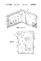
- FIG. 1 is a partial perspective view of a continuous business forms assembly with adjacent sheets separated along one marginal edge to illustrate a prior art forms construction
- FIG. 2 is a partial top view of a continuous business forms assembly in accordance with this invention.
- FIG. 3 is a partial perspective of a continuous business forms assembly, with adjacent sheets separated along one marginal edge to illustrate the forms construction in accordance with this invention.
- FIG. 4 is a cross-section of a forms construction in accordance with the present invention, taken along the line 4--4 of FIG. 2.
- FIGS. 1-3 a continuous business form assembly is shown at 10, with forms 12, 14, of the return-mailer-type extending longitudinally between transversely extending perforation lines 16.
- the forms 12, 14 are identical and, therefore, only one need be described in detail.
- the longitudinally extending perforation line 18 defines a removable marginal feed strip 20 provided with a line of feed holes 22. While no marginal feed strip is shown in association with the marginal edge 24, a second feed strip similar to strip 20 may be utilized if desired.
- transverse line of perforations 26, 28 and longitudinal lines of perforations 30 further define the form top sheet 32.
- a marginal strip 34, defined by line 30, may be removed by the recipient when it is desired to open the form.
- a transversely extending fold line 36 extends between perforation lines 18, 30 to divide the top sheet into, for example, a record portion to be retained by the user, and a separable remittance portion to be inserted in the return envelope.
- a window 38 is formed in the top sheet or cover 32.
- the return-mailer top sheet 32 has an inside surface 40 provided with an adhesive strip 42 which extends along the periphery of perforation lines 18, 26 and 28.
- the return mailer business form also includes a lower assembly on which the top sheet 32 is superposed.
- the lower assembly 44 may comprise two adhesively secured layers 44a and 44b forming a return envelope, which, in itself, is conventional and forms no part of this invention.
- the lower assembly 44 includes lines of perforations and feed holes which lie directly beneath a similar configuration on the top sheet 32.
- Reference numerals with prime designations denote lines, feed holes, etc. on the lower assembly 44 which lie directly underneath like elements on the top or cover sheet 32.
- FIGS. 2, 3 and 4 which represents the present invention, are substantially identical.
- the point of departure of the present invention involves the manner in which the window 38 in the top sheet 32 is ultimately covered.
- the window 38 is formed by a U-shaped cut which defines a flap 46 which is foldable about the fold line 36 between a first position where flap 46 closes the window 38, and a second position, illustrated in phantom in FIG. 1, where the flap is folded back against the sheet 40, thus opening the window 38.
- This arrangement is used so that during the manufacture of the form, the flap may be moved to its second position, permitting printed matter to be applied to the flap and to the inside surface 40 of the top sheet 32 in one printing step. Thereafter, the flap is closed, so that the printed matter thereon, such as an address, appears on the outside of the assembly.
- an oversized backing sheet 48 is adhesively secured to the flap to prevent the flap from moving through the window as it is closed.
- the backing sheet is sized to engage a peripheral line of adhesive 50 applied to surface 40 substantially adjacent three edges of the U-shaped cut defining window 38.
- this opening and closing process as it relates to window 38, flap 46 and backing sheet 48, slows down the form manufacturing process and causes numerous form failures.
- the present invention solves the prior art problems through the use of a patch or cover 52, the lower surface of which is provided with conventional, pressure sensitive adhesive by which the patch or cover may be temporarily applied to the upper or outer surface of adjacent sheet 44, at a location directly underneath the window 38.
- the patch in this case may be printed at the same time as sheet 44 which, in this exemplary embodiment, may constitute the front face of a return envelope assembly.
- Heat activated, dry adhesive is applied to the lower or interior surface 40 of the sheet 32 as at 54, in surrounding relationship to the window 38. It will be appreciated that, in the normally superposed relationship, the periphery of patch 52 will overlie the adhesive strip 54. This arrangement is best seen in FIG. 3 as well as in the section illustrated in FIG. 4.
- the patch 52 remains adhesively secured to sheet 44 until the final heat sealing step, at which time the releasable adhesive will yield to the greater strength of the heat activated glue, and will thereafter remain secured to the surface 40 of sheet 32, overlying the window 38.
Abstract
Description
Claims (11)
Priority Applications (3)
| Application Number | Priority Date | Filing Date | Title |
|---|---|---|---|
| US07/125,211 US4809906A (en) | 1987-11-25 | 1987-11-25 | Return mailer in place of flip window |
| EP88311072A EP0318261B1 (en) | 1987-11-25 | 1988-11-23 | Return mailer in place of flip window |
| BR888806175A BR8806175A (en) | 1987-11-25 | 1988-11-24 | RETURN POSTAL BAG SET, CONTINUOUS BUSINESS FORM SET, COMMERCIAL FORMS SET AND COMMERCIAL FORMS SETTING PROCESS |
Applications Claiming Priority (1)
| Application Number | Priority Date | Filing Date | Title |
|---|---|---|---|
| US07/125,211 US4809906A (en) | 1987-11-25 | 1987-11-25 | Return mailer in place of flip window |
Publications (1)
| Publication Number | Publication Date |
|---|---|
| US4809906A true US4809906A (en) | 1989-03-07 |
Family
ID=22418678
Family Applications (1)
| Application Number | Title | Priority Date | Filing Date |
|---|---|---|---|
| US07/125,211 Expired - Lifetime US4809906A (en) | 1987-11-25 | 1987-11-25 | Return mailer in place of flip window |
Country Status (3)
| Country | Link |
|---|---|
| US (1) | US4809906A (en) |
| EP (1) | EP0318261B1 (en) |
| BR (1) | BR8806175A (en) |
Cited By (12)
| Publication number | Priority date | Publication date | Assignee | Title |
|---|---|---|---|---|
| US4969594A (en) * | 1989-06-16 | 1990-11-13 | Moore Business Forms, Inc. | Business forms mailer and related manufacturing process |
| US5154344A (en) * | 1991-10-22 | 1992-10-13 | Mark Loch | Multiple part business form and related process |
| US5232147A (en) * | 1991-10-23 | 1993-08-03 | Belknap Business Forms, Inc. | Multi-component mailer and personalizing method |
| US5238182A (en) * | 1992-03-31 | 1993-08-24 | Moore Business Forms, Inc. | Four part form from two sheets |
| US5248082A (en) * | 1992-06-15 | 1993-09-28 | Bedinghaus Business Communications, Inc. | Two-way mailer with pull tab |
| US5360160A (en) * | 1993-07-01 | 1994-11-01 | Moore Business Forms, Inc. | Eccentric C-fold mailer with a plurality of reply envelopes |
| US6131802A (en) * | 1998-04-30 | 2000-10-17 | Lombardo; Leo | Pressure seal form |
| US6361078B1 (en) * | 1998-05-15 | 2002-03-26 | Moore U.S.A. Inc. | Multi-ply integrated label form |
| US6402022B1 (en) * | 1993-04-20 | 2002-06-11 | Laser Substrates, Inc | Mailing form for non-impact printing |
| US6435404B1 (en) | 2000-07-07 | 2002-08-20 | William Kurt Feick | Return mailer |
| US20040251299A1 (en) * | 2003-06-11 | 2004-12-16 | Moore John A. | Secure window mailer and method of making |
| US20110068161A1 (en) * | 2004-09-09 | 2011-03-24 | Dan Perrone | Two way electronic media mailer |
Families Citing this family (1)
| Publication number | Priority date | Publication date | Assignee | Title |
|---|---|---|---|---|
| DE4109859A1 (en) * | 1991-03-26 | 1992-10-01 | Guenter Baumann | LETTER FOR PROMOTIONAL PURPOSES |
Citations (9)
| Publication number | Priority date | Publication date | Assignee | Title |
|---|---|---|---|---|
| US1307421A (en) * | 1919-06-24 | schramm | ||
| US3273785A (en) * | 1965-03-25 | 1966-09-20 | Irving C Beckman | Self-mailer |
| US3380648A (en) * | 1967-03-24 | 1968-04-30 | Rose T. De Lyra | Reusable envelope |
| US3693869A (en) * | 1970-03-24 | 1972-09-26 | Robert F Eaves Jr | Remailable mailing envelope |
| US3837565A (en) * | 1972-02-15 | 1974-09-24 | E Johnsen | Rapid production envelope assemblies |
| US4598860A (en) * | 1983-10-05 | 1986-07-08 | Moore Business Forms, Inc. | Flip die cut label for folded mailer |
| US4706877A (en) * | 1987-01-09 | 1987-11-17 | Moore Business Forms, Inc. | Windowed mailer with return envelope for remittance document, having return mail-to address exposed by removal of original mail-to label |
| US4709850A (en) * | 1986-03-20 | 1987-12-01 | Moore Business Forms, Inc. | Mailer including return envelope and remittance stub combined in outer envelope |
| US4715530A (en) * | 1986-02-28 | 1987-12-29 | Moore Business Forms, Inc. | Two-part mailer with return envelope |
Family Cites Families (4)
| Publication number | Priority date | Publication date | Assignee | Title |
|---|---|---|---|---|
| US3411699A (en) * | 1966-06-24 | 1968-11-19 | Uarco Inc | Multiple use envelope assembly |
| FR2323612A1 (en) * | 1975-09-09 | 1977-04-08 | Herve Fils Papet Sentier | CONTINUOUS ASSEMBLY OF POSTAL CORRESPONDENCE ITEMS |
| US4055294A (en) * | 1975-12-11 | 1977-10-25 | Traise John E | Combined mailer and return envelope assembly |
| FR2491394B1 (en) * | 1980-10-02 | 1986-04-11 | Chambre Jean Paul | PROCESS FOR CONTINUOUS REALIZATION OF PERSONALIZED COMPUTER CARDS AND LETTER CARDS OBTAINED BY THIS PROCESS |
-
1987
- 1987-11-25 US US07/125,211 patent/US4809906A/en not_active Expired - Lifetime
-
1988
- 1988-11-23 EP EP88311072A patent/EP0318261B1/en not_active Expired
- 1988-11-24 BR BR888806175A patent/BR8806175A/en not_active Application Discontinuation
Patent Citations (9)
| Publication number | Priority date | Publication date | Assignee | Title |
|---|---|---|---|---|
| US1307421A (en) * | 1919-06-24 | schramm | ||
| US3273785A (en) * | 1965-03-25 | 1966-09-20 | Irving C Beckman | Self-mailer |
| US3380648A (en) * | 1967-03-24 | 1968-04-30 | Rose T. De Lyra | Reusable envelope |
| US3693869A (en) * | 1970-03-24 | 1972-09-26 | Robert F Eaves Jr | Remailable mailing envelope |
| US3837565A (en) * | 1972-02-15 | 1974-09-24 | E Johnsen | Rapid production envelope assemblies |
| US4598860A (en) * | 1983-10-05 | 1986-07-08 | Moore Business Forms, Inc. | Flip die cut label for folded mailer |
| US4715530A (en) * | 1986-02-28 | 1987-12-29 | Moore Business Forms, Inc. | Two-part mailer with return envelope |
| US4709850A (en) * | 1986-03-20 | 1987-12-01 | Moore Business Forms, Inc. | Mailer including return envelope and remittance stub combined in outer envelope |
| US4706877A (en) * | 1987-01-09 | 1987-11-17 | Moore Business Forms, Inc. | Windowed mailer with return envelope for remittance document, having return mail-to address exposed by removal of original mail-to label |
Cited By (14)
| Publication number | Priority date | Publication date | Assignee | Title |
|---|---|---|---|---|
| US4969594A (en) * | 1989-06-16 | 1990-11-13 | Moore Business Forms, Inc. | Business forms mailer and related manufacturing process |
| US5154344A (en) * | 1991-10-22 | 1992-10-13 | Mark Loch | Multiple part business form and related process |
| US5232147A (en) * | 1991-10-23 | 1993-08-03 | Belknap Business Forms, Inc. | Multi-component mailer and personalizing method |
| US5238182A (en) * | 1992-03-31 | 1993-08-24 | Moore Business Forms, Inc. | Four part form from two sheets |
| US5248082A (en) * | 1992-06-15 | 1993-09-28 | Bedinghaus Business Communications, Inc. | Two-way mailer with pull tab |
| US6402022B1 (en) * | 1993-04-20 | 2002-06-11 | Laser Substrates, Inc | Mailing form for non-impact printing |
| US5360160A (en) * | 1993-07-01 | 1994-11-01 | Moore Business Forms, Inc. | Eccentric C-fold mailer with a plurality of reply envelopes |
| US6131802A (en) * | 1998-04-30 | 2000-10-17 | Lombardo; Leo | Pressure seal form |
| US6361078B1 (en) * | 1998-05-15 | 2002-03-26 | Moore U.S.A. Inc. | Multi-ply integrated label form |
| US6435404B1 (en) | 2000-07-07 | 2002-08-20 | William Kurt Feick | Return mailer |
| US20040251299A1 (en) * | 2003-06-11 | 2004-12-16 | Moore John A. | Secure window mailer and method of making |
| US7073704B2 (en) * | 2003-06-11 | 2006-07-11 | The Standard Register Company | Secure window mailer and method of making |
| US20110068161A1 (en) * | 2004-09-09 | 2011-03-24 | Dan Perrone | Two way electronic media mailer |
| US8701978B2 (en) | 2004-09-09 | 2014-04-22 | R.R. Donnelley & Sons Company | Two way electronic media mailer |
Also Published As
| Publication number | Publication date |
|---|---|
| BR8806175A (en) | 1989-08-15 |
| EP0318261A3 (en) | 1990-01-10 |
| EP0318261B1 (en) | 1992-03-25 |
| EP0318261A2 (en) | 1989-05-31 |
Similar Documents
| Publication | Publication Date | Title |
|---|---|---|
| US3411699A (en) | Multiple use envelope assembly | |
| US5958174A (en) | Manufacture of telephone debit cards | |
| US4055294A (en) | Combined mailer and return envelope assembly | |
| US5427416A (en) | Business form | |
| US5129682A (en) | Business form with labels | |
| US4809906A (en) | Return mailer in place of flip window | |
| US4081127A (en) | Return envelope for mailer and method | |
| US5025978A (en) | Two-piece folder | |
| US4955640A (en) | Z-folded packing list/invoice | |
| US4632427A (en) | Combined mailer and return envelope | |
| US4981251A (en) | Mailer | |
| US5346123A (en) | Mailer type business form and intermediate with built in reply envelope | |
| MXPA96005101A (en) | Postal piece of seal by pressure folded e | |
| US5060847A (en) | Film processing envelope with optional removable negative pouch | |
| US5062570A (en) | Mailer with die cut insert and self-imaging area | |
| US5039000A (en) | Mailer with tear strip on outgoing and return envelopes | |
| US5163612A (en) | Method of making a mailer with tear strip on outgoing and return envelopes | |
| US5360160A (en) | Eccentric C-fold mailer with a plurality of reply envelopes | |
| EP0528576B1 (en) | Mailers and business form assemblies for producing mailers | |
| US4023727A (en) | Mailing envelope structure and method | |
| US4911354A (en) | Business form incorporating flip window with clear film patch | |
| AU616867B2 (en) | Envelopes | |
| JPH0312552Y2 (en) | ||
| US5238183A (en) | Bifold mailer with return envelope | |
| US5154344A (en) | Multiple part business form and related process |
Legal Events
| Date | Code | Title | Description |
|---|---|---|---|
| AS | Assignment |
Owner name: MOORE BUSINESS FORMS, INC., 300 LONG BOULEVARD, GR Free format text: ASSIGNMENT OF ASSIGNORS INTEREST.;ASSIGNOR:LOMBARDO, LEO;REEL/FRAME:004814/0580 Effective date: 19871117 |
|
| STCF | Information on status: patent grant |
Free format text: PATENTED CASE |
|
| FPAY | Fee payment |
Year of fee payment: 4 |
|
| FPAY | Fee payment |
Year of fee payment: 8 |
|
| FEPP | Fee payment procedure |
Free format text: PAYOR NUMBER ASSIGNED (ORIGINAL EVENT CODE: ASPN); ENTITY STATUS OF PATENT OWNER: LARGE ENTITY |
|
| FPAY | Fee payment |
Year of fee payment: 12 |
|
| AS | Assignment |
Owner name: MOORE NORTH AMERICA, INC., CANADA Free format text: CHANGE OF NAME;ASSIGNOR:MOORE U.S.A. INC.;REEL/FRAME:014090/0607 Effective date: 19980915 Owner name: MOORE U.S.A. INC., CANADA Free format text: CHANGE OF NAME;ASSIGNOR:MOORE BUSINESS FORMS, INC.;REEL/FRAME:014097/0159 Effective date: 19961104 |
|
| AS | Assignment |
Owner name: CITICORP NORTH AMERICA, INC., NEW YORK Free format text: SECURITY AGREEMENT;ASSIGNOR:MOORE NORTH AMERICA, INC.;REEL/FRAME:014108/0136 Effective date: 20030515 |
|
| FEPP | Fee payment procedure |
Free format text: PAYER NUMBER DE-ASSIGNED (ORIGINAL EVENT CODE: RMPN); ENTITY STATUS OF PATENT OWNER: LARGE ENTITY Free format text: PAYOR NUMBER ASSIGNED (ORIGINAL EVENT CODE: ASPN); ENTITY STATUS OF PATENT OWNER: LARGE ENTITY |