US4813725A - Concealed check rail lock and keeper - Google Patents
Concealed check rail lock and keeper Download PDFInfo
- Publication number
- US4813725A US4813725A US07/198,672 US19867288A US4813725A US 4813725 A US4813725 A US 4813725A US 19867288 A US19867288 A US 19867288A US 4813725 A US4813725 A US 4813725A
- Authority
- US
- United States
- Prior art keywords
- check rail
- housing
- check
- shaft
- face
- Prior art date
- Legal status (The legal status is an assumption and is not a legal conclusion. Google has not performed a legal analysis and makes no representation as to the accuracy of the status listed.)
- Expired - Lifetime
Links
Images
Classifications
-
- E—FIXED CONSTRUCTIONS
- E05—LOCKS; KEYS; WINDOW OR DOOR FITTINGS; SAFES
- E05C—BOLTS OR FASTENING DEVICES FOR WINGS, SPECIALLY FOR DOORS OR WINDOWS
- E05C3/00—Fastening devices with bolts moving pivotally or rotatively
- E05C3/02—Fastening devices with bolts moving pivotally or rotatively without latching action
- E05C3/04—Fastening devices with bolts moving pivotally or rotatively without latching action with operating handle or equivalent member rigid with the bolt
- E05C3/041—Fastening devices with bolts moving pivotally or rotatively without latching action with operating handle or equivalent member rigid with the bolt rotating about an axis perpendicular to the surface on which the fastener is mounted
-
- Y—GENERAL TAGGING OF NEW TECHNOLOGICAL DEVELOPMENTS; GENERAL TAGGING OF CROSS-SECTIONAL TECHNOLOGIES SPANNING OVER SEVERAL SECTIONS OF THE IPC; TECHNICAL SUBJECTS COVERED BY FORMER USPC CROSS-REFERENCE ART COLLECTIONS [XRACs] AND DIGESTS
- Y10—TECHNICAL SUBJECTS COVERED BY FORMER USPC
- Y10S—TECHNICAL SUBJECTS COVERED BY FORMER USPC CROSS-REFERENCE ART COLLECTIONS [XRACs] AND DIGESTS
- Y10S292/00—Closure fasteners
- Y10S292/53—Mounting and attachment
-
- Y—GENERAL TAGGING OF NEW TECHNOLOGICAL DEVELOPMENTS; GENERAL TAGGING OF CROSS-SECTIONAL TECHNOLOGIES SPANNING OVER SEVERAL SECTIONS OF THE IPC; TECHNICAL SUBJECTS COVERED BY FORMER USPC CROSS-REFERENCE ART COLLECTIONS [XRACs] AND DIGESTS
- Y10—TECHNICAL SUBJECTS COVERED BY FORMER USPC
- Y10T—TECHNICAL SUBJECTS COVERED BY FORMER US CLASSIFICATION
- Y10T292/00—Closure fasteners
- Y10T292/08—Bolts
- Y10T292/1039—Swinging and camming
- Y10T292/1041—Rigid operating means
Definitions
- This invention pertains to a check rail lock and keeper which except for the operating handle can be completely concealed within the check rails of the upper and lower sash of a double hung window.
- Each of the check rails is provided with a cavity with the cavity in the check rail of the lower sash receiving and enclosing a check rail lock housing having an exposed face and which rotatably mounts a locking cam operable by a rotatable shaft extending upwardly from the housing and having a handle at a level above the check rail associated with the rotatable shaft.
- a keeper is positioned in and enclosed in a cavity in the check rail of the upper sash at a location to permit the mounting of weather stripping and has downwardly inclined openings extending from the front face thereof enabling the insertion of fastening members into the check rail without interfering with window glazing.
- the concealed check rail lock has a number of components known in prior art structures and particularly as shown in my copending application Ser. No. 821,004 filed Jan. 22, 1986 now U.S. Pat. No. 4,736,972 granted Apr. 12, 1988.
- the prior check rail lock has a housing mountable to the top of a check rail and which mounts a rotatable shaft having a locking cam disposed internally of the housing and a handle secured to the shaft externally of the housing.
- a locking cam is rotatable between locked and unlocked positions as determined by limit stops within the housing and a spring detent washer detents the locking cam in either of these positions.
- a coacting keeper interengages with the locking cam in a locked position.
- a primary feature of the invention is to provide a new and improved concealed check rail lock and keeper having components insertable in cavities in the check rails of the upper and lower sash of a double hung window with one component being a housing having a rotatable locking cam disposed internally thereof and with a rotatable shaft mounting the locking cam and having only a handle secured to the shaft which is exposed to view.
- Another component is a keeper which is mountable in a cavity in the check rail of the upper sash with only an exposed front face and with downwardly inclined openings for receiving fasteners which can extend downwardly into the upper sash check rail without interference with window glazing.
- the keeper can be at the level of the lower edge of the window glazing while still being located at a distance from the lower edge of the upper sash check rail to permit the mounting of weather stripping.
- the concealed check rail lock has a housing with a rotatable shaft extending upwardly therefrom and a locking cam within the housing secured to the shaft.
- a handle is secured to the upper end of the shaft at a distance from the housing.
- the housing can be mounted in a cavity of the check rail of the lower sash of a double hung window and have an exposed face.
- the check rail has a notch above the cavity to permit assembly with the part of the shaft above the housing positioned in the notch and a raised section of the housing fits within the remainder of the notch to coact with the upper surface of the check rail to form a smooth continuous surface.
- the keeper fits within a cavity in the check rail of the upper sash of the double hung window to have only an exposed face.
- the keeper is at the level of the lower part of the window glazing and above the lower edge of the check rail to permit mounting of weather stripping material.
- the keeper has at least a pair of openings extending to the face of the keeper which are downwardly inclined to permit the insertion of fasteners into the check rail without interfering with the glazing.
- the handle has a generally frusto-conical section at the upper end of the shaft and with an offset which overlies the notch and a portion of the check rail of the upper sash when the handle is in locked position and which moves to a position out of overlapped relation with the upper sash check rail when the lock is in an opened position.
- An object of the invention is to provide a new and improved concealed check rail lock and keeper having a housing and a keeper which can both be enclosed within cavities formed in the check rails of the sash of a double hung window with only an operating handle exposed.
- Still another object of the invention is to provide a concealed check rail lock and keeper as defined in the preceding paragraph wherein both the housing and keeper are constructed to provide a neat and pleasing appearance for a window and with the structural features of the keeper enabling mounting thereof in a position to enable the use of weather stripping between the check rails and fastener members which can secure the keeper to the check rail of the upper sash without interference from the window glazing.
- Still another object of the invention is to provide a concealed check rail lock for mounting on a double hung window having upper and lower sash with check rails in alignment when the window is closed comprising, a housing with a top wall and an interior space and having a raised section, a shaft rotatably mounted in said housing and extending outwardly thereof to the rear of the raised section, a locking cam in said housing fixed to said shaft, and a handle fixed to an end of the shaft at a distance from the top wall and overlying said raised section whereby said housing can fit within a cavity formed in the check rail of the lower sash and a notch formed in said last mentioned check rail above said cavity receives said raised section to have only said handle above the surface of the lower sash check rail.
- a further object of the invention is to provide a concealed check rail lock and keeper having a housing with a locking cam mountable in a cavity of the check rail of the lower sash of a double hung window and a keeper mountable in a cavity of the check rail of the upper sash of such a window and at the level of glazing in said upper sash, said keeper having a face flush with a face of the upper sash check rail, and means defining a pair of fastener receiving openings at said face of the keeper which extend downwardly at an angle to receive fastening members which avoid contact with the glazing.
- a further object of the invention is to provide a concealed cam lock and keeper comprising, in combination, a housing having a rotatable locking cam and a keeper for engagement by said locking cam, the improvement wherein both said housing and keeper may be hidden from view by mounting in cavities formed in the adjacent check rails of upper and lower sash of a window, said housing having a top wall, a rotatable shaft extending through said top wall and secured to said locking cam within the housing, a handle fixed to said shaft at a distance from said top wall, a raised section of said housing extending between a front face of the housing and said shaft, and said keeper having a pair of downwardly inclined fastener openings at a front face thereof whereby fasteners may extend through said openings into the check rail.
- Still another object of the invention is to provide a concealed cam lock as defined in the preceding paragraph wherein the handle has a generally frusto-conical shape surrounding said shaft and which has an offset extending beyond the face of the housing when the handle is in a locked position.
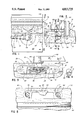
- FIG. 1 is a plan view of the concealed check rail lock shown in association with the sash check rails of a double hung window;
- FIG. 2 is a vertical sectional view taken generally along the line 2--2 in FIG. 1;
- FIG. 3 is a vertical section taken generally along the line 3--3 in FIG. 2;
- FIG. 4 is a sectional view taken along the line 4--4 in FIG. 3;
- FIG. 5 is a vertical view taken along the line 5--5 in FIG. 2.
- the concealed check rail lock is indicated generally at 10 and the concealed keeper is indicated generally at 11. These components are mountable in the check rails of upper and lower sash of a double hung window.
- the check rail 15 of the lower sash has a cavity 16 to receive a housing 20 of the check rail lock and with the housing 20 being concealed by an upper part 22 of the check rail.
- the housing 20 has a front face 24 generally flush with an exposed vertical face 26 of the check rail 15 with lateral extensions 28 and 30 each having an opening to receive a fastening member in the form of attaching screws 31 and 32, respectively, which thread into the check rail.
- the housing has an internal chamber 36 opening to the front face 24 thereof with a rotatable locking cam 38 being mounted in this chamber and being fixed to a shaft 40 rotatably mounted in the housing and extending upwardly therefrom as seen particularly in FIG. 2.
- the shaft has a handle 42 formed integrally therewith or separate therefrom but fixed thereto with a generally frusto-conical section 44 spaced from a top wall 46 of the housing 20 and lying immediately above the top surface of the check rail 15.
- the cavity 16 is formed in the check rail and also a notch is cut inwardly from the front face 26 of the check rail through the top portion 22 thereof to permit passage of the exposed part of the shaft 40 to the position shown in FIG. 2.
- a raised section 50 of the housing extends above the housing top wall 46 and between the exposed part of the shaft 40 and the housing front face 24 to fill the notch 48 and form a continuous upper surface for the check rail 15.
- a rotatable locking cam 38 is rotatable between locked and unlocked positions by rotation of the handle 42 between a locked position shown in the drawings and an unlocked position wherein the handle is rotated through approximately 180° in a counterclockwise direction as viewed in FIG. 1.
- the limits of rotation of the rotary locking cam are controlled by an abutting relation between structure on the housing and the rotatable locking cam and the locking cam can be held in either position by means of a spring washer 60 keyed to the rotatable shaft 40 and having one or more detents 61 which coacts with a detent cavity 62 formed on the housing 20.
- the frusto-conical handle section 44 has an offset part 64 which overlies the raised section 50 of the housing and part of the check rail of the upper sash when the handle 42 is in locked position.
- the keeper 11 is mounted in a cavity 70 of a check rail 72 of the upper sash and with the upper sash having glazing indicated generally at 74 with the lower part thereof embedded in mounting material 76 positioned within a cavity 78 of the check rail.
- the keeper 11 has a face 80 which is mountable generally flush with a vertical face 81 of the check rail 72 and has a depth dimension approximately equal to the depth of the cavity 70 formed in the check rail.
- the keeper has a downward projection 84 for coaction with the rotatable locking cam 38 of the check rail lock when the handle 42 is in locked position.
- a decorative window strip 85 can overlie and extend upwardly from the keeper 11.
- the keeper 11 is mounted in the check rail 72 sufficiently high as to permit mounting of weather stripping 86 and as a consequence is mounted generally at the level of the cavity 78 which receives the lower edge of the window glazing 74.
- the keeper is provided with a pair of downwardly inclined openings 90 and 92 extending from the face 80 which enable fasteners in the form of screws 93 and 94 to extend at a downward angle to thread into the check rail 72 and without interference with the glazing 74.
- the concealed cam lock and keeper positioned in association with the check rails 15 and 72 as seen in the drawings, all of the components except for the handle 42 are concealed.
- the components are mounted to enable the use of weather stripping coacting between the check rails and the keeper can be attached without interference with the glazing of the upper sash.
- the handle can be provided with the directional arrow and the term "LOCK" in order to indicate the handle location when the rotatable locking cam 38 is positioned for coaction with the projection 84 of the keeper to lock the window.
Abstract
Description
Claims (8)
Priority Applications (1)
| Application Number | Priority Date | Filing Date | Title |
|---|---|---|---|
| US07/198,672 US4813725A (en) | 1986-11-12 | 1988-05-24 | Concealed check rail lock and keeper |
Applications Claiming Priority (2)
| Application Number | Priority Date | Filing Date | Title |
|---|---|---|---|
| US92948686A | 1986-11-21 | 1986-11-21 | |
| US07/198,672 US4813725A (en) | 1986-11-12 | 1988-05-24 | Concealed check rail lock and keeper |
Related Parent Applications (1)
| Application Number | Title | Priority Date | Filing Date |
|---|---|---|---|
| US92948686A Continuation | 1986-11-12 | 1986-11-21 |
Publications (1)
| Publication Number | Publication Date |
|---|---|
| US4813725A true US4813725A (en) | 1989-03-21 |
Family
ID=26894029
Family Applications (1)
| Application Number | Title | Priority Date | Filing Date |
|---|---|---|---|
| US07/198,672 Expired - Lifetime US4813725A (en) | 1986-11-12 | 1988-05-24 | Concealed check rail lock and keeper |
Country Status (1)
| Country | Link |
|---|---|
| US (1) | US4813725A (en) |
Cited By (39)
| Publication number | Priority date | Publication date | Assignee | Title |
|---|---|---|---|---|
| US5161839A (en) * | 1991-07-25 | 1992-11-10 | Truth Division Of Spx Corporation | Check rail lock and method of making check rail lock paintable after assembly |
| US5219193A (en) * | 1992-05-22 | 1993-06-15 | Truth Division Of Spx Corporation | Forced entry resistant check rail lock |
| US5437173A (en) * | 1993-02-18 | 1995-08-01 | Truth Division Of Spx Corporation | Window lock with indicator |
| US5448857A (en) * | 1994-03-25 | 1995-09-12 | Truth Hardware Corporation | Locking system for a double hung window |
| US5582442A (en) * | 1995-09-15 | 1996-12-10 | Truth Hardware Corporation | Latch assembly and manufacturing and painting processes |
| US5813710A (en) * | 1997-04-08 | 1998-09-29 | Truth Hardware Corporation | Flush lock actuator |
| US6142541A (en) * | 1998-11-24 | 2000-11-07 | Truth Hardware Corporation | Pick resistant sash lock |
| US6364375B1 (en) | 2000-02-15 | 2002-04-02 | Ashland Products, Inc. | Apparatus for securing sash window |
| US6484444B1 (en) | 2000-11-14 | 2002-11-26 | Ashland Products, Inc. | Stop for a slidable window |
| US6767038B1 (en) | 2001-02-08 | 2004-07-27 | G-U Hardware, Inc. | Multi-point casement handle |
| US20040217600A1 (en) * | 2003-02-28 | 2004-11-04 | Kevin Argo | Latch assembly for sliding door |
| US20040221513A1 (en) * | 2003-05-06 | 2004-11-11 | Dean Pettit | Forced entry resistance device for sash window assembly |
| US6854214B2 (en) | 2000-11-14 | 2005-02-15 | Ashland Products, Inc. | Stop for a slidable window |
| US20050146143A1 (en) * | 2004-01-06 | 2005-07-07 | Lutfallah Anthony G. | Universal stop for a slidable window |
| US6962024B1 (en) * | 2001-07-18 | 2005-11-08 | Hughes Supply Company Of Thomasville, Inc. | Locking window having a sweep latch |
| US6983963B2 (en) | 2002-01-29 | 2006-01-10 | Newell Operating Company | Forced entry resistance device for sash lock |
| US7063361B1 (en) | 2002-05-30 | 2006-06-20 | Barry Gene Lawrence | Locking window |
| US20070085350A1 (en) * | 2005-10-19 | 2007-04-19 | Luke Liang | Sash lock with condition signal |
| US7510221B2 (en) | 2006-02-09 | 2009-03-31 | Newell Operating Company | Sash lock assembly having forced entry resistance |
| US8205919B2 (en) | 2008-04-28 | 2012-06-26 | Newell Operating Company | Sash lock with forced entry resistance |
| US8205920B2 (en) | 2008-04-28 | 2012-06-26 | Newell Operating Company | Sash lock with forced entry resistance |
| US20140165884A1 (en) * | 2012-12-17 | 2014-06-19 | Tadhg James O'Gara | WorknStand |
| US9388608B2 (en) | 2012-07-31 | 2016-07-12 | Simonton Building Products Llc | Window locking arrangements |
| US9840860B2 (en) | 2009-05-29 | 2017-12-12 | Vision Industries Group, Inc. | Double-action, adjustable, after-market sash stop |
| US10006232B2 (en) | 2006-03-28 | 2018-06-26 | Vision Industries Group | Window vent stop with flexible side engagement pieces |
| US10107021B1 (en) | 2006-03-28 | 2018-10-23 | Vision Industries Group, Inc. | Window vent stop with plastic spring member for bi-directional biasing of the tumbler |
| US10119310B2 (en) | 2014-03-06 | 2018-11-06 | Vision Industries Group, Inc. | Combination sash lock and tilt latch with improved interconnection for blind mating of the latch to the lock |
| US10633897B2 (en) | 2017-02-16 | 2020-04-28 | Vision Industries Group, Inc. | Tamper-resistant lock |
| US10704297B2 (en) | 2014-03-06 | 2020-07-07 | Vision Industries, Inc. | Impact resistant lock and tilt latch combination for a sliding sash window |
| US10844636B2 (en) | 2017-05-23 | 2020-11-24 | Vision Industries Group, Inc. | Combination forced entry resistant sash lock and tilt latch, also functioning as a window opening control device |
| US10844642B2 (en) | 2014-03-06 | 2020-11-24 | Vision Industries Group, Inc. | Combination four-position sash lock and tilt latch also functioning as a window opening control device |
| US10865592B2 (en) | 2014-03-06 | 2020-12-15 | Vision Industries Group, Inc. | Sash lock and tilt latch also functioning as a window vent stop, with automatic locking upon closure |
| US11047157B1 (en) | 2006-03-28 | 2021-06-29 | Vision Industries Group, Inc. | Vent stop |
| USD927957S1 (en) | 2018-04-03 | 2021-08-17 | John D. King | Recessed sash lock for a double-hung window |
| US11118376B1 (en) | 2017-10-18 | 2021-09-14 | Vision Industries Group, Inc. | Combination sash lock and tilt latch and slidable window vent stop |
| US11168492B1 (en) | 2017-02-16 | 2021-11-09 | Vision Industries Group, Inc. | Tamper resistant sash lock |
| US11168495B1 (en) | 2018-08-01 | 2021-11-09 | Vision Industries Group, Inc. | Automatically resetting window vent stop with dual safety features |
| US11187010B1 (en) | 2019-09-19 | 2021-11-30 | Vision Industries, Inc. | Forced-entry-resistant sash lock |
| US11220845B2 (en) | 2015-06-08 | 2022-01-11 | Andersen Corporation | Powered sash lock and control systems therefor |
Citations (24)
| Publication number | Priority date | Publication date | Assignee | Title |
|---|---|---|---|---|
| US190341A (en) * | 1877-05-01 | Improvement in lock-cases | ||
| US404916A (en) * | 1889-06-11 | Fastener for the meeting-rails of sashes | ||
| US423761A (en) * | 1890-03-18 | Fastener for the meeting-rails of sashes | ||
| US550873A (en) * | 1895-12-03 | Window-fastener | ||
| US584343A (en) * | 1897-06-15 | Sash-fastener | ||
| US797768A (en) * | 1904-08-18 | 1905-08-22 | George L Fisher | Casement-fastener. |
| US897623A (en) * | 1906-11-12 | 1908-09-01 | Abiel Gifford Howland | Window-fastener. |
| US946172A (en) * | 1909-06-22 | 1910-01-11 | Charles E Tayntor | Sash-fastener. |
| US1071509A (en) * | 1913-03-25 | 1913-08-26 | Cornelius F Courson | Latch device for windows, &c. |
| US1144289A (en) * | 1914-10-16 | 1915-06-22 | John C Blair | Sash-fastener. |
| US1230021A (en) * | 1915-01-18 | 1917-06-12 | Charles J Pembroke | Fastening device. |
| US1560654A (en) * | 1923-06-28 | 1925-11-10 | Martin H Brede | Closure cap and lock for filler necks and the like |
| US1799480A (en) * | 1929-09-13 | 1931-04-07 | Henrietta Payton | Burglarproof lock for window sashes |
| CH150564A (en) * | 1931-04-04 | 1931-11-15 | R Loewengart Fa | Eccentric lock with engagement edge perpendicular to the eccentric disc. |
| US1900936A (en) * | 1929-11-01 | 1933-03-14 | Alexander J Gibson | Window fastener |
| US1948542A (en) * | 1932-03-28 | 1934-02-27 | Nat Ventilating Window Lock Co | Sash lock |
| US2135105A (en) * | 1937-05-12 | 1938-11-01 | Harry A Knauff | Latch |
| US2258617A (en) * | 1939-10-21 | 1941-10-14 | Harry A Knauff | Latching device |
| US2581816A (en) * | 1948-08-17 | 1952-01-08 | Simmons Fastener Corp | Fastener for butt joints |
| US2855236A (en) * | 1957-04-09 | 1958-10-07 | Harry A Knauff | Latching device |
| US3078704A (en) * | 1959-06-24 | 1963-02-26 | Rifkin Michael | Window latching device |
| US3347580A (en) * | 1965-10-21 | 1967-10-17 | Whiting Mfg Inc T | Latch for securing a truck door |
| DE2140313A1 (en) * | 1970-08-11 | 1972-04-13 | Interlocking Systems International Ltd., Nassau (Bahamas) | Ratchet locking device |
| US4293154A (en) * | 1979-09-28 | 1981-10-06 | Cassells Melvin K | Safety lock for window sashes and the like |
-
1988
- 1988-05-24 US US07/198,672 patent/US4813725A/en not_active Expired - Lifetime
Patent Citations (24)
| Publication number | Priority date | Publication date | Assignee | Title |
|---|---|---|---|---|
| US190341A (en) * | 1877-05-01 | Improvement in lock-cases | ||
| US404916A (en) * | 1889-06-11 | Fastener for the meeting-rails of sashes | ||
| US423761A (en) * | 1890-03-18 | Fastener for the meeting-rails of sashes | ||
| US550873A (en) * | 1895-12-03 | Window-fastener | ||
| US584343A (en) * | 1897-06-15 | Sash-fastener | ||
| US797768A (en) * | 1904-08-18 | 1905-08-22 | George L Fisher | Casement-fastener. |
| US897623A (en) * | 1906-11-12 | 1908-09-01 | Abiel Gifford Howland | Window-fastener. |
| US946172A (en) * | 1909-06-22 | 1910-01-11 | Charles E Tayntor | Sash-fastener. |
| US1071509A (en) * | 1913-03-25 | 1913-08-26 | Cornelius F Courson | Latch device for windows, &c. |
| US1144289A (en) * | 1914-10-16 | 1915-06-22 | John C Blair | Sash-fastener. |
| US1230021A (en) * | 1915-01-18 | 1917-06-12 | Charles J Pembroke | Fastening device. |
| US1560654A (en) * | 1923-06-28 | 1925-11-10 | Martin H Brede | Closure cap and lock for filler necks and the like |
| US1799480A (en) * | 1929-09-13 | 1931-04-07 | Henrietta Payton | Burglarproof lock for window sashes |
| US1900936A (en) * | 1929-11-01 | 1933-03-14 | Alexander J Gibson | Window fastener |
| CH150564A (en) * | 1931-04-04 | 1931-11-15 | R Loewengart Fa | Eccentric lock with engagement edge perpendicular to the eccentric disc. |
| US1948542A (en) * | 1932-03-28 | 1934-02-27 | Nat Ventilating Window Lock Co | Sash lock |
| US2135105A (en) * | 1937-05-12 | 1938-11-01 | Harry A Knauff | Latch |
| US2258617A (en) * | 1939-10-21 | 1941-10-14 | Harry A Knauff | Latching device |
| US2581816A (en) * | 1948-08-17 | 1952-01-08 | Simmons Fastener Corp | Fastener for butt joints |
| US2855236A (en) * | 1957-04-09 | 1958-10-07 | Harry A Knauff | Latching device |
| US3078704A (en) * | 1959-06-24 | 1963-02-26 | Rifkin Michael | Window latching device |
| US3347580A (en) * | 1965-10-21 | 1967-10-17 | Whiting Mfg Inc T | Latch for securing a truck door |
| DE2140313A1 (en) * | 1970-08-11 | 1972-04-13 | Interlocking Systems International Ltd., Nassau (Bahamas) | Ratchet locking device |
| US4293154A (en) * | 1979-09-28 | 1981-10-06 | Cassells Melvin K | Safety lock for window sashes and the like |
Cited By (45)
| Publication number | Priority date | Publication date | Assignee | Title |
|---|---|---|---|---|
| US5161839A (en) * | 1991-07-25 | 1992-11-10 | Truth Division Of Spx Corporation | Check rail lock and method of making check rail lock paintable after assembly |
| US5219193A (en) * | 1992-05-22 | 1993-06-15 | Truth Division Of Spx Corporation | Forced entry resistant check rail lock |
| US5437173A (en) * | 1993-02-18 | 1995-08-01 | Truth Division Of Spx Corporation | Window lock with indicator |
| US5448857A (en) * | 1994-03-25 | 1995-09-12 | Truth Hardware Corporation | Locking system for a double hung window |
| US5582442A (en) * | 1995-09-15 | 1996-12-10 | Truth Hardware Corporation | Latch assembly and manufacturing and painting processes |
| US5813710A (en) * | 1997-04-08 | 1998-09-29 | Truth Hardware Corporation | Flush lock actuator |
| US6142541A (en) * | 1998-11-24 | 2000-11-07 | Truth Hardware Corporation | Pick resistant sash lock |
| US6364375B1 (en) | 2000-02-15 | 2002-04-02 | Ashland Products, Inc. | Apparatus for securing sash window |
| US6572158B2 (en) | 2000-02-15 | 2003-06-03 | Ashland Products, Inc. | Apparatus for securing sash window |
| US6484444B1 (en) | 2000-11-14 | 2002-11-26 | Ashland Products, Inc. | Stop for a slidable window |
| US6854214B2 (en) | 2000-11-14 | 2005-02-15 | Ashland Products, Inc. | Stop for a slidable window |
| US6767038B1 (en) | 2001-02-08 | 2004-07-27 | G-U Hardware, Inc. | Multi-point casement handle |
| US6962024B1 (en) * | 2001-07-18 | 2005-11-08 | Hughes Supply Company Of Thomasville, Inc. | Locking window having a sweep latch |
| US6983963B2 (en) | 2002-01-29 | 2006-01-10 | Newell Operating Company | Forced entry resistance device for sash lock |
| US7063361B1 (en) | 2002-05-30 | 2006-06-20 | Barry Gene Lawrence | Locking window |
| US20040217600A1 (en) * | 2003-02-28 | 2004-11-04 | Kevin Argo | Latch assembly for sliding door |
| US6925758B2 (en) | 2003-05-06 | 2005-08-09 | Newell Operating Company | Forced entry resistance device for sash window assembly |
| US20040221513A1 (en) * | 2003-05-06 | 2004-11-11 | Dean Pettit | Forced entry resistance device for sash window assembly |
| US20050146143A1 (en) * | 2004-01-06 | 2005-07-07 | Lutfallah Anthony G. | Universal stop for a slidable window |
| US20070085350A1 (en) * | 2005-10-19 | 2007-04-19 | Luke Liang | Sash lock with condition signal |
| US7699365B2 (en) * | 2005-10-19 | 2010-04-20 | Vision Industries Group, Inc. | Sash lock with condition signal |
| US7510221B2 (en) | 2006-02-09 | 2009-03-31 | Newell Operating Company | Sash lock assembly having forced entry resistance |
| US10006232B2 (en) | 2006-03-28 | 2018-06-26 | Vision Industries Group | Window vent stop with flexible side engagement pieces |
| US11047157B1 (en) | 2006-03-28 | 2021-06-29 | Vision Industries Group, Inc. | Vent stop |
| US10107021B1 (en) | 2006-03-28 | 2018-10-23 | Vision Industries Group, Inc. | Window vent stop with plastic spring member for bi-directional biasing of the tumbler |
| US10053896B2 (en) | 2006-03-28 | 2018-08-21 | Vision Industries Group, Inc. | Window vent stop with flexible side engagement pieces |
| US8205919B2 (en) | 2008-04-28 | 2012-06-26 | Newell Operating Company | Sash lock with forced entry resistance |
| US8205920B2 (en) | 2008-04-28 | 2012-06-26 | Newell Operating Company | Sash lock with forced entry resistance |
| US9840860B2 (en) | 2009-05-29 | 2017-12-12 | Vision Industries Group, Inc. | Double-action, adjustable, after-market sash stop |
| US10920469B2 (en) | 2009-05-29 | 2021-02-16 | Vision Industries Group, Inc | Double-action, adjustable, after-market sash stop |
| US9388608B2 (en) | 2012-07-31 | 2016-07-12 | Simonton Building Products Llc | Window locking arrangements |
| US20140165884A1 (en) * | 2012-12-17 | 2014-06-19 | Tadhg James O'Gara | WorknStand |
| US10844642B2 (en) | 2014-03-06 | 2020-11-24 | Vision Industries Group, Inc. | Combination four-position sash lock and tilt latch also functioning as a window opening control device |
| US10704297B2 (en) | 2014-03-06 | 2020-07-07 | Vision Industries, Inc. | Impact resistant lock and tilt latch combination for a sliding sash window |
| US10865592B2 (en) | 2014-03-06 | 2020-12-15 | Vision Industries Group, Inc. | Sash lock and tilt latch also functioning as a window vent stop, with automatic locking upon closure |
| US10323446B2 (en) | 2014-03-06 | 2019-06-18 | Vision Industries Group, Inc. | Integrated sash lock and tilt latch combination with improved interconnection capability therebetween |
| US10119310B2 (en) | 2014-03-06 | 2018-11-06 | Vision Industries Group, Inc. | Combination sash lock and tilt latch with improved interconnection for blind mating of the latch to the lock |
| US11220845B2 (en) | 2015-06-08 | 2022-01-11 | Andersen Corporation | Powered sash lock and control systems therefor |
| US10633897B2 (en) | 2017-02-16 | 2020-04-28 | Vision Industries Group, Inc. | Tamper-resistant lock |
| US11168492B1 (en) | 2017-02-16 | 2021-11-09 | Vision Industries Group, Inc. | Tamper resistant sash lock |
| US10844636B2 (en) | 2017-05-23 | 2020-11-24 | Vision Industries Group, Inc. | Combination forced entry resistant sash lock and tilt latch, also functioning as a window opening control device |
| US11118376B1 (en) | 2017-10-18 | 2021-09-14 | Vision Industries Group, Inc. | Combination sash lock and tilt latch and slidable window vent stop |
| USD927957S1 (en) | 2018-04-03 | 2021-08-17 | John D. King | Recessed sash lock for a double-hung window |
| US11168495B1 (en) | 2018-08-01 | 2021-11-09 | Vision Industries Group, Inc. | Automatically resetting window vent stop with dual safety features |
| US11187010B1 (en) | 2019-09-19 | 2021-11-30 | Vision Industries, Inc. | Forced-entry-resistant sash lock |
Similar Documents
| Publication | Publication Date | Title |
|---|---|---|
| US4813725A (en) | Concealed check rail lock and keeper | |
| US5741032A (en) | Sash lock | |
| US4105235A (en) | Lock keeper | |
| US20030057717A1 (en) | Sash lock for a sash window | |
| US3967845A (en) | Reinforced striker assembly for door locks | |
| US4183568A (en) | Lock guard | |
| US3241873A (en) | Snap-on strike box | |
| US4635976A (en) | Sliding window lock | |
| US5489131A (en) | Locking handle for window | |
| US4530531A (en) | Device for securing sliding closures | |
| US2695808A (en) | Adjustable strike plate | |
| US5369969A (en) | Door handle with lock housing | |
| EP0969178A1 (en) | A window with a ventilation cover and a burglary preventing member | |
| US4436331A (en) | Multiple-position hasp-type door check | |
| US1576506A (en) | Door casing | |
| JP2905174B2 (en) | Microwave oven swing prevention structure | |
| CA1281052C (en) | Concealed check rail lock and keeper | |
| JPS5934699Y2 (en) | door lock strike device | |
| GB2310449A (en) | Lockable turnbuckle blocking device | |
| JP3132255B2 (en) | Door outside handle structure | |
| JP2601988Y2 (en) | Lock receiving device | |
| GB2483468A (en) | Hinge with hinge pin positioned at a distance from the mounting surface | |
| JP3161969B2 (en) | Double door structure | |
| JPH0629391Y2 (en) | Handle pedestal | |
| AU2005211522B2 (en) | Door guard |
Legal Events
| Date | Code | Title | Description |
|---|---|---|---|
| FEPP | Fee payment procedure |
Free format text: PAYOR NUMBER ASSIGNED (ORIGINAL EVENT CODE: ASPN); ENTITY STATUS OF PATENT OWNER: LARGE ENTITY |
|
| STCF | Information on status: patent grant |
Free format text: PATENTED CASE |
|
| AS | Assignment |
Owner name: SPX CORPORATION A CORPORATION OF DE Free format text: MERGER;ASSIGNORS:A.W. ANDERBERG MANUFACTURING COMPANY;OTC HOLDINGS, INC.;TRUTH INCORPORATED;AND OTHERS;REEL/FRAME:005722/0385 Effective date: 19901130 |
|
| FPAY | Fee payment |
Year of fee payment: 4 |
|
| AS | Assignment |
Owner name: TRUTH HARDWARE CORPORATION, MINNESOTA Free format text: ASSIGNMENT OF ASSIGNORS INTEREST;ASSIGNOR:TRUTH DIVISION SPX CORPORATION;REEL/FRAME:006763/0240 Effective date: 19931105 |
|
| FEPP | Fee payment procedure |
Free format text: PAYOR NUMBER ASSIGNED (ORIGINAL EVENT CODE: ASPN); ENTITY STATUS OF PATENT OWNER: LARGE ENTITY Free format text: PAYER NUMBER DE-ASSIGNED (ORIGINAL EVENT CODE: RMPN); ENTITY STATUS OF PATENT OWNER: LARGE ENTITY |
|
| FPAY | Fee payment |
Year of fee payment: 8 |
|
| FEPP | Fee payment procedure |
Free format text: PAYOR NUMBER ASSIGNED (ORIGINAL EVENT CODE: ASPN); ENTITY STATUS OF PATENT OWNER: LARGE ENTITY |
|
| FEPP | Fee payment procedure |
Free format text: PAYER NUMBER DE-ASSIGNED (ORIGINAL EVENT CODE: RMPN); ENTITY STATUS OF PATENT OWNER: LARGE ENTITY |
|
| FPAY | Fee payment |
Year of fee payment: 12 |