US4816047A - Gas drying apparatus - Google Patents
Gas drying apparatus Download PDFInfo
- Publication number
- US4816047A US4816047A US07/143,907 US14390788A US4816047A US 4816047 A US4816047 A US 4816047A US 14390788 A US14390788 A US 14390788A US 4816047 A US4816047 A US 4816047A
- Authority
- US
- United States
- Prior art keywords
- passage
- container
- threaded
- adaptation means
- operable
- Prior art date
- Legal status (The legal status is an assumption and is not a legal conclusion. Google has not performed a legal analysis and makes no representation as to the accuracy of the status listed.)
- Expired - Fee Related
Links
- 238000001035 drying Methods 0.000 title claims description 16
- 230000006978 adaptation Effects 0.000 claims abstract description 23
- 238000007789 sealing Methods 0.000 claims description 12
- 239000000463 material Substances 0.000 claims description 10
- 230000000717 retained effect Effects 0.000 claims description 4
- 239000002274 desiccant Substances 0.000 description 10
- 238000005266 casting Methods 0.000 description 8
- 229910000831 Steel Inorganic materials 0.000 description 5
- 239000008187 granular material Substances 0.000 description 5
- 239000010959 steel Substances 0.000 description 5
- 239000004411 aluminium Substances 0.000 description 4
- XAGFODPZIPBFFR-UHFFFAOYSA-N aluminium Chemical compound [Al] XAGFODPZIPBFFR-UHFFFAOYSA-N 0.000 description 4
- 229910052782 aluminium Inorganic materials 0.000 description 4
- 238000010276 construction Methods 0.000 description 4
- 239000004744 fabric Substances 0.000 description 4
- XEEYBQQBJWHFJM-UHFFFAOYSA-N Iron Chemical compound [Fe] XEEYBQQBJWHFJM-UHFFFAOYSA-N 0.000 description 2
- 230000006835 compression Effects 0.000 description 2
- 238000007906 compression Methods 0.000 description 2
- 230000000694 effects Effects 0.000 description 2
- 238000010926 purge Methods 0.000 description 2
- 238000004826 seaming Methods 0.000 description 2
- OKTJSMMVPCPJKN-UHFFFAOYSA-N Carbon Chemical compound [C] OKTJSMMVPCPJKN-UHFFFAOYSA-N 0.000 description 1
- 229910001209 Low-carbon steel Inorganic materials 0.000 description 1
- 230000000712 assembly Effects 0.000 description 1
- 238000000429 assembly Methods 0.000 description 1
- 229910052799 carbon Inorganic materials 0.000 description 1
- 239000000356 contaminant Substances 0.000 description 1
- 238000011109 contamination Methods 0.000 description 1
- 238000005260 corrosion Methods 0.000 description 1
- 230000007797 corrosion Effects 0.000 description 1
- 238000005553 drilling Methods 0.000 description 1
- 230000008014 freezing Effects 0.000 description 1
- 238000007710 freezing Methods 0.000 description 1
- 229910052742 iron Inorganic materials 0.000 description 1
- 230000007257 malfunction Effects 0.000 description 1
- 238000000034 method Methods 0.000 description 1
Images


Classifications
-
- B—PERFORMING OPERATIONS; TRANSPORTING
- B01—PHYSICAL OR CHEMICAL PROCESSES OR APPARATUS IN GENERAL
- B01D—SEPARATION
- B01D53/00—Separation of gases or vapours; Recovering vapours of volatile solvents from gases; Chemical or biological purification of waste gases, e.g. engine exhaust gases, smoke, fumes, flue gases, aerosols
- B01D53/26—Drying gases or vapours
- B01D53/261—Drying gases or vapours by adsorption
-
- B—PERFORMING OPERATIONS; TRANSPORTING
- B60—VEHICLES IN GENERAL
- B60T—VEHICLE BRAKE CONTROL SYSTEMS OR PARTS THEREOF; BRAKE CONTROL SYSTEMS OR PARTS THEREOF, IN GENERAL; ARRANGEMENT OF BRAKING ELEMENTS ON VEHICLES IN GENERAL; PORTABLE DEVICES FOR PREVENTING UNWANTED MOVEMENT OF VEHICLES; VEHICLE MODIFICATIONS TO FACILITATE COOLING OF BRAKES
- B60T17/00—Component parts, details, or accessories of power brake systems not covered by groups B60T8/00, B60T13/00 or B60T15/00, or presenting other characteristic features
- B60T17/002—Air treatment devices
- B60T17/004—Draining and drying devices
Definitions
- This invention relates to gas drying apparatus and relates especially to adaptation means for certain air dryers suitable for removing moisture from a stream of compressed air produced by a compressor for a compressed air vehicle braking system.
- An air dryer for a vehicle compressed air braking system usually comprises a housing containing a granular dessicant material through which compressed air is driven on its way to the storage reservoirs.
- means is provided for periodically purging the dessicant by dry air, in order to expel absorbed moisture, it is necessary to replenish the dessicant at regular intervals owing to the fact that it becomes progressively less effective in use and surface from contamination by carbon or oil contaminants and breaking down of the granules.
- the air dryer is generally of a type the body of which is provided with an air egress passage through an externally screw-threaded spigot and disposed radially outward of the egress passage there are air input passages which communicate with threaded screw-on cartridge means retained by screwing same onto the spigot.
- a resilient rubber seal provides sealing of the whole cannister against the body of the air dryer unit.
- the construction of the cartridge normally involves a process whereby the gauge of the material of the cannister is limited by the ability to provide a joint by seaming at the open end. Such cartridges may, therefore, have a limited operating pressure when used with compressed air. Furthermore, it will be appreciated that with such an air dryer construction it is necessary for the vehicle operator to replace the complete cartridge at the end of each service interval.
- adaptation means for gas drying apparatus which comprises a main body having a first passage for supplying compressed air to gas drying means attached thereto and a second passage for receiving compressed air from said gas drying means, one of said passages being located generally concentrically with an annular surface of the body for sealing between the body and a container for drying material, the adaptation means being characterized by a container having a first part and a second part with a separable annular seal between them and the second part being sealingly co-operable with said sealing surface, the first and second parts being separably retained together by means of an axial located screw-threaded retaining member which passes through a replaceable or rechargeable inner container for a drying material and means for directing flow of compressed gas between the first passage and the second passage via the drying material.
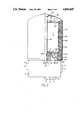
- FIG. 1 illustrates an air dryer assembly incorporating an adaptor in accordance with the invention.
- FIGS. 2, 3 and 4 illustrate alternative assemblies and
- FIGS. 5 and 6 illustrate fragmental views of further alternatives.
- the air dryer has a main body casting denoted by the block reference 1, having an input port 2 for connection to an air compressor, an output port 3 for connection to pipe leading via suitable protection valves to reservoirs of a vehicle braking system and a purge port 4 of the main body incorporating a suitable noise reducing device.
- the air dryer body 1 is provided with an externally threaded tubular spigot denoted by reference 5 which can receive a central internal thread of an air dryer cartridge of an "easy-change" type as referred to above.
- annular seal such as 9 between the cartridge and the main body 1 is drawn into sealing engagement with a flat annular sealing surface 6 of the air dryer main body.
- the seal thus effected encloses passages 2a and 2b in the air dryer body between the seal and an inlet port provided by the spigot 5 via which compressed air from the port 2 is fed into the carriage to return, after drying, via the central spigot 5 and the port 3.
- adaptation means comprising a generally annular member denoted by reference 7 is provided.
- This is typically an iron casting proceded with an annular groove 8 which receives annular seal 9 and a central internally threaded boss 10, the thread of which matches the external thread of existing spigot 5.
- the casting 7 is further provided radially inwardly of the seal 9 with a plurality of apertures such as 11 and a plurality of apertures such as 12, disposed around a central bore 13 to receive a retaining bolt 14 and recessed to accommodate a retaining nut 28.
- the retaining bolt 14 serves to retain an outer generally cylindrical container 15 with its open end in sealing engagement with the periphery 16 of the casting 7 via an ⁇ O ⁇ ring seal 17.
- the head 19 is welded to the closed upper end of the container and a projection 18 engages with a slot in the edge of the open end of the container 15 to prevent relative rotation between 15 and 7.
- Within the main container 15 there is provided in the path of incoming air via port 11, firstly an aluminium mesh filter 20, secondly, a generally cylindrical felt filter 21 and thirdly the main mass of dessicant granules 22 contained in a suitable inner container 23.
- the lower end of 23 has an aperture provided with a seal 24 which engages against the central boss 10 of the part 7
- the inner container 23 has a central tube 29 to receive the retaining bolt 14 and the lower end of the container has a perforated fabric covered plate 25.
- the upper end of the container has a similar fabric covered retaining plate 26 which rests against the dessicant granules 22 and is acted upon by a compressed spring 27 bearing against the upper end of the outer container 15.
- the flow of compressed air is as indicated by the arrows shown in the drawing of FIG. 1.
- the container 15 can be removed from member 7 after detaching the nut 28 from retaining bolt 14 and any necessary service replacement of 20 and 21, desiccant 22 and plates 25, 26 can be readily effected before reassembly of the outer container 15 to the casting and replacing same on the body 1.
- the casting 7 may itself be provided with a thread within its central bore 13 and the weld 19a may be replaced by sealing means permitting rotation of 18 relative to the housing 15. With such an embodiment the housing 15 may then be removed for servicing without removing the casting 7 from the body 1 of the air dryer.
- FIG. 2 this shows an alternative embodiment of an air dryer wherein the adaptation includes a suitably corrosion-protected pressed steel member 31, and disposed centrally welded into a recess 32 there is a threaded nut member 33 for receiving the threaded end 34 of a bolt 35.
- the head of bolt 35 is welded at 36 into a depression in the upper end of the housing 42.
- the nut member 33 has an annular recess 37 for receiving the spigot 5 of the air dryer body 1 and a lock nut 37a, if fitted, will enable 33 to be unscrewed from 5 by rotation of 35.
- the interior of the housing 42 is similar to that described above with reference to FIG. 1, in that it houses an aluminium mesh filter 43, a felt filter 44 and a mass of desiccant granules 45 contained in a cylindrical container 46 with retaining plates 47 and 48 maintained under compression by a spring 49.
- incoming air follows the path of the arrows as before and passes through the mesh filter 43, the felt filter 44 and the desiccant 45, in that order, before being delivered via the interior of the central spigot 5 to the output port of the body 1.
- a suitable strap wrench whereby it is unscrewed from the spigot 5.
- the lock nut (if fitted) 37a is removed followed by 33 thereby permitting the housing 42 to be dismantled from member 31 adaptor to provide access to the interior for replacement of the filters and desiccant before reassembly in the reverse order.
- FIG. 3 shows an alternative embodiment of the invention wherein the adaptation comprises a container 63 formed largely of suitably corrosion protected pressed steel.
- An upwradly extending cylindrical wall 50 itself provides a cylindrical part of an outer container for the filters and desiccant.
- the upper end of the housing 50 is open and has a separate closure member 51 which sealingly engages with a lip 52 via the seal 53.
- the closure member has welded thereto, at 54, the head of a retaining bolt 55, the lower threaded end 56 of which is retained in a threaded nut member 57.
- a locking nut 58 is also provided optionally.
- the member 57 has an annular recess 59 which is internally threaded to receive the spigot 5 of the air dryer.
- the underside of 63 the adaptor has welded thereto a pressed steel annular portion 60 shaped to receive a seal 61 for sealing against the upper face of the air dryer body 1.
- the interior of the housing formed by the cylindrical wall 50 of the adaptor is provided with a crushed aluminium filter 62 & felt filter 63a lining the wall of 63.
- a central mass 64 of desiccant granules is contained again in a container 65 by fabric covered perforated end plates 66 and 67, under the influence of a compression spring 68 as before.
- closure member 51 is removed by unscrewing from the spigot 5 by a suitable socket spanner on the hexagonal head of the bolt 55. Following this the closure member 51 is removed after detaching the locking nut 58 to provide access to the interior for replacement of the filters and desiccant and plates 66 and 67 before assembly in the reverse order.
- the adaptation employs a cast annular member 71 arranged to accommodate annular seals 72 and 73 similar to those of FIG. 1, but the threaded spigot 5 of the air dryer main body is fitted with a separate inverted cup-shaped member 74 which is internally threaded at 75 and 76 to respectively receive the threads of the spigot 5 and the threaded axial bolt.
- bolt 77 which has an upper ⁇ O ⁇ ring 85 under its head, is screwed into position it traps the annular member 71 between the cylindrical container 78 and the main air dryer body.
- a disposeable inner desiccant container 78 which is of light construction to include a cylindrical wall and fabric covered perforated end plates 80a and 80b slideable within 79 over a central tube 81.
- a captive spring 82 in the outer container bears against upper plate 80a to maintain the contained desiccant compacted in operation.
- the lower end of the inner container 79 is provided with an annular lower end shaped to rest against an annular crushed aluminium felt filter element 83 and to sealingly engage an ⁇ O ⁇ ring seal 84 carried by member 74.
- the generally annular part such as 7 of FIG. 1 is provided with or accompanied by an internally threaded boss which threadedly engages an externally threaded spigot which defines a central air outflow passage.
- a spigot may not be provided or may simply be detachable from the main body casting of the air dryer.
- the externally threaded spigot may then be substituted by a single member as shown at 86 in the fragmental view of FIG. 5 which takes the place of the two members 74 and 75 of FIG. 4.
- FIG. 6 shows yet another alternative wherein the rather bulky member 86 of Fig. 5 is replaced by a simpler internally and externally threaded member 88 and the flow path between the second passage of the main body and the inerior of the container is provided via an axial drilling 89 in a lower end portion of the axial screw threaded hold 87.
- FIGS. 1 to 3 the internal desiccant containers are rechargeable whereas the internal containers in FIGS. 4, 5 and 6 are disposable either is merely a matter of practical choice in each case.
- the outer container of the adaptation may be constructed of relatively heavy gauge material such as mild steel and the thickness is not limited by a need to effect a seaming closure as is the case with a cartridge of the "easy-change” type.
- the adaptation is readily incorporated to an air dryer designed to initially receive cartridge of the "easy-change” type.
Abstract
Description
Claims (9)
Applications Claiming Priority (2)
| Application Number | Priority Date | Filing Date | Title |
|---|---|---|---|
| GB8700803 | 1987-01-15 | ||
| GB878700803A GB8700803D0 (en) | 1987-01-15 | 1987-01-15 | Gas drying apparatus |
Publications (1)
| Publication Number | Publication Date |
|---|---|
| US4816047A true US4816047A (en) | 1989-03-28 |
Family
ID=10610683
Family Applications (1)
| Application Number | Title | Priority Date | Filing Date |
|---|---|---|---|
| US07/143,907 Expired - Fee Related US4816047A (en) | 1987-01-15 | 1988-01-13 | Gas drying apparatus |
Country Status (5)
| Country | Link |
|---|---|
| US (1) | US4816047A (en) |
| EP (1) | EP0275201B1 (en) |
| DE (1) | DE3888548T2 (en) |
| ES (1) | ES2050702T3 (en) |
| GB (2) | GB8700803D0 (en) |
Cited By (26)
| Publication number | Priority date | Publication date | Assignee | Title |
|---|---|---|---|---|
| US4946485A (en) * | 1988-10-18 | 1990-08-07 | Garphyttan Haldex Ab | Air drier tower |
| US5046921A (en) * | 1989-07-04 | 1991-09-10 | Nippon Air Brake Co., Ltd. | Moisture-removal device for a compressed air system |
| US5427609A (en) * | 1993-09-14 | 1995-06-27 | Horton Industries, Inc. | Device for cleaning and drying compressed gas |
| US5522150A (en) * | 1994-02-14 | 1996-06-04 | Allied Signal Truck Brake Systems | Modular air dryer for compressed air with dessicant |
| US5575541A (en) * | 1995-06-26 | 1996-11-19 | Alliedsignal Truck Brake Systems Co. | Air supply system and method with enhanced purge capacity |
| US5607500A (en) * | 1995-07-05 | 1997-03-04 | Alliedsignal Truck Brake Systems Co. | Desiccant air dryer with combined attachment and air flow management component |
| US5622544A (en) * | 1995-07-05 | 1997-04-22 | Alliedsignal Truck Brake Systems Company | Air dryer cartridge with filter retainer |
| US5689893A (en) * | 1996-09-13 | 1997-11-25 | Westinghouse Air Brake Company | Desiccant canister with positioning bore |
| US5779772A (en) * | 1994-03-22 | 1998-07-14 | Knorr Bremse Systeme Fur Nutzfahrzeuge Gmbh | Air drying cartridge for vehicles' compressed-air brake system |
| AU720954B2 (en) * | 1996-09-13 | 2000-06-15 | Westinghouse Air Brake Technologies Corporation | Regenerative desiccant air dryer |
| US6558457B1 (en) * | 1999-11-20 | 2003-05-06 | Filterwerk Mann & Hummel Gmbh | Drying agent box |
| US20040154187A1 (en) * | 2003-02-06 | 2004-08-12 | Fred Hoffman | Remote purge drying unit for compressed gas |
| US20040163535A1 (en) * | 2002-07-26 | 2004-08-26 | Bendix Commercial Vehicle Systems Llc | Spin-on desiccant cartridge with integral oil removal filter |
| US20050283991A1 (en) * | 2004-06-24 | 2005-12-29 | Mckenzie John R | Two-stage apparatus for the removal of moisture from a gas flow and insert for same |
| US7416586B1 (en) * | 2005-10-18 | 2008-08-26 | Rix Industries | Filter apparatus for extracting water vapors from a gas |
| US20080289505A1 (en) * | 2005-05-16 | 2008-11-27 | Wabco Automotive Uk Limited | Air Dryer Cartridge |
| US20080307965A1 (en) * | 2007-06-15 | 2008-12-18 | Bendix Commercial Vehicle Systems Llc | Air dryer with oil removal filter |
| US20090107505A1 (en) * | 2007-10-24 | 2009-04-30 | Drager Medical Ag & Co. Kg | Disposable absorber with adapter and lip seal |
| US20090199522A1 (en) * | 2006-08-08 | 2009-08-13 | Knorr-Bremse Systeme Fuer Nutzfahrzeuge Gmbh | Compressed Air Supply Device |
| US20130087046A1 (en) * | 2011-10-10 | 2013-04-11 | Haldex Brake Products Gmbh | Air Dryer Cartridge |
| US20140013956A1 (en) * | 2012-01-05 | 2014-01-16 | Suburban Manufacturing, Inc. | Regenerative air dryer |
| CN103691262A (en) * | 2014-01-03 | 2014-04-02 | 江苏岱洛医疗科技有限公司 | Separator of drier |
| CN105833671A (en) * | 2015-11-18 | 2016-08-10 | 武汉市天虹仪表有限责任公司 | Gas dryer |
| US10183658B2 (en) * | 2014-10-28 | 2019-01-22 | Parker-Hannifin Corporation | Combined oil and water separator in an air brake dryer |
| US11162211B1 (en) * | 2018-03-05 | 2021-11-02 | Kim Jedlicka | Fabric drying apparatus |
| US11344843B1 (en) * | 2020-12-18 | 2022-05-31 | Semyungtech Co., Ltd. | Air dryer cartridge |
Families Citing this family (5)
| Publication number | Priority date | Publication date | Assignee | Title |
|---|---|---|---|---|
| GB9101887D0 (en) * | 1991-01-29 | 1991-03-13 | Bendix Ltd | Improvements to gas drying apparatus |
| DE4339758A1 (en) * | 1993-11-22 | 1995-05-24 | Knorr Bremse Systeme | Drying cartridge for air drying systems, in particular for compressed air braking systems in vehicles |
| DE19650186A1 (en) * | 1996-12-04 | 1998-06-10 | Knecht Filterwerke Gmbh | Air dryer for pneumatic braking systems |
| DE19721230A1 (en) * | 1997-05-21 | 1998-11-26 | Knecht Filterwerke Gmbh | Air drying cartridge |
| DE102015013278B3 (en) * | 2015-10-13 | 2017-02-16 | Daimler Ag | Air dryer cartridge for an air drying device of a vehicle, assembly and vehicle |
Citations (16)
| Publication number | Priority date | Publication date | Assignee | Title |
|---|---|---|---|---|
| US3323292A (en) * | 1964-12-01 | 1967-06-06 | Dielectric Products Engineerin | Apparatus for fractionating gaseous mixtures |
| US3464186A (en) * | 1967-02-10 | 1969-09-02 | Hankison Corp | Dryer for compressed fluid systems |
| US3472000A (en) * | 1968-04-29 | 1969-10-14 | Westinghouse Air Brake Co | Air dryer and purge control unit |
| US3507097A (en) * | 1964-04-09 | 1970-04-21 | Abcor Inc | Gas fractionating apparatus |
| US3796025A (en) * | 1971-12-23 | 1974-03-12 | Bendix Corp | Absorptive dryer having oil mist eliminating apparatus |
| US4026685A (en) * | 1975-12-16 | 1977-05-31 | Wagner Electric Corporation | Flow reversing regenerative air dryer |
| GB2103954A (en) * | 1982-07-09 | 1983-03-02 | Bosch Gmbh Robert | An air drying arrangement |
| US4398929A (en) * | 1980-12-09 | 1983-08-16 | Sab Automotive Ab | Compressed air dehumidifier |
| GB2126124A (en) * | 1982-09-03 | 1984-03-21 | Bosch Gmbh Robert | A drying device for air dryers |
| JPS6022555A (en) * | 1983-07-14 | 1985-02-05 | Nippon Air Brake Co Ltd | Air dryer device for vehicle |
| US4544385A (en) * | 1983-09-13 | 1985-10-01 | Nippon Air Brake Co., Ltd. | Air dryer device for compressed air system of vehicle |
| US4572725A (en) * | 1983-12-30 | 1986-02-25 | Nippon Air Brake Co., Ltd. | Air dryer device |
| US4581047A (en) * | 1984-04-19 | 1986-04-08 | Sab Automotive Ab | Compressed air drier |
| DE3523406A1 (en) * | 1985-06-29 | 1987-01-08 | Bosch Gmbh Robert | AIR DRYER FOR COMPRESSED AIR SYSTEMS |
| US4655801A (en) * | 1984-08-21 | 1987-04-07 | Nippon Air Brake Co., Ltd. | Air dryer unit |
| DE3606817A1 (en) * | 1986-03-03 | 1987-09-10 | Wabco Westinghouse Fahrzeug | DRYING CARTRIDGE |
Family Cites Families (3)
| Publication number | Priority date | Publication date | Assignee | Title |
|---|---|---|---|---|
| FR2325419A1 (en) * | 1975-09-24 | 1977-04-22 | Alsthom Cgee | VERTICAL SUSPENSION COMPRESSED AIR DRYER |
| US4385913A (en) * | 1981-11-27 | 1983-05-31 | Lane Arlo E | Device for eliminating droplets of liquid from a gas stream |
| DE3311682A1 (en) * | 1983-03-30 | 1984-10-04 | Knorr-Bremse GmbH, 8000 München | AIR DRYER |
-
1987
- 1987-01-15 GB GB878700803A patent/GB8700803D0/en active Pending
-
1988
- 1988-01-13 US US07/143,907 patent/US4816047A/en not_active Expired - Fee Related
- 1988-01-14 GB GB8800799A patent/GB2199768B/en not_active Expired - Lifetime
- 1988-01-14 ES ES88300290T patent/ES2050702T3/en not_active Expired - Lifetime
- 1988-01-14 DE DE3888548T patent/DE3888548T2/en not_active Expired - Lifetime
- 1988-01-14 EP EP88300290A patent/EP0275201B1/en not_active Expired - Lifetime
Patent Citations (16)
| Publication number | Priority date | Publication date | Assignee | Title |
|---|---|---|---|---|
| US3507097A (en) * | 1964-04-09 | 1970-04-21 | Abcor Inc | Gas fractionating apparatus |
| US3323292A (en) * | 1964-12-01 | 1967-06-06 | Dielectric Products Engineerin | Apparatus for fractionating gaseous mixtures |
| US3464186A (en) * | 1967-02-10 | 1969-09-02 | Hankison Corp | Dryer for compressed fluid systems |
| US3472000A (en) * | 1968-04-29 | 1969-10-14 | Westinghouse Air Brake Co | Air dryer and purge control unit |
| US3796025A (en) * | 1971-12-23 | 1974-03-12 | Bendix Corp | Absorptive dryer having oil mist eliminating apparatus |
| US4026685A (en) * | 1975-12-16 | 1977-05-31 | Wagner Electric Corporation | Flow reversing regenerative air dryer |
| US4398929A (en) * | 1980-12-09 | 1983-08-16 | Sab Automotive Ab | Compressed air dehumidifier |
| GB2103954A (en) * | 1982-07-09 | 1983-03-02 | Bosch Gmbh Robert | An air drying arrangement |
| GB2126124A (en) * | 1982-09-03 | 1984-03-21 | Bosch Gmbh Robert | A drying device for air dryers |
| JPS6022555A (en) * | 1983-07-14 | 1985-02-05 | Nippon Air Brake Co Ltd | Air dryer device for vehicle |
| US4544385A (en) * | 1983-09-13 | 1985-10-01 | Nippon Air Brake Co., Ltd. | Air dryer device for compressed air system of vehicle |
| US4572725A (en) * | 1983-12-30 | 1986-02-25 | Nippon Air Brake Co., Ltd. | Air dryer device |
| US4581047A (en) * | 1984-04-19 | 1986-04-08 | Sab Automotive Ab | Compressed air drier |
| US4655801A (en) * | 1984-08-21 | 1987-04-07 | Nippon Air Brake Co., Ltd. | Air dryer unit |
| DE3523406A1 (en) * | 1985-06-29 | 1987-01-08 | Bosch Gmbh Robert | AIR DRYER FOR COMPRESSED AIR SYSTEMS |
| DE3606817A1 (en) * | 1986-03-03 | 1987-09-10 | Wabco Westinghouse Fahrzeug | DRYING CARTRIDGE |
Cited By (44)
| Publication number | Priority date | Publication date | Assignee | Title |
|---|---|---|---|---|
| US4946485A (en) * | 1988-10-18 | 1990-08-07 | Garphyttan Haldex Ab | Air drier tower |
| US5046921A (en) * | 1989-07-04 | 1991-09-10 | Nippon Air Brake Co., Ltd. | Moisture-removal device for a compressed air system |
| US5427609A (en) * | 1993-09-14 | 1995-06-27 | Horton Industries, Inc. | Device for cleaning and drying compressed gas |
| US5522150A (en) * | 1994-02-14 | 1996-06-04 | Allied Signal Truck Brake Systems | Modular air dryer for compressed air with dessicant |
| US5779772A (en) * | 1994-03-22 | 1998-07-14 | Knorr Bremse Systeme Fur Nutzfahrzeuge Gmbh | Air drying cartridge for vehicles' compressed-air brake system |
| DE4409871C2 (en) * | 1994-03-22 | 2001-08-30 | Knorr Bremse Systeme | Drying cartridge for air drying systems of compressed air braking systems of vehicles |
| US5792245A (en) * | 1994-03-22 | 1998-08-11 | Knorr Bremse Systeme Fur Nutzfahrzeuge Gmbh | Drying cartridge for air drying installations, especially for compressed-air brake systems of vehicles |
| US5575541A (en) * | 1995-06-26 | 1996-11-19 | Alliedsignal Truck Brake Systems Co. | Air supply system and method with enhanced purge capacity |
| US5622544A (en) * | 1995-07-05 | 1997-04-22 | Alliedsignal Truck Brake Systems Company | Air dryer cartridge with filter retainer |
| US5607500A (en) * | 1995-07-05 | 1997-03-04 | Alliedsignal Truck Brake Systems Co. | Desiccant air dryer with combined attachment and air flow management component |
| US5689893A (en) * | 1996-09-13 | 1997-11-25 | Westinghouse Air Brake Company | Desiccant canister with positioning bore |
| AU719621B2 (en) * | 1996-09-13 | 2000-05-11 | Westinghouse Air Brake Company | Desiccant canister with positioning bore |
| AU720954B2 (en) * | 1996-09-13 | 2000-06-15 | Westinghouse Air Brake Technologies Corporation | Regenerative desiccant air dryer |
| US6558457B1 (en) * | 1999-11-20 | 2003-05-06 | Filterwerk Mann & Hummel Gmbh | Drying agent box |
| US6951581B2 (en) * | 2002-07-26 | 2005-10-04 | Bendix Commercial Vehicle Systems Llc | Spin-on desiccant cartridge with integral oil removal filter |
| US20040163535A1 (en) * | 2002-07-26 | 2004-08-26 | Bendix Commercial Vehicle Systems Llc | Spin-on desiccant cartridge with integral oil removal filter |
| US6786953B2 (en) * | 2002-07-26 | 2004-09-07 | Bendix Commercial Vehicle Systems Llc | Spin-on desiccant cartridge with integral oil removal filter |
| US6878194B2 (en) | 2003-02-06 | 2005-04-12 | Bendix Commercial Vehicle Systems Llc | Remote purge drying unit for compressed gas |
| US20040154187A1 (en) * | 2003-02-06 | 2004-08-12 | Fred Hoffman | Remote purge drying unit for compressed gas |
| US20050283991A1 (en) * | 2004-06-24 | 2005-12-29 | Mckenzie John R | Two-stage apparatus for the removal of moisture from a gas flow and insert for same |
| US20080289505A1 (en) * | 2005-05-16 | 2008-11-27 | Wabco Automotive Uk Limited | Air Dryer Cartridge |
| US7892329B2 (en) * | 2005-05-16 | 2011-02-22 | Wabco Automotive Uk Limited | Air dryer cartridge |
| US7416586B1 (en) * | 2005-10-18 | 2008-08-26 | Rix Industries | Filter apparatus for extracting water vapors from a gas |
| US8021465B2 (en) * | 2006-08-08 | 2011-09-20 | Knorr-Bremse Systeme Fuer Nutzfahrzeuge Gmbh | Compressed air supply device |
| US20090199522A1 (en) * | 2006-08-08 | 2009-08-13 | Knorr-Bremse Systeme Fuer Nutzfahrzeuge Gmbh | Compressed Air Supply Device |
| US20090199523A1 (en) * | 2006-08-08 | 2009-08-13 | Knorr-Bremse Systeme Fuer Nutzfahrzeuge Gmbh | Compressed Air Supply Device |
| US7972418B2 (en) * | 2006-08-08 | 2011-07-05 | Knorr-Bremse Systeme Fuer Nutzfahrzeuge Gmbh | Compressed air supply device |
| US20080307965A1 (en) * | 2007-06-15 | 2008-12-18 | Bendix Commercial Vehicle Systems Llc | Air dryer with oil removal filter |
| US7789950B2 (en) * | 2007-06-15 | 2010-09-07 | Bendix Commercial Vehicle Systems Llc | Air dryer with oil removal filter |
| US20090107505A1 (en) * | 2007-10-24 | 2009-04-30 | Drager Medical Ag & Co. Kg | Disposable absorber with adapter and lip seal |
| US7850765B2 (en) * | 2007-10-24 | 2010-12-14 | Dräger Medical GmbH | Disposable absorber with adapter and lip seal |
| US8906146B2 (en) * | 2011-10-10 | 2014-12-09 | Haldex Brake Products Gmbh | Air dryer cartridge |
| US20130087046A1 (en) * | 2011-10-10 | 2013-04-11 | Haldex Brake Products Gmbh | Air Dryer Cartridge |
| CN103071372A (en) * | 2011-10-10 | 2013-05-01 | 哈尔德克斯刹车产品有限公司 | Air drying cartridge |
| US8999045B2 (en) * | 2012-01-05 | 2015-04-07 | Suburban Manufacturing, Inc. | Regenerative air dryer |
| US20140013956A1 (en) * | 2012-01-05 | 2014-01-16 | Suburban Manufacturing, Inc. | Regenerative air dryer |
| US9724636B2 (en) | 2012-01-05 | 2017-08-08 | Suburban Manufacturing, Inc. | Regenerative air dryer |
| US10596511B2 (en) | 2012-01-05 | 2020-03-24 | Suburban Manufacturing, Inc. | Regenerative air dryer |
| CN103691262A (en) * | 2014-01-03 | 2014-04-02 | 江苏岱洛医疗科技有限公司 | Separator of drier |
| US10183658B2 (en) * | 2014-10-28 | 2019-01-22 | Parker-Hannifin Corporation | Combined oil and water separator in an air brake dryer |
| US10625727B2 (en) | 2014-10-28 | 2020-04-21 | Parker-Hannifin Corporation | Combined oil and water separator in an air brake dryer |
| CN105833671A (en) * | 2015-11-18 | 2016-08-10 | 武汉市天虹仪表有限责任公司 | Gas dryer |
| US11162211B1 (en) * | 2018-03-05 | 2021-11-02 | Kim Jedlicka | Fabric drying apparatus |
| US11344843B1 (en) * | 2020-12-18 | 2022-05-31 | Semyungtech Co., Ltd. | Air dryer cartridge |
Also Published As
| Publication number | Publication date |
|---|---|
| DE3888548D1 (en) | 1994-04-28 |
| GB8800799D0 (en) | 1988-02-17 |
| EP0275201B1 (en) | 1994-03-23 |
| DE3888548T2 (en) | 1994-09-29 |
| EP0275201A1 (en) | 1988-07-20 |
| ES2050702T3 (en) | 1994-06-01 |
| GB2199768B (en) | 1990-11-28 |
| GB2199768A (en) | 1988-07-20 |
| GB8700803D0 (en) | 1987-02-18 |
Similar Documents
| Publication | Publication Date | Title |
|---|---|---|
| US4816047A (en) | Gas drying apparatus | |
| US5779772A (en) | Air drying cartridge for vehicles' compressed-air brake system | |
| JP3812595B2 (en) | Air dryer cartridge mounting system | |
| US5110327A (en) | Compressed air dryer | |
| US7097696B2 (en) | Dual cartridge air dryer with oil separator and readily changeable valves | |
| AU2008242470B2 (en) | Air dryer with pre-filter | |
| CA2684739C (en) | Membrane air dryer with sweep air control | |
| US4498898A (en) | Centrifugal separator | |
| US6319296B1 (en) | Air system bypass for oil separator | |
| US6527839B2 (en) | Spin-on filtering oil removal cartridge | |
| EP0608606B1 (en) | Gas drying apparatus | |
| US20010002007A1 (en) | Easy-change fuel filter | |
| GB2120134A (en) | Centrifugal separator |
Legal Events
| Date | Code | Title | Description |
|---|---|---|---|
| AS | Assignment |
Owner name: BENDIX LIMITED, BRISTOL, ENGLAND, A COMPANY OF GRE Free format text: ASSIGNMENT OF ASSIGNORS INTEREST.;ASSIGNOR:NEAL, BRIAN P.;REEL/FRAME:004854/0560 Effective date: 19880107 Owner name: BENDIX LIMITED, A COMPANY OF GREAT BRITAIN,ENGLAND Free format text: ASSIGNMENT OF ASSIGNORS INTEREST;ASSIGNOR:NEAL, BRIAN P.;REEL/FRAME:004854/0560 Effective date: 19880107 |
|
| FPAY | Fee payment |
Year of fee payment: 4 |
|
| REMI | Maintenance fee reminder mailed | ||
| LAPS | Lapse for failure to pay maintenance fees | ||
| FP | Lapsed due to failure to pay maintenance fee |
Effective date: 19970402 |
|
| STCH | Information on status: patent discontinuation |
Free format text: PATENT EXPIRED DUE TO NONPAYMENT OF MAINTENANCE FEES UNDER 37 CFR 1.362 |