US4819322A - Method for manufacturing a flat coil - Google Patents

Method for manufacturing a flat coil Download PDF

Info

Publication number
US4819322A
US4819322A US07/058,560 US5856087A US4819322A US 4819322 A US4819322 A US 4819322A US 5856087 A US5856087 A US 5856087A US 4819322 A US4819322 A US 4819322A
Authority
US
United States
Prior art keywords
rolled
coil
metal foil
discharge machining
electric discharge
Prior art date
Legal status (The legal status is an assumption and is not a legal conclusion. Google has not performed a legal analysis and makes no representation as to the accuracy of the status listed.)
Expired - Fee Related
Application number
US07/058,560
Inventor
Shigetaka Higuchi
Isao Noguchi
Shuji Kurita
Yasutomo Kodachi
Current Assignee (The listed assignees may be inaccurate. Google has not performed a legal analysis and makes no representation or warranty as to the accuracy of the list.)
Sony Corp
Original Assignee
Sony Corp
Priority date (The priority date is an assumption and is not a legal conclusion. Google has not performed a legal analysis and makes no representation as to the accuracy of the date listed.)
Filing date
Publication date
Priority claimed from JP61132513A external-priority patent/JPS62290116A/en
Priority claimed from JP62022028A external-priority patent/JPS63188906A/en
Application filed by Sony Corp filed Critical Sony Corp
Assigned to SONY CORPORATION reassignment SONY CORPORATION ASSIGNMENT OF ASSIGNORS INTEREST. Assignors: KODACHI, YASUTOMO, KURITA, SHUJI, NOGUCHI, ISAO, HIGUCHI, SHIGETAKA
Application granted granted Critical
Publication of US4819322A publication Critical patent/US4819322A/en
Anticipated expiration legal-status Critical
Expired - Fee Related legal-status Critical Current

Links

Images

Classifications

    • HELECTRICITY
    • H02GENERATION; CONVERSION OR DISTRIBUTION OF ELECTRIC POWER
    • H02KDYNAMO-ELECTRIC MACHINES
    • H02K15/00Methods or apparatus specially adapted for manufacturing, assembling, maintaining or repairing of dynamo-electric machines
    • H02K15/04Methods or apparatus specially adapted for manufacturing, assembling, maintaining or repairing of dynamo-electric machines of windings, prior to mounting into machines
    • H02K15/0435Wound windings
    • HELECTRICITY
    • H01ELECTRIC ELEMENTS
    • H01FMAGNETS; INDUCTANCES; TRANSFORMERS; SELECTION OF MATERIALS FOR THEIR MAGNETIC PROPERTIES
    • H01F41/00Apparatus or processes specially adapted for manufacturing or assembling magnets, inductances or transformers; Apparatus or processes specially adapted for manufacturing materials characterised by their magnetic properties
    • H01F41/02Apparatus or processes specially adapted for manufacturing or assembling magnets, inductances or transformers; Apparatus or processes specially adapted for manufacturing materials characterised by their magnetic properties for manufacturing cores, coils, or magnets
    • H01F41/04Apparatus or processes specially adapted for manufacturing or assembling magnets, inductances or transformers; Apparatus or processes specially adapted for manufacturing materials characterised by their magnetic properties for manufacturing cores, coils, or magnets for manufacturing coils
    • HELECTRICITY
    • H01ELECTRIC ELEMENTS
    • H01FMAGNETS; INDUCTANCES; TRANSFORMERS; SELECTION OF MATERIALS FOR THEIR MAGNETIC PROPERTIES
    • H01F5/00Coils
    • YGENERAL TAGGING OF NEW TECHNOLOGICAL DEVELOPMENTS; GENERAL TAGGING OF CROSS-SECTIONAL TECHNOLOGIES SPANNING OVER SEVERAL SECTIONS OF THE IPC; TECHNICAL SUBJECTS COVERED BY FORMER USPC CROSS-REFERENCE ART COLLECTIONS [XRACs] AND DIGESTS
    • Y10TECHNICAL SUBJECTS COVERED BY FORMER USPC
    • Y10TTECHNICAL SUBJECTS COVERED BY FORMER US CLASSIFICATION
    • Y10T29/00Metal working
    • Y10T29/49Method of mechanical manufacture
    • Y10T29/49002Electrical device making
    • Y10T29/4902Electromagnet, transformer or inductor
    • Y10T29/49071Electromagnet, transformer or inductor by winding or coiling
    • YGENERAL TAGGING OF NEW TECHNOLOGICAL DEVELOPMENTS; GENERAL TAGGING OF CROSS-SECTIONAL TECHNOLOGIES SPANNING OVER SEVERAL SECTIONS OF THE IPC; TECHNICAL SUBJECTS COVERED BY FORMER USPC CROSS-REFERENCE ART COLLECTIONS [XRACs] AND DIGESTS
    • Y10TECHNICAL SUBJECTS COVERED BY FORMER USPC
    • Y10TTECHNICAL SUBJECTS COVERED BY FORMER US CLASSIFICATION
    • Y10T29/00Metal working
    • Y10T29/49Method of mechanical manufacture
    • Y10T29/49002Electrical device making
    • Y10T29/4902Electromagnet, transformer or inductor
    • Y10T29/49073Electromagnet, transformer or inductor by assembling coil and core

Definitions

  • the present invention relates to a process for producing a flat coil for use in an electric motor, a deflecting coil, a transformer or the like and is specifically directed to a process for producing a flat coil by cutting up the rolled body of metal foil.
  • a coil of the wound type utilizing a copper wire wound in layers is employed as a coil for an electric motor or in the deflecting yoke of a cathode ray tube.
  • the so called flat coils of very substantially reduced thickness have been developed and put into practical use.
  • a sheet coil can be produced by etching a sheet of copper foil laminated with an insulator sheet in a spiral pattern in a line having a width of 50 microns or so and used as a coil for a flat motor.
  • Employing such a thin sheet coil significantly contributes to flattening and miniaturizing of motors.
  • a flat coil produced by this process still has drawbacks in that it is deformed as a result of the cutting and that the strength of the terminal portions is not sufficient.
  • the present invention provides a process for producing a flat coil which eliminates drawbacks of the conventional processes as described above, and by which flat coils of high reliability can be produced with a high productivity and without causing short-circuits after a rolled up body of the metal foil is cut.
  • the present invention provides a process for producing a flat coil which permits effective cutting of a rolled up body of conductor foil at high speed and at high productivity even where the strength of the conductor foil is very low.
  • the present invention makes use of electric discharge machining of a rolled up body of metal foil.
  • there is formed an insulator layer on a ribbon of metal foil and the resulting metal foil with the attached insulator layer is formed around a center shaft or mandrel while pressing the insulator layer toward the center shaft to form a rolled up body of metal foil.
  • the rolled up body is then cut in a direction transverse to the center shaft into flat coils of a predetermined thickness by electric discharge machining.
  • a flat coil which comprises alternating metal foil layers and insulated layers which project beyond the metal layers in cross section of the flat coil.
  • the flat coil is produced by cutting through the use of electric discharge machining on a rolled up body of metal foil or a block coil consisting of a rolled up body of metal foil formed by winding metal foil and an insulator film into alternate layers to form a plurality of slices each of which provides a flat coil.
  • a process for producing a flat coil which includes the steps of forming an insulator layer on the metal foil, winding the metal foil with the insulator formed thereon about a center shaft while pressing the insulator layer toward the center shaft to form a rolled up body of metal foil, and attaching a metal electrode member in the form of a strip in an integral relationship to at least the inner or outer periphery of rolled up body over the entire width thereof, thereby forming a coil block.
  • This block is cut in a direction transverse to the center shaft into flat coils of a predetermined thickness by electric discharge machining.
  • a process for producing a flat coil which includes the steps of forming an insulator layer on the metal foil, winding the metal foil with the insulator layer thereon about a center shaft while pressing the insulator layer toward the center shaft to form a rolled up body of metal foil, attaching a metal terminal member in the form of a strip in integral relationship to an inner or outer periphery of the rolled up body over the entire width of the rolled up body so as to electrically connect the strip to the metal foil of the rolled up body.
  • An insulating layer of resin is formed at a terminal end portion of the metal foil at its outermost turn, and the outer periphery of the rolled up body other than the insulating resin layer is covered with a metal reinforcing layer produced by electroplating to form a coil block.
  • This coil block is then cut in a direction transverse to the center shaft into flat coils of a predetermined thickness by electric discharge machining.
  • the formation of the metal reinforcing layer is also advantageous for the production of flat coils because the strength at the outer periphery of the rolled up body is increased. Accordingly, the processing conditions can be made more severe and an increase in cutting speed can be achieved.
  • the metal reinforcing layer acts to protect the conductor foil on the outer periphery of the flat coil, and so a rolled up body can be cut composed of very thin conductor foil which has been heretofore difficult to cut by conventional means.
  • a number of rolled up bodies of metal foil can be cut at a time, so that the productivity is substantially increased.
  • FIG. 1 is a schematic illustration showing the step of forming an insulator layer on copper foil as part of the process of the present invention
  • FIG. 2 is a view in perspective showing a coil of sheet stock with an insulator layer applied thereto;
  • FIG. 3 is an enlarged, partial cross sectional view of the coil sheet of FIG. 2;
  • FIG. 4 is a view similar to FIG. 3 but showing a coil stock sheet for the case in which a high molecular weight film is not used;
  • FIG. 5 is a schematic showing of a step of cutting a coil stock sheet
  • FIG. 6 is a view similar to FIG. 5 but showing the step of winding a coil stock sheet around a core shaft;
  • FIG. 7 is a perspective view of the rolled up body wound on the core shaft
  • FIG. 8 is a similar view showing the step of attaching a solder bar or strip which is to be formed into an electrode
  • FIGS. 9A and 9B are similar views showing the completed coil blocks
  • FIG. 10 is a front elevational view, partly broken away, of a heating furnace which can be used for hardening the layer of bonding agent;
  • FIG. 11 is a schematic side elevational view showing the step of cutting a coil block by electric discharge machining
  • FIG. 12 is a schematic view illustrating an arrangement of electrodes for cutting a plurality of coil blocks at the same time
  • FIG. 13 is a schematic illustration showing a method of cutting a coil block in three directions at a time
  • FIGS. 14A to 14E are schematic illustrations showing different met of connecting a coil block to ground
  • FIG. 15 is a perspective view showing a coil block after cutting
  • FIGS. 16A and 16B are perspective views showing the flat coils obtained by the present process.
  • FIG. 17 is an enlarged cross sectional view showing a cross section of a flat coil produced by electric discharge machining.
  • FIG. 18 is a perspective view, partially broken away, showing a lapping device.
  • a layer of a bonding agent which is to act as an insulator layer is first laminated on copper foil 1 as shown in FIG. 3.
  • a film 2 of a high molecular weight compound such as a polyimide film is laminated in order to assure the insulation of products with two bonding agents layers 3 and 4 coated on opposite sides of the film 2.
  • the thickness of the copper foil 1 may be about 35 microns while the thickness of each of the bonding agent layers 3 and 4 is about 6 microns.
  • the high molecular weight film 2 is formed from a polyimide film having a thickness of about 13 microns.
  • the high molecular weight film 2 is not always required and, for example, as shown in FIG. 4, the bonding layers 3 and 4 alone may be coated directly on opposite faces of the copper foil 1.
  • the bonding agents 3, 4 may use an epoxy resin, a phenol resin, a phenoxy resin, an acrylic acid resin, an urethane resin, a polyimide, a polyamide, a mixture of the above resins, nitrile rubber, synthetic rubber, or, a mixture of nitrile or/and synthetic rubber with the above resins.
  • Lamination of the high molecular weight film 2 or bonding agent layers 3 and 4 on the copper foil 1 may be effected using a mechanism such as shown in FIG. 1.
  • a ribbon of a high molecular weight film 2 is supplied from a supply roll 11 and passed through a bonding agent applying machine 12 where a bonding agent is applied to opposite faces of the high molecular weight film 2.
  • the film 2 is passed through a drying apparatus 13 in which the bonding agent layers are dryed into a semidryed condition.
  • the high molecular weight film 2 is then passed through a laminator 14 where it is attached to a web of copper foil 1 supplied from a supply roll 15 and the laminated product is then wound up on a take-up roll 16.
  • a stock roll of a layered body 5 composed of copper foil 1, high molecular weight film 2, and bonding agent layers 3 and 4 is produced, as shown in FIG. 2.
  • the web from the layered body 5 is delivered from the roll 16 and is cut into four webs of a predetermined width using a cutting machine 17 as shown in FIG. 5.
  • the resulting ribbons are then wound onto a core shaft 6 of a substantially triangular cross section with back tension being applied thereto by tension rolls 20 in order to produce a rolled up body 7 of the layered body 5.
  • a core shaft 6 of a substantially triangular cross section with back tension being applied thereto by tension rolls 20 in order to produce a rolled up body 7 of the layered body 5.
  • three heating rolls 22 are urged toward and pressed against the layered body 5 in three directions by the action of air cylinders 21 so as to regulate the wound condition of the rolled up body 7.
  • FIG. 7 shows the appearance of a rolled up body 7 produced in this manner.
  • the shape of a cross section of the core shaft 6 may be varied in accordance with the shape desired and may, for example, be circular, elliptical, rectangular, or polygonal.
  • the conductive metal strip 8 such as a strip of solder may be mounted on the core shaft 6 in order to establish electrical connection with the innermost turn of the layered body 5 to be wound on the core shaft 6.
  • a piece of the metal strip 8 on each of the coils serves as one of the lead electrodes.
  • solder strip 9 is attached along a terminal edge of the rolled up body 7 so that when the rolled up body 7 is thereafter cut into rolls, the solder strip 9 may serve as the other lead electrode on each of the coils.
  • the solder strip 9 can readily be formed by extruding a solder material in a softened condition from a nozzle 23 as shown in FIG. 8.
  • FIG. 9A is a perspective view showing the appearance of the rolled up body 7 having a solder strip 9 attached along a side edge thereof. As seen in this figure, this results in a block 10 which includes all of the components of a coil including the rolled up body 7 of the copper foil 1, the conductive metal strip 8 which is to form an electrode, and the solder strip 9 which is to form the other electrode of the coil.
  • the block 10 will hereinafter be referred to as a coil block.
  • a coil block 10 produced by the steps described above is then placed into a heating furnace 24 as shown in FIG. 10 and heated to a predetermined temperature in order to harden fully the bonding agent layers 3 and 4 interposed between the adjacent turns or convolutions of the rolled up body 7 of the coil blocks 10. Subsequently, the coils blocks are cut into pieces of a predetermined length by an electrical discharge machining.
  • Electric discharge machining is a non-contact machining method which utilizes pulsed spark discharges at intervals of very short duration within a dielectric liquid coolant.
  • the resulting short arc discharges can be regarded as an extraordinary erosion of metal at a discharge point.
  • Such discharge machining is normally used for processing of a conductor such as formation of a metal mold, but the present inventors have found that the electric discharge machining provides good results also for cutting of a layered body of metal foil and an insulator film. Further details of electrical discharge machining and the theory thereof will be found in Volume 3, Metals Handbook, Eighth Edition (1967) pages 227 to 233. That publication is incorporated herein by reference.
  • the coil blocks 10 may be immersed in a dielectric coolant 25.
  • a pulsed current is applied to the coil blocks 10 in the dielectric coolant 25 from plate shaped electrodes 26 arranged in a predetermined spaced relationship, for example, spaced by a distance of 0.4 mm in the longitudinal direction of the core shafts 6.
  • a pulsing source having a pulse width of 3 microseconds on and 6 microseconds off, providing a pulse frequency of 111 KHz with a peak current of 10A can be produced using a 20A, 40 to 50 V power source.
  • Either water or dielectrics of petroleum base materials such as kerosene can be used as the dielectric coolant for electric discharge machining.
  • the core shaft 6 of a coil block 10 can be secured at opposite ends to a pair of opposing rotatable shafts 27 and 28 and rotated by the latter two or three times through an angle of 120° in order to cut portions of the rolled up body 7 of the coil block 10 corresponding to individual sides of the triangular shape of the core shaft 6.
  • the coil blocks 10 need not necessarily be cut one by one as it is possible, for example, to place a plurality of coil blocks 10 in parallel relationship and cut them at the same time using a plurality of plate shaped electrodes 26 arranged in a predetermined spaced relationship as shown in FIG. 12. Actually, up to 100 coils can be obtained by cutting the coil blocks 10 arranged in a juxtaposed relationship by electrical discharge by means of eleven plate shaped electrodes 26 arranged in spaced relationship by a distance of 0.4 mm.
  • the electrodes 26a, 26b, and 26c are arranged in an angularly spaced relationship by 120° to confront the three sides 6a, 6b, and 6c of the core shaft 6 of a coil block 10 so that the electrodes may cut the rolled up body 7 wound on the core shaft 6 in three directions at the same time.
  • the electrodes may be moved by a required distance to successively cut the coil block.
  • FIGS. 14A to 14D Various grounding methods are illustrated in FIGS. 14A to 14D.
  • FIG. 14A illustrates a method wherein a coil block 10 is placed on a metal fixture 29 made of a conductive metal and is grounded directly.
  • FIG. 14B illustrates another method wherein a coil block 10 is placed on a metal fixture 29 which is grounded similarly as shown in FIG. 14A, but the metal fixture 29 in this case has a groove 29a formed in which a liquid electrically conductive material 30 such as mercury is introduced in order to assure the grounded connection of the coil block 10 even after cutting of the coil block 10 proceeds.
  • a liquid electrically conductive material 30 such as mercury
  • FIG. 14C illustrates a further method wherein the core shaft 6 is formed from a conductive metal material or the like and is grounded directly.
  • FIG. 14D illustrates a still further modified form wherein the ground is connected to the solder strip 9 which extends along a side edge of the rolled up body 7 of the coil block 10.
  • the conductive metal strip 8 at the innermost portion of the rolled up body 7 may also be connected to the ground.
  • FIG. 16A shows the appearance of one of such flat coils 31 after it has been removed from the core shaft 6.
  • a flat coil 31 obtained in this manner thus includes a rolled up portion 31a of copper foil and insulators, and terminal electrodes 31b and 31c.
  • the flat coil 31 has a very small thickness, and the copper foil 1 is wound or layered very closely. Accordingly, the flat coil 31 is very effective for use as a motor coil.
  • the inventors have further observed a cut face of a flat coil formed by electric discharge machining with the aid of a microscope. Such observation reveals that, suprisingly the insulator layers 32 composed of the high molecular weight film 2 plus the bonding agent layers 3 and 4 project from the layers of copper foil 1 as shown in FIG. 17, and accordingly, the insulation between adjacent layers of the copper foil 1 is maintained completely.
  • the projections of the insulator layers 32 beyond the metal layers may be left as they are, they may optionally be removed by polishing using a lapping device 33 as shown in FIG. 18 in order to assure the accuracy of the width of the flat coil 31.
  • the flat coil 31 produced by the steps described above may be incorporated into an electric motor after other steps such as masking terminal portions, coating with a resin material, and inspecting for proper inductance, continuity resistance, and insulation testing.
  • the inventors have actually produced a flat motor having a diameter of about 2.7 mm and a thickness of 2 mm using flat coils 31 obtained in accordance with the present invention.
  • a flat coil produced in accordance with the present invention includes a coil section 31a composed of a rolled body of conductor foil and an insulator film wound into a number of convolutions until predetermined characteristics are obtained.
  • a pair of terminals 31b and 31c are located at opposite ends of the innermost and outermost turns of the rolled up body and provide portions for external connections.
  • a metal reinforcing layer 50 covers the outer periphery of the rolled up body.
  • An insulating resin layer 40 is formed by application of a resin material in the form of a belt to a terminal end 31d of the outermost turn of the coil section 31a. In this manner, the terminal end 31d of the coil section 31a is sealed by the insulating resin layer 40.
  • the metal reinforcing layer 50 is formed by electroplating a portion of the outer periphery of the coil section 31a other than the insulating resin layer 40.
  • the outermost turn of the conductor foil has a total thickness equal to the thickness of the conductor foil itself and the thickness of the metal reinforcing layer 50.
  • the flat coil with such construction as described above has the improved mechanical strength by the metal reinforcing layer 50 so that it is resistant to deformation and the like.
  • the terminal 31c provided on the outer periphery of the coil section 31a is enclosed by the metal reinforcing layer 50 and is closely contacted with the conductor foil. Accordingly, the connection of the terminal 31b through the conductor foil is assured while the mounting strength of the terminal 31c is increased.
  • the metal reinforcing layer 50 is partly cut and the insulating resin layer 40 is interposed in the cut space in the metal reinforcing layer 50, the metal reinforcing layer itself does not produce an electric loop nor deteriorate the capacity of the coil section 31a.
  • a rolled up body as shown in FIG. 9A is formed in a manner similar to the first embodiment already described.
  • the copper foil must necessarily be exposed on an outer periphery of the rolled up body 7, and accordingly attention must be paid to the winding direction of the layered body 5 as shown in FIG. 2.
  • bonding agent layers are formed on opposite faces of a high molecular weight film, it is preferable to remove in advance the bonding agent layer only on an outer face near a terminal end of an outermost turn of the high molecular weight film.
  • solder strip 9 is attached along the terminal edge of the rolled up body 7 so that when the rolled up body 7 is thereafter cut into coils, the solder strip may serve as one lead electrode on each of the coils.
  • the solder strip 9 can readily be formed by extruding solder material in a softened condition from a nozzle 23.
  • an insulator resin material is applied along the terminal end portion of the outermost turn of the rolled up body 7 to form an insulator resin layer 40 as shown in FIG. 9B.
  • Numerous resin materials can be employed as insulating resin materials 40.
  • the insulator resin may be a buthyral resin, a phenol resin, an epoxy resin, an urethane resin, or an acrylic acid resin.
  • a metal reinforcing layer 50 is coated by electrolytic plating of the entire surface of the rolled up body 7 on which the insulating resin layer 40 is provided.
  • the electrolytic plating may be copper plating, nickel plating, zinc plating, chromium plating, solder plating, tin plating or the like.
  • a metal reinforcing layer 50 is formed on a conductor portion of the rolled up body 7 but not on the insulating resin layer 40. Accordingly, the metal reinforcing layer 50 does not form an electric loop.
  • FIG. 9B is a perspective view showing the appearance of the rolled up body 7 around which the metal reinforcing layer 50 is formed.
  • a block 10 includes all the components of the coil including the rolled up body 7, the conductive metal strip 8 which is to later provide one electrode, and the solder strip 9 which is to make the other electrode of the coil, the insulating resin layer 40, and the metal reinforcing layer 50.
  • This block 10 is hereafter referred to as a coil block.
  • the coil block 10 is placed in juxtaposition to an electrode as shown in FIG. 14E and cut into flat coils having a predetermined thickness by electric discharge machining. Since the coil block 10 has a metal reinforcing layer 50 formed thereon, the machining conditions can be made severe and the entire cutting speed can be increased. The cutting speed is largely influenced by the speed upon starting of cutting, and from this point of view, the provision of the metal reinforcing layer 50 is very effective.
  • the coil block 10 can be cut and deformation of the coils after cutting of the coil block 10 can be minimized.
  • the inventors have produced flat coils under the following conditions and have confirmed improvements in cutting time and in yield rate.
  • a bonding agent was first coated with a thickness of about 5 microns after drying on a copper foil having a thickness of 35 microns.
  • the ribbon of the bonding agent coated copper foil was wound into a rolled up body as shown in FIG. 9A.
  • a resin composition having the following formulation was applied in the form of a belt to a terminal end portion of an outermost turn of the rolled up body.
  • the thickness of the applied layer was 35 microns.
  • the resin composition shown above had a solids content of 20%.
  • the rolled up body with the resin composition applied thereto was put into a copper pyrophosphoric acid plating tank, and electrolytic plating was effected.
  • the plating conditions included a current density of 3 A/dm 2 ; a plating time of 60 minutes; and a plating thickness of 45 microns.
  • a coil block as shown in FIG. 9B was obtained.
  • This coil block plated as described above was cut by electric discharge machining to produce flat coils.
  • the cutting time and the yield rate were compared with those of flat coils produced without plating. The results are shown in the Table below:
  • the cutting of the rolled up body by electric discharge machining to form separate coils can be produced conveniently by mass production.
  • a flat coil produced by the process of the present invention and having a metal reinforcing layer on an outer periphery thereof has improved mechanical strength so that deformation is not a significant problem.
  • the terminals for external connection can be attached in a stabilized condition to the flat coil, and the terminals themselves can be improved in strength.
  • the metal reinforcing layer Due to the presence of an insulating resin layer intermediate the metal reinforcing layer, the metal reinforcing layer will not form an electric loop at all and so the capacity of the coil is not deteriorated.
  • the rolled up body of conductor foil is cut by an electric discharge machining after a metal reinforcing layer has been formed on an outer peripheral portion by metal plating, even when very thin copper foil which cannot be cut by conventional cutting means is employed, a good cutting can be assured and the cutting speed can be improved.
  • the process is a very simple process which does not require a special technique or high accuracy so that the process of the invention is very high in practical value.

Abstract

A process for producing a flat coil of high reliability and free from the problem of short-circuiting, and capable of high productivity. The process includes steps of forming an insulator layer on a metal foil ribbon, winding the metal foil around a center shaft or mandrel while pressing the insulator layer toward the center shaft to form a rolled up metal foil body. A strip electrode of conductive metal may be integrally attached to the inner or outer periphery of the coil or both to provide electrical connection to the turns. An insulating resin layer may be formed at an outer end of the metal foil, and a metal reinforcing layer can be formed on the outer periphery of the rolled up body other than at the insulating resin layer by electroplating to form a coil block. The rolled up body or coil block is then cut by electric discharge machining in a direction transverse to the center shaft to form flat coils at a predetermined thickness.

Description

BACKGROUND OF THE INVENTION
1. Field of the Invention
The present invention relates to a process for producing a flat coil for use in an electric motor, a deflecting coil, a transformer or the like and is specifically directed to a process for producing a flat coil by cutting up the rolled body of metal foil.
2. DESCRIPTION OF THE PRIOR ART
Conventionally, a coil of the wound type utilizing a copper wire wound in layers is employed as a coil for an electric motor or in the deflecting yoke of a cathode ray tube. As the size of the apparatus is reduced, the so called flat coils of very substantially reduced thickness have been developed and put into practical use. For example, a sheet coil can be produced by etching a sheet of copper foil laminated with an insulator sheet in a spiral pattern in a line having a width of 50 microns or so and used as a coil for a flat motor. Employing such a thin sheet coil significantly contributes to flattening and miniaturizing of motors.
While such a sheet coil is very effective for flattening appliances, the mass production of such sheet coils is difficult because it requires an etching technique of very high accuracy. Since such a special technique is necessitated, the coils cannot be produced readily by every manufacturer.
There has been a disclosure of a process wherein a web of copper foil to which an insulator film is applied is rolled up and cut into round slices in order to produce flat coils. However, such a process has not been put into practical use due to the problems of reliability and applicability to mass production. In particular, it is difficult to cut a rolled up sheet of copper foil into round slices of a predetermined axial length, that is, into flat coils of a predetermined thickness. Where, for example, a mechanical means or a laser beam is used for such cutting, there is a possibility that a burr may be produced on a cut face which causes short-circuiting of the coil produced. In order to eliminate such a shear drop on a cut face, the face must be polished smoothly. This step normally requires very much labor and much operating time. Accordingly, the use of the proposed disclosure is not well suited for mass production.
When it is attempted to produce flat coils by cutting a rolled up body of copper foil, conventional cutting methods are not employed in mass production since their capacity does not match their cost, because processing after cutting is difficult, and because too high an overall cost is required.
For example, investigation made by the inventors of the present invention has revealed that when a rolled up body of overlapping sheets of conductor foil with an insulating film is cut by electric discharge machining, particularly where a very thin conductor foil is used, there is the possibility that the strength of a portion of the conductor foil at an outer peripheral portion thereof may be insufficient so that a so called turnup may appear. This results in reducing the cutting speed. A portion of the conductor foil at the outer peripheral portion of the coil may also be cut so that the coil thus produced is defective. In the worst case, cutting itself may be impossible.
Further, a flat coil produced by this process still has drawbacks in that it is deformed as a result of the cutting and that the strength of the terminal portions is not sufficient.
SUMMARY OF THE INVENTION
The present invention provides a process for producing a flat coil which eliminates drawbacks of the conventional processes as described above, and by which flat coils of high reliability can be produced with a high productivity and without causing short-circuits after a rolled up body of the metal foil is cut.
The present invention provides a process for producing a flat coil which permits effective cutting of a rolled up body of conductor foil at high speed and at high productivity even where the strength of the conductor foil is very low.
The present invention makes use of electric discharge machining of a rolled up body of metal foil. According to one aspect of the invention, there is formed an insulator layer on a ribbon of metal foil, and the resulting metal foil with the attached insulator layer is formed around a center shaft or mandrel while pressing the insulator layer toward the center shaft to form a rolled up body of metal foil. The rolled up body is then cut in a direction transverse to the center shaft into flat coils of a predetermined thickness by electric discharge machining.
In accordance with another aspect of the present invention, there is provided a flat coil which comprises alternating metal foil layers and insulated layers which project beyond the metal layers in cross section of the flat coil. The flat coil is produced by cutting through the use of electric discharge machining on a rolled up body of metal foil or a block coil consisting of a rolled up body of metal foil formed by winding metal foil and an insulator film into alternate layers to form a plurality of slices each of which provides a flat coil.
In accordance with another aspect of the present invention, there is provided a process for producing a flat coil which includes the steps of forming an insulator layer on the metal foil, winding the metal foil with the insulator formed thereon about a center shaft while pressing the insulator layer toward the center shaft to form a rolled up body of metal foil, and attaching a metal electrode member in the form of a strip in an integral relationship to at least the inner or outer periphery of rolled up body over the entire width thereof, thereby forming a coil block. This block is cut in a direction transverse to the center shaft into flat coils of a predetermined thickness by electric discharge machining.
In a still further embodiment of the invention, there is provided a process for producing a flat coil which includes the steps of forming an insulator layer on the metal foil, winding the metal foil with the insulator layer thereon about a center shaft while pressing the insulator layer toward the center shaft to form a rolled up body of metal foil, attaching a metal terminal member in the form of a strip in integral relationship to an inner or outer periphery of the rolled up body over the entire width of the rolled up body so as to electrically connect the strip to the metal foil of the rolled up body. An insulating layer of resin is formed at a terminal end portion of the metal foil at its outermost turn, and the outer periphery of the rolled up body other than the insulating resin layer is covered with a metal reinforcing layer produced by electroplating to form a coil block. This coil block is then cut in a direction transverse to the center shaft into flat coils of a predetermined thickness by electric discharge machining.
When a rolled up body of metal foil with an insulator film laminated thereto is cut by electric discharge machining, it presents a cross section in which insulator layers are projected slightly from layers of the metal foil. Accordingly, the insulation between adjacent layers of the metal foil is maintained, and the possibility of defects such as short-circuits is minimized.
In the case of a flat coil produced by the process of the invention, where a metal reinforcing layer is provided on the outer periphery of the flat coil, the mechanical strength is enhanced by the metal reinforcing member, and the connecting reliability of the terminal elements is also assured.
When an insulating resin layer is provided at a terminal end of the rolled up body, exfoliation of the conductor foil at the terminal end portion of the rolled up body is prevented while at the same time the formation of an electric loop in the metal reinforcing layer is prevented. The formation of the metal reinforcing layer is also advantageous for the production of flat coils because the strength at the outer periphery of the rolled up body is increased. Accordingly, the processing conditions can be made more severe and an increase in cutting speed can be achieved. In addition, the metal reinforcing layer acts to protect the conductor foil on the outer periphery of the flat coil, and so a rolled up body can be cut composed of very thin conductor foil which has been heretofore difficult to cut by conventional means.
In addition, where electric discharge machining is used, a number of rolled up bodies of metal foil can be cut at a time, so that the productivity is substantially increased.
BRIEF DESCRIPTION OF THE DRAWINGS
FIG. 1 is a schematic illustration showing the step of forming an insulator layer on copper foil as part of the process of the present invention;
FIG. 2 is a view in perspective showing a coil of sheet stock with an insulator layer applied thereto;
FIG. 3 is an enlarged, partial cross sectional view of the coil sheet of FIG. 2;
FIG. 4 is a view similar to FIG. 3 but showing a coil stock sheet for the case in which a high molecular weight film is not used;
FIG. 5 is a schematic showing of a step of cutting a coil stock sheet;
FIG. 6 is a view similar to FIG. 5 but showing the step of winding a coil stock sheet around a core shaft;
FIG. 7 is a perspective view of the rolled up body wound on the core shaft;
FIG. 8 is a similar view showing the step of attaching a solder bar or strip which is to be formed into an electrode;
FIGS. 9A and 9B are similar views showing the completed coil blocks;
FIG. 10 is a front elevational view, partly broken away, of a heating furnace which can be used for hardening the layer of bonding agent;
FIG. 11 is a schematic side elevational view showing the step of cutting a coil block by electric discharge machining;
FIG. 12 is a schematic view illustrating an arrangement of electrodes for cutting a plurality of coil blocks at the same time;
FIG. 13 is a schematic illustration showing a method of cutting a coil block in three directions at a time;
FIGS. 14A to 14E are schematic illustrations showing different met of connecting a coil block to ground;
FIG. 15 is a perspective view showing a coil block after cutting;
FIGS. 16A and 16B are perspective views showing the flat coils obtained by the present process;
FIG. 17 is an enlarged cross sectional view showing a cross section of a flat coil produced by electric discharge machining; and
FIG. 18 is a perspective view, partially broken away, showing a lapping device.
DESCRIPTION OF THE PREFERRED EMBODIMENTS
In producing a flat coil according to the present invention, a layer of a bonding agent which is to act as an insulator layer is first laminated on copper foil 1 as shown in FIG. 3. In a first embodiment of the present invention, a film 2 of a high molecular weight compound such as a polyimide film is laminated in order to assure the insulation of products with two bonding agents layers 3 and 4 coated on opposite sides of the film 2. The thickness of the copper foil 1 may be about 35 microns while the thickness of each of the bonding agent layers 3 and 4 is about 6 microns. The high molecular weight film 2 is formed from a polyimide film having a thickness of about 13 microns.
It should be noted that the high molecular weight film 2 is not always required and, for example, as shown in FIG. 4, the bonding layers 3 and 4 alone may be coated directly on opposite faces of the copper foil 1.
The bonding agents 3, 4 may use an epoxy resin, a phenol resin, a phenoxy resin, an acrylic acid resin, an urethane resin, a polyimide, a polyamide, a mixture of the above resins, nitrile rubber, synthetic rubber, or, a mixture of nitrile or/and synthetic rubber with the above resins.
Lamination of the high molecular weight film 2 or bonding agent layers 3 and 4 on the copper foil 1 may be effected using a mechanism such as shown in FIG. 1. A ribbon of a high molecular weight film 2 is supplied from a supply roll 11 and passed through a bonding agent applying machine 12 where a bonding agent is applied to opposite faces of the high molecular weight film 2. Then, the film 2 is passed through a drying apparatus 13 in which the bonding agent layers are dryed into a semidryed condition. The high molecular weight film 2 is then passed through a laminator 14 where it is attached to a web of copper foil 1 supplied from a supply roll 15 and the laminated product is then wound up on a take-up roll 16.
By the steps as described, a stock roll of a layered body 5 composed of copper foil 1, high molecular weight film 2, and bonding agent layers 3 and 4 is produced, as shown in FIG. 2. The web from the layered body 5 is delivered from the roll 16 and is cut into four webs of a predetermined width using a cutting machine 17 as shown in FIG. 5.
The resulting ribbons are then wound onto a core shaft 6 of a substantially triangular cross section with back tension being applied thereto by tension rolls 20 in order to produce a rolled up body 7 of the layered body 5. When the layered body 5 is wound on the core shaft 6, three heating rolls 22 are urged toward and pressed against the layered body 5 in three directions by the action of air cylinders 21 so as to regulate the wound condition of the rolled up body 7. As the heating rolls 22 are pressed against the layered body 5 in this manner, adjacent turns of the layered body 5 are adhered to each other by the bonding agent layers 3 and 4. FIG. 7 shows the appearance of a rolled up body 7 produced in this manner.
The shape of a cross section of the core shaft 6 may be varied in accordance with the shape desired and may, for example, be circular, elliptical, rectangular, or polygonal. The conductive metal strip 8 such as a strip of solder may be mounted on the core shaft 6 in order to establish electrical connection with the innermost turn of the layered body 5 to be wound on the core shaft 6. Thus, when the layered body 5 is cut into slices to make coils by the steps to be described, a piece of the metal strip 8 on each of the coils serves as one of the lead electrodes.
Subsequently, another solder strip 9 is attached along a terminal edge of the rolled up body 7 so that when the rolled up body 7 is thereafter cut into rolls, the solder strip 9 may serve as the other lead electrode on each of the coils. The solder strip 9 can readily be formed by extruding a solder material in a softened condition from a nozzle 23 as shown in FIG. 8.
FIG. 9A is a perspective view showing the appearance of the rolled up body 7 having a solder strip 9 attached along a side edge thereof. As seen in this figure, this results in a block 10 which includes all of the components of a coil including the rolled up body 7 of the copper foil 1, the conductive metal strip 8 which is to form an electrode, and the solder strip 9 which is to form the other electrode of the coil. The block 10 will hereinafter be referred to as a coil block.
A coil block 10 produced by the steps described above is then placed into a heating furnace 24 as shown in FIG. 10 and heated to a predetermined temperature in order to harden fully the bonding agent layers 3 and 4 interposed between the adjacent turns or convolutions of the rolled up body 7 of the coil blocks 10. Subsequently, the coils blocks are cut into pieces of a predetermined length by an electrical discharge machining.
Electric discharge machining is a non-contact machining method which utilizes pulsed spark discharges at intervals of very short duration within a dielectric liquid coolant. The resulting short arc discharges can be regarded as an extraordinary erosion of metal at a discharge point. Such discharge machining is normally used for processing of a conductor such as formation of a metal mold, but the present inventors have found that the electric discharge machining provides good results also for cutting of a layered body of metal foil and an insulator film. Further details of electrical discharge machining and the theory thereof will be found in Volume 3, Metals Handbook, Eighth Edition (1967) pages 227 to 233. That publication is incorporated herein by reference.
In order to effect electric discharge machining, the coil blocks 10 may be immersed in a dielectric coolant 25. A pulsed current is applied to the coil blocks 10 in the dielectric coolant 25 from plate shaped electrodes 26 arranged in a predetermined spaced relationship, for example, spaced by a distance of 0.4 mm in the longitudinal direction of the core shafts 6. In the present embodiment, a pulsing source having a pulse width of 3 microseconds on and 6 microseconds off, providing a pulse frequency of 111 KHz with a peak current of 10A can be produced using a 20A, 40 to 50 V power source. Either water or dielectrics of petroleum base materials such as kerosene can be used as the dielectric coolant for electric discharge machining.
In the embodiments shown, the core shaft 6 of a coil block 10 can be secured at opposite ends to a pair of opposing rotatable shafts 27 and 28 and rotated by the latter two or three times through an angle of 120° in order to cut portions of the rolled up body 7 of the coil block 10 corresponding to individual sides of the triangular shape of the core shaft 6. The coil blocks 10 need not necessarily be cut one by one as it is possible, for example, to place a plurality of coil blocks 10 in parallel relationship and cut them at the same time using a plurality of plate shaped electrodes 26 arranged in a predetermined spaced relationship as shown in FIG. 12. Actually, up to 100 coils can be obtained by cutting the coil blocks 10 arranged in a juxtaposed relationship by electrical discharge by means of eleven plate shaped electrodes 26 arranged in spaced relationship by a distance of 0.4 mm.
As shown in FIG. 13, it also is possible to arrange three electrodes 26a, 26b, and 26c in an angularly spaced relationship by 120° to confront the three sides 6a, 6b, and 6c of the core shaft 6 of a coil block 10 so that the electrodes may cut the rolled up body 7 wound on the core shaft 6 in three directions at the same time. Where it is desired to cut a coil block by a dimension different than the distance between adjacent electrodes, the electrodes may be moved by a required distance to successively cut the coil block.
When electric discharge machining is carried out, a coil block 10 must necessarily be grounded. Various grounding methods are illustrated in FIGS. 14A to 14D.
FIG. 14A illustrates a method wherein a coil block 10 is placed on a metal fixture 29 made of a conductive metal and is grounded directly.
FIG. 14B illustrates another method wherein a coil block 10 is placed on a metal fixture 29 which is grounded similarly as shown in FIG. 14A, but the metal fixture 29 in this case has a groove 29a formed in which a liquid electrically conductive material 30 such as mercury is introduced in order to assure the grounded connection of the coil block 10 even after cutting of the coil block 10 proceeds.
FIG. 14C illustrates a further method wherein the core shaft 6 is formed from a conductive metal material or the like and is grounded directly.
FIG. 14D illustrates a still further modified form wherein the ground is connected to the solder strip 9 which extends along a side edge of the rolled up body 7 of the coil block 10. When the solder strip 9 is connected to the ground, the conductive metal strip 8 at the innermost portion of the rolled up body 7 may also be connected to the ground.
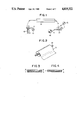
By the electric discharge machining as described above, the coil block 10 is cut into a predetermined number of coils 31 having a predetermined thickness as shown in FIG. 15. FIG. 16A shows the appearance of one of such flat coils 31 after it has been removed from the core shaft 6.
A flat coil 31 obtained in this manner thus includes a rolled up portion 31a of copper foil and insulators, and terminal electrodes 31b and 31c. The flat coil 31 has a very small thickness, and the copper foil 1 is wound or layered very closely. Accordingly, the flat coil 31 is very effective for use as a motor coil.
The inventors have further observed a cut face of a flat coil formed by electric discharge machining with the aid of a microscope. Such observation reveals that, suprisingly the insulator layers 32 composed of the high molecular weight film 2 plus the bonding agent layers 3 and 4 project from the layers of copper foil 1 as shown in FIG. 17, and accordingly, the insulation between adjacent layers of the copper foil 1 is maintained completely.
While the projections of the insulator layers 32 beyond the metal layers may be left as they are, they may optionally be removed by polishing using a lapping device 33 as shown in FIG. 18 in order to assure the accuracy of the width of the flat coil 31.
The flat coil 31 produced by the steps described above may be incorporated into an electric motor after other steps such as masking terminal portions, coating with a resin material, and inspecting for proper inductance, continuity resistance, and insulation testing. The inventors have actually produced a flat motor having a diameter of about 2.7 mm and a thickness of 2 mm using flat coils 31 obtained in accordance with the present invention.
An improvement in the overall structure of the coils will now be described.
Referring to FIG. 16B, a flat coil produced in accordance with the present invention includes a coil section 31a composed of a rolled body of conductor foil and an insulator film wound into a number of convolutions until predetermined characteristics are obtained. A pair of terminals 31b and 31c are located at opposite ends of the innermost and outermost turns of the rolled up body and provide portions for external connections. A metal reinforcing layer 50 covers the outer periphery of the rolled up body. An insulating resin layer 40 is formed by application of a resin material in the form of a belt to a terminal end 31d of the outermost turn of the coil section 31a. In this manner, the terminal end 31d of the coil section 31a is sealed by the insulating resin layer 40.
The metal reinforcing layer 50 is formed by electroplating a portion of the outer periphery of the coil section 31a other than the insulating resin layer 40. The outermost turn of the conductor foil has a total thickness equal to the thickness of the conductor foil itself and the thickness of the metal reinforcing layer 50.
The flat coil with such construction as described above has the improved mechanical strength by the metal reinforcing layer 50 so that it is resistant to deformation and the like. The terminal 31c provided on the outer periphery of the coil section 31a is enclosed by the metal reinforcing layer 50 and is closely contacted with the conductor foil. Accordingly, the connection of the terminal 31b through the conductor foil is assured while the mounting strength of the terminal 31c is increased.
Since the metal reinforcing layer 50 is partly cut and the insulating resin layer 40 is interposed in the cut space in the metal reinforcing layer 50, the metal reinforcing layer itself does not produce an electric loop nor deteriorate the capacity of the coil section 31a.
In producing a flat coil of the type just described, a rolled up body as shown in FIG. 9A is formed in a manner similar to the first embodiment already described. In this case, however, the copper foil must necessarily be exposed on an outer periphery of the rolled up body 7, and accordingly attention must be paid to the winding direction of the layered body 5 as shown in FIG. 2. Further, when bonding agent layers are formed on opposite faces of a high molecular weight film, it is preferable to remove in advance the bonding agent layer only on an outer face near a terminal end of an outermost turn of the high molecular weight film.
As a subsequent step, a solder strip 9 is attached along the terminal edge of the rolled up body 7 so that when the rolled up body 7 is thereafter cut into coils, the solder strip may serve as one lead electrode on each of the coils. The solder strip 9 can readily be formed by extruding solder material in a softened condition from a nozzle 23.
Subsequently, an insulator resin material is applied along the terminal end portion of the outermost turn of the rolled up body 7 to form an insulator resin layer 40 as shown in FIG. 9B. Numerous resin materials can be employed as insulating resin materials 40.
The insulator resin may be a buthyral resin, a phenol resin, an epoxy resin, an urethane resin, or an acrylic acid resin.
Subsequently, a metal reinforcing layer 50 is coated by electrolytic plating of the entire surface of the rolled up body 7 on which the insulating resin layer 40 is provided. The electrolytic plating may be copper plating, nickel plating, zinc plating, chromium plating, solder plating, tin plating or the like.
By means of electrolytic plating, a metal reinforcing layer 50 is formed on a conductor portion of the rolled up body 7 but not on the insulating resin layer 40. Accordingly, the metal reinforcing layer 50 does not form an electric loop.
FIG. 9B is a perspective view showing the appearance of the rolled up body 7 around which the metal reinforcing layer 50 is formed. As seen in this figure, a block 10 includes all the components of the coil including the rolled up body 7, the conductive metal strip 8 which is to later provide one electrode, and the solder strip 9 which is to make the other electrode of the coil, the insulating resin layer 40, and the metal reinforcing layer 50. This block 10 is hereafter referred to as a coil block.
Similarly to the steps described in the first embodiment, the coil block 10 is placed in juxtaposition to an electrode as shown in FIG. 14E and cut into flat coils having a predetermined thickness by electric discharge machining. Since the coil block 10 has a metal reinforcing layer 50 formed thereon, the machining conditions can be made severe and the entire cutting speed can be increased. The cutting speed is largely influenced by the speed upon starting of cutting, and from this point of view, the provision of the metal reinforcing layer 50 is very effective. Since the mechanical strength at the outer periphery of the coil is increased by the formation of the metal reinforcing layer 50, even when a very thin copper foil which can not be cut by conventional means is employed, the coil block 10 can be cut and deformation of the coils after cutting of the coil block 10 can be minimized.
The inventors have produced flat coils under the following conditions and have confirmed improvements in cutting time and in yield rate.
In particular, a bonding agent was first coated with a thickness of about 5 microns after drying on a copper foil having a thickness of 35 microns. The ribbon of the bonding agent coated copper foil was wound into a rolled up body as shown in FIG. 9A.
Subsequently, a resin composition having the following formulation was applied in the form of a belt to a terminal end portion of an outermost turn of the rolled up body. The thickness of the applied layer was 35 microns.
______________________________________                                    
Component        Parts by Weight                                          
______________________________________                                    
Butyral resin    100                                                      
(S-LEC BX-1, from                                                         
Sekisui Kagaku K.K.                                                       
Phenolic resin    60                                                      
(PR50838 from                                                             
Sumitomo Durez Co.                                                        
Ethyl alcohol    150                                                      
Toluene          330                                                      
Acetone          120                                                      
______________________________________                                    
The resin composition shown above had a solids content of 20%. The rolled up body with the resin composition applied thereto was put into a copper pyrophosphoric acid plating tank, and electrolytic plating was effected. The plating conditions included a current density of 3 A/dm2 ; a plating time of 60 minutes; and a plating thickness of 45 microns. A coil block as shown in FIG. 9B was obtained.
This coil block plated as described above was cut by electric discharge machining to produce flat coils. The cutting time and the yield rate were compared with those of flat coils produced without plating. The results are shown in the Table below:
______________________________________                                    
            Cutting Time                                                  
                     Yield Rate                                           
______________________________________                                    
Plated        31.03 seconds                                               
                         67%                                              
Not Plated    49.98 seconds                                               
                         34%                                              
______________________________________                                    
As seen from the Table, cutting time was improved by about 38% while the yield rate was improved by about 30%. It was found possible to cut the resin composition layers without difficulty.
As apparent from their foregoing description, the cutting of the rolled up body by electric discharge machining to form separate coils can be produced conveniently by mass production.
The insulation between adjacent layers of the wound metal foil is completely effective, so there is little chance of any short-circuiting appearing on the products. Thus, flat coils having a high reliability can be produced.
A flat coil produced by the process of the present invention and having a metal reinforcing layer on an outer periphery thereof has improved mechanical strength so that deformation is not a significant problem.
Due to the presence of the metal reinforcing layer, the terminals for external connection can be attached in a stabilized condition to the flat coil, and the terminals themselves can be improved in strength.
Due to the presence of an insulating resin layer intermediate the metal reinforcing layer, the metal reinforcing layer will not form an electric loop at all and so the capacity of the coil is not deteriorated.
Since the rolled up body of conductor foil is cut by an electric discharge machining after a metal reinforcing layer has been formed on an outer peripheral portion by metal plating, even when very thin copper foil which cannot be cut by conventional cutting means is employed, a good cutting can be assured and the cutting speed can be improved. In addition, the process is a very simple process which does not require a special technique or high accuracy so that the process of the invention is very high in practical value.
Having fully described the invention, it will be apparent to those having ordinary skill in the art that changes and modifications can be made thereto without departing from the scope and spirit of the present invention as set forth herein.

Claims (11)

We claim as our invention:
1. A process for producing a flat coil, comprising the steps of;
forming an insulator layer on a ribbon of metal foil,
winding said ribbon and said insulator layer about a center shaft while pressing the insulator layer toward said center shaft to form a rolled up metal foil body, and
cutting the rolled up body in a direction transverse to the axis of said center shaft by electric discharge machining into individual flat coils of a predetermined thickness.
2. A process according to claim 1 wherein said rolled up metal foil body is cut by electric discharge machining while it is immersed in a coolant and electrically connected with a liquid electrical conductor in a vessel having a grounded connection.
3. A process according to claim 2 wherein said liquid electrical conductor is mercury.
4. A process according to claim 1 wherein said electric discharge machining is carried out with a pulse current.
5. A process for producing a flat coil comprising the steps of:
forming an insulator layer on a ribbon of metal foil,
winding the metal foil and the insulator layer about a center shaft while pressing said insulator layer toward said center shaft to form a rolled up body of metal foil and insulator,
attaching an electrically conductive strip integrally at least to the inner or outer periphery of the rolled up body over the entire width thereof to form a coil block, and
cutting the coil block into individual flat coils of predetermined thickness by electric discharge machining.
6. A process for producing a flat coil comprising the steps of:
forming an insulator layer on a ribbon of metal foil,
winding said ribbon and its insulator layer attached around a center shaft while pressing the insulator layer toward the center shaft to form a rolled up body of metal foil,
attaching an electrically conductive metal terminal strip to at least the inner or outer periphery of the rolled up body over the entire width of said rolled up body,
forming an insulating resin layer at a terminal end portion of said outermost turn of said rolled up body,
coating the outer periphery of said rolled up body other than said insulating resin layer with an electroplated metal reinforcing layer to form a coil block, and
cutting the coil block in a direction transverse to said center shaft into flat coils of a predetermined thickness by electric discharge machining.
7. A process according to claim 6 wherein said coil block is cut by electric discharge machining while it is entirely immersed in a coolant and is electrically in contact with a liquid conductor in a grounded vessel.
8. A process according to claim 7 wherein said liquid conductor is mercury.
9. A process according to claim 6 wherein said electric discharge machining is carried out with a pulse current.
10. A process according to claim 6 wherein said rolled up body is formed by winding said metal foil and said insulator film about a shaft having a polygonal cross section.
11. A process according to claim 6 which includes the step of positioning a plurality of said coil blocks in parallel relationship with each other and cutting said blocks by electric discharge machining by means of a plurality of discharge electrodes in a predetermined spaced relationship in a direction transverse to said coil blocks.
US07/058,560 1986-06-08 1987-06-05 Method for manufacturing a flat coil Expired - Fee Related US4819322A (en)

Applications Claiming Priority (4)

Application Number Priority Date Filing Date Title
JP61132513A JPS62290116A (en) 1986-06-08 1986-06-08 Manufacture of flat coil
JP61-132513 1986-06-08
JP62022028A JPS63188906A (en) 1987-02-02 1987-02-02 Flat coil and its manufacture
JP62-22028 1987-02-02

Publications (1)

Publication Number Publication Date
US4819322A true US4819322A (en) 1989-04-11

Family

ID=26359186

Family Applications (1)

Application Number Title Priority Date Filing Date
US07/058,560 Expired - Fee Related US4819322A (en) 1986-06-08 1987-06-05 Method for manufacturing a flat coil

Country Status (5)

Country Link
US (1) US4819322A (en)
KR (1) KR960005687B1 (en)
CN (1) CN1009598B (en)
DE (1) DE3719229A1 (en)
GB (1) GB2191427B (en)

Cited By (10)

* Cited by examiner, † Cited by third party
Publication number Priority date Publication date Assignee Title
US5160820A (en) * 1990-03-30 1992-11-03 Honda Giken Kogyo Kabushiki Kaisha Welding transformer and method of manufacturing same
US5351389A (en) * 1991-01-07 1994-10-04 Amei Technologies Inc. Method for fabricating a contoured triangular transducer system
US5628861A (en) * 1995-01-25 1997-05-13 Abb Power T&D Company Inc. Method for adhesively bonded laminate for use in an electrical apparatus such as a transformer, generator, or motor
US5866965A (en) * 1991-06-27 1999-02-02 Dana Corporation Variable reluctance motor having foil wire wound coils
WO2002049050A1 (en) 2000-12-11 2002-06-20 Koninklijke Philips Electronics N.V. Band coil
US6686822B2 (en) * 2000-04-19 2004-02-03 General Electric Company Powder coated generator field coils and related method
US20050038613A1 (en) * 2002-05-23 2005-02-17 Oht Inc. Apparatus and method for inspecting electrical continuity of circuit board, jig for use therein, and recording medium thereon
WO2009109321A1 (en) * 2008-03-06 2009-09-11 Abb Technology Ag Winding conductor
US11004602B2 (en) * 2017-10-18 2021-05-11 Goertek Inc. Manufacturing method of flat coil and electronic apparatus
US11605496B2 (en) * 2018-04-09 2023-03-14 Abb Schweiz Ag Foil wound magnetic assemblies with thermally conductive tape and methods of assembling same

Families Citing this family (8)

* Cited by examiner, † Cited by third party
Publication number Priority date Publication date Assignee Title
DE19940090A1 (en) * 1999-08-24 2001-03-01 Georg Siegel Gmbh Zur Verwertu Coil manufacturing method e.g. for security labels, involves use of insulating foil coated with metallic conductor and wound around shape-determining bobbin
CN1906830B (en) * 2004-01-16 2010-05-05 张金铭 Coil, its application and dedicated device for making coil
WO2005074107A1 (en) * 2004-01-16 2005-08-11 Jinming Zhang A coil, its application and its special manufacture equipment
CN102172802A (en) * 2011-01-17 2011-09-07 西南铝业(集团)有限责任公司 Metal plate strip material and coiled material interlayer fixing method
CN103762071A (en) * 2013-12-31 2014-04-30 江苏有能电力自动化有限公司 Foil type capacitive coil sintering process
WO2019086199A1 (en) * 2017-11-06 2019-05-09 Asml Holding N.V. Truncated flat wire coil
CN108987094A (en) * 2018-06-20 2018-12-11 深圳市信维通信股份有限公司 The production method of Wireless charging coil
CN115378205B (en) * 2022-05-09 2023-05-05 哈尔滨理工大学 Manufacturing method of new energy automobile motor stator flat wire winding transposition structure

Citations (7)

* Cited by examiner, † Cited by third party
Publication number Priority date Publication date Assignee Title
GB806452A (en) * 1953-12-30 1958-12-23 Sylvania Electric Prod Improvements in methods of making electromagnetic coils
US2998583A (en) * 1956-02-13 1961-08-29 Willis G Worcester Electrical apparatus and electromagnetic coils and method of making the same
US3112556A (en) * 1954-12-24 1963-12-03 Sylvania Electric Prod Method of manufacturing electrical coils
US3202592A (en) * 1960-08-03 1965-08-24 Syncro Corp Inductance-capacitance device and method of manufacture
US3225269A (en) * 1955-01-03 1965-12-21 Willis G Worcester Electrical apparatus
GB1462109A (en) * 1973-05-04 1977-01-19 Dainippon Printing Co Ltd Fabrication of coils
US4495038A (en) * 1981-08-12 1985-01-22 Inoue-Japax Research Incorporated Method of and apparatus for electroerosively wire-cutting a conductive workpiece

Patent Citations (7)

* Cited by examiner, † Cited by third party
Publication number Priority date Publication date Assignee Title
GB806452A (en) * 1953-12-30 1958-12-23 Sylvania Electric Prod Improvements in methods of making electromagnetic coils
US3112556A (en) * 1954-12-24 1963-12-03 Sylvania Electric Prod Method of manufacturing electrical coils
US3225269A (en) * 1955-01-03 1965-12-21 Willis G Worcester Electrical apparatus
US2998583A (en) * 1956-02-13 1961-08-29 Willis G Worcester Electrical apparatus and electromagnetic coils and method of making the same
US3202592A (en) * 1960-08-03 1965-08-24 Syncro Corp Inductance-capacitance device and method of manufacture
GB1462109A (en) * 1973-05-04 1977-01-19 Dainippon Printing Co Ltd Fabrication of coils
US4495038A (en) * 1981-08-12 1985-01-22 Inoue-Japax Research Incorporated Method of and apparatus for electroerosively wire-cutting a conductive workpiece

Cited By (16)

* Cited by examiner, † Cited by third party
Publication number Priority date Publication date Assignee Title
US5160820A (en) * 1990-03-30 1992-11-03 Honda Giken Kogyo Kabushiki Kaisha Welding transformer and method of manufacturing same
US5351389A (en) * 1991-01-07 1994-10-04 Amei Technologies Inc. Method for fabricating a contoured triangular transducer system
US5401233A (en) * 1991-01-07 1995-03-28 Amei Technologies Inc. Contoured triangular transducer system for PEMF therapy
US5866965A (en) * 1991-06-27 1999-02-02 Dana Corporation Variable reluctance motor having foil wire wound coils
US5628861A (en) * 1995-01-25 1997-05-13 Abb Power T&D Company Inc. Method for adhesively bonded laminate for use in an electrical apparatus such as a transformer, generator, or motor
US5817209A (en) * 1995-01-25 1998-10-06 Abb Power T&D Company Inc. Adhesive bording system for bonding laminae to form a laminate
US6686822B2 (en) * 2000-04-19 2004-02-03 General Electric Company Powder coated generator field coils and related method
US20020079775A1 (en) * 2000-12-11 2002-06-27 Janssen Henricus Wilhelmus Aloysius Band coil
WO2002049050A1 (en) 2000-12-11 2002-06-20 Koninklijke Philips Electronics N.V. Band coil
US6926588B2 (en) * 2000-12-11 2005-08-09 Koninklijke Philips Electronics N.V. Band coil
US20050236923A1 (en) * 2000-12-11 2005-10-27 Janssen Henricus W A Band coil
US20050038613A1 (en) * 2002-05-23 2005-02-17 Oht Inc. Apparatus and method for inspecting electrical continuity of circuit board, jig for use therein, and recording medium thereon
US6947853B2 (en) * 2002-05-23 2005-09-20 Oht, Inc. Apparatus and method for inspecting electrical continuity of circuit board, jig for use therein, and recording medium thereon
WO2009109321A1 (en) * 2008-03-06 2009-09-11 Abb Technology Ag Winding conductor
US11004602B2 (en) * 2017-10-18 2021-05-11 Goertek Inc. Manufacturing method of flat coil and electronic apparatus
US11605496B2 (en) * 2018-04-09 2023-03-14 Abb Schweiz Ag Foil wound magnetic assemblies with thermally conductive tape and methods of assembling same

Also Published As

Publication number Publication date
GB8713114D0 (en) 1987-07-08
KR880000156A (en) 1988-03-23
GB2191427A (en) 1987-12-16
CN1009598B (en) 1990-09-12
KR960005687B1 (en) 1996-04-30
CN87104150A (en) 1988-02-24
DE3719229A1 (en) 1987-12-10
GB2191427B (en) 1990-03-28

Similar Documents

Publication Publication Date Title
US4819322A (en) Method for manufacturing a flat coil
US3921041A (en) Dual capacitor
US6449830B1 (en) Method of manufacturing wire wound electronic component
US7572980B2 (en) Copper conductor with anodized aluminum dielectric layer
US3857074A (en) Electrical capacitors and method of making same
US20230245815A1 (en) Coil component
US3906297A (en) Metallized film capacitor and method of manufacture thereof
US7477126B2 (en) Winding for a transformer or a coil and method for the production thereof
US20020151114A1 (en) Method of manufacturing chip inductor
US3719911A (en) Laminated magnetic coil materials
JP4482295B2 (en) Manufacturing method of coil for electric equipment
JPS63220734A (en) Flat coil
CN109961920B (en) Wound inductor and method of manufacturing the same
US5119058A (en) Laminated conductor for high current coils
JP3110160B2 (en) Manufacturing method of anisotropic conductive film
JPS63188906A (en) Flat coil and its manufacture
JPS63220735A (en) Flat coil
JPH0574624A (en) Coil
JPS637608A (en) Manufacture of flat coil
JPH05292692A (en) Thin film coil for micro-motor and manufacture thereof
US3509610A (en) Method of manufacturing capacitors
KR19980042442A (en) Coil-type Electronic Components and Manufacturing Method Thereof
JP2023150716A (en) Method of manufacturing electronic component
JP2023150409A (en) Electronic component, and method of manufacturing the same
JP3502439B2 (en) Method of manufacturing resin-molded electromagnetic device

Legal Events

Date Code Title Description
AS Assignment

Owner name: SONY CORPORATION,JAPAN

Free format text: ASSIGNMENT OF ASSIGNORS INTEREST;ASSIGNORS:HIGUCHI, SHIGETAKA;NOGUCHI, ISAO;KURITA, SHUJI;AND OTHERS;SIGNING DATES FROM 19870601 TO 19870603;REEL/FRAME:004760/0890

Owner name: SONY CORPORATION, 7-35 KITASHINAGAWA-6, SHINAGAWA-

Free format text: ASSIGNMENT OF ASSIGNORS INTEREST.;ASSIGNORS:HIGUCHI, SHIGETAKA;NOGUCHI, ISAO;KURITA, SHUJI;AND OTHERS;REEL/FRAME:004760/0890;SIGNING DATES FROM 19870601 TO 19870603

FEPP Fee payment procedure

Free format text: PAYOR NUMBER ASSIGNED (ORIGINAL EVENT CODE: ASPN); ENTITY STATUS OF PATENT OWNER: LARGE ENTITY

FPAY Fee payment

Year of fee payment: 4

REMI Maintenance fee reminder mailed
LAPS Lapse for failure to pay maintenance fees
FP Lapsed due to failure to pay maintenance fee

Effective date: 19970416

STCH Information on status: patent discontinuation

Free format text: PATENT EXPIRED DUE TO NONPAYMENT OF MAINTENANCE FEES UNDER 37 CFR 1.362