US4822571A - Metering mechanism for a swimming pool chemical dispenser - Google Patents
Metering mechanism for a swimming pool chemical dispenser Download PDFInfo
- Publication number
- US4822571A US4822571A US07/104,287 US10428787A US4822571A US 4822571 A US4822571 A US 4822571A US 10428787 A US10428787 A US 10428787A US 4822571 A US4822571 A US 4822571A
- Authority
- US
- United States
- Prior art keywords
- metering valve
- valve body
- float
- cap
- longitudinally extending
- Prior art date
- Legal status (The legal status is an assumption and is not a legal conclusion. Google has not performed a legal analysis and makes no representation as to the accuracy of the status listed.)
- Expired - Lifetime
Links
Images


Classifications
-
- C—CHEMISTRY; METALLURGY
- C02—TREATMENT OF WATER, WASTE WATER, SEWAGE, OR SLUDGE
- C02F—TREATMENT OF WATER, WASTE WATER, SEWAGE, OR SLUDGE
- C02F1/00—Treatment of water, waste water, or sewage
- C02F1/68—Treatment of water, waste water, or sewage by addition of specified substances, e.g. trace elements, for ameliorating potable water
- C02F1/685—Devices for dosing the additives
- C02F1/688—Devices in which the water progressively dissolves a solid compound
-
- B—PERFORMING OPERATIONS; TRANSPORTING
- B01—PHYSICAL OR CHEMICAL PROCESSES OR APPARATUS IN GENERAL
- B01F—MIXING, e.g. DISSOLVING, EMULSIFYING OR DISPERSING
- B01F21/00—Dissolving
- B01F21/20—Dissolving using flow mixing
- B01F21/22—Dissolving using flow mixing using additional holders in conduits, containers or pools for keeping the solid material in place, e.g. supports or receptacles
-
- C—CHEMISTRY; METALLURGY
- C02—TREATMENT OF WATER, WASTE WATER, SEWAGE, OR SLUDGE
- C02F—TREATMENT OF WATER, WASTE WATER, SEWAGE, OR SLUDGE
- C02F2103/00—Nature of the water, waste water, sewage or sludge to be treated
- C02F2103/42—Nature of the water, waste water, sewage or sludge to be treated from bathing facilities, e.g. swimming pools
-
- Y—GENERAL TAGGING OF NEW TECHNOLOGICAL DEVELOPMENTS; GENERAL TAGGING OF CROSS-SECTIONAL TECHNOLOGIES SPANNING OVER SEVERAL SECTIONS OF THE IPC; TECHNICAL SUBJECTS COVERED BY FORMER USPC CROSS-REFERENCE ART COLLECTIONS [XRACs] AND DIGESTS
- Y10—TECHNICAL SUBJECTS COVERED BY FORMER USPC
- Y10T—TECHNICAL SUBJECTS COVERED BY FORMER US CLASSIFICATION
- Y10T137/00—Fluid handling
- Y10T137/4891—With holder for solid, flaky or pulverized material to be dissolved or entrained
Definitions
- the device which includes the present invention is also the subject of four additional concurrently filed applications for letters patent, which are all assigned to the assignee of the present invention.
- the four additional applications are U.S. Ser. No. 104,501, entitled “Swimming Pool Chemical Dispenser and Method of Making Same," U.S. Ser. No. 104,291, entitled “Childproof Top for a swimming Pool Chemical Dispenser,” U.S. Ser. No. 104,290, entitled “Chemical Depletion Signal for a swimming Pool Chemical Dispenser,” and U.S. Ser. No. 104,402, entitled “Swimming Pool Chemical Dispenser With Restraining Tether.”
- the additional four applications are hereby incorporated herein by reference.
- the present invention relates generally to devices for dispensing chemicals into swimming pools to maintain the quality and clarity of water therein, and more particularly to a floating dispenser of novel construction for containing solid chemical pellets or tablets therein which are dispensed essentially continuously by nature of dissolution of the solid pellets or tablets by water flowing through the floating dispenser.
- Untreated water in both above-ground and below-ground swimming pools tends to deteriorate relatively rapidly due to the growth of bacteria and other organic matter such as algae which result in untreated water quickly becoming both unsanitary and unclear.
- the pool water remains untreated for several days, it represents a health hazard to swimmers, and a cleanup problem due to the growth of algae on the surface of the pool.
- Water soluble chemicals are added to the pool water to kill the bacteria and to retard the growth of algae.
- chlorine is the chemical used to maintain water quality, with the periodic administration of a dose of a liquid solution containing chlorine being the most commonly used treatment.
- the chlorine level of the water in the pool will therefore vary considerably during the course of even one day, with the chlorine concentration being higher than desirable immediately after the administration of liquid chlorine, and lower than desirable after the chlorine has partially dissipated over a period of time. This diminution of chlorine concentration may vary considerably due to the size and temperature of the pool, the weather, and the amount of use the pool is experiencing as well as other factors.
- trichloroisocyanurates which are generally referred to as trichlor.
- trichloroisocyanurates may last as long as one to two weeks, and they leave no residue after dissolving. Although they have the advantage of leaving no residue, they dissolve relatively quickly and therefore only tablets may be used, since pellets would not last for even a week.
- Calcium hypochlorite Another type of solid pool disinfectant chemical in use is calcium hypochlorite, which is relatively inexpensive and convenient to use. Calcium hypochlorite tablets last for an extended length of time, such as for example two weeks or more in a floating or skimmer feeder. The disadvantage of calcium hypochlorite pellets is that they leave a residue in the floating feeder or on the bottom of the pool after dissolving. Calcium hypochlorite is used mainly for infrequent shock treatments for this reason.
- skimmer feeders are shown in U.S. Pat. Nos. 4,546,503, to Casberg, and in 4,643,881, to Alexander et al. Such feeders are used in forced circulation flow pool systems having a skimmer basket at the location at which water is removed from the pool.
- the feeder has solid chemical tablets or pellets (referred to hereafter generically as "chlorine tablets") placed inside, and the feeder is placed in the skimmer basket. Chlorine is added to the water as it is drawn out of the pool for filtering and heating. Skimmer feeders are frequently used in large and frequently used pools, such as for example in hotel pools.
- Floating feeders are buoyant devices, generally molded of plastic and designed for carrying solid tablets or pellets below the water surface while the device is floating. By either varying the area through which water may flow through the feeder, or by varying the amount of chlorine tablets placed in the feeder, or both, the flow rate of chlorine into the pool water is controlled. The area through which water may flow is usually set by adjusting the area of apertures in the lower sides of the floating feeders. Floating feeders are relatively inexpensive and easy to use, and as such have found particular favor in the home pool market.
- Most feeders use a similar type of metering mechanism for selecting the size of the apertures through which water flows into and out of the feeder, and hence the dispersion rate of chlorine into the pool water.
- This preferred metering mechanism uses a first piece having a plurality of apertures therethrough, which apertures represent the maximum size aperture of the device.
- a second piece which is typically rotatable with respect to said first piece allows the apertures to be selectively, partially closed to select the amount of water which may flow through the portion of the device containing the chlorine tablets. In this way the dispersion rate of the chlorine into the water may be controlled.
- Such floating feeders work reasonably well, but due to their metering design they are susceptible to undesirable changes in the rate of chlorine dispersion due to inadvertent changes in the size of the apertures through which water flows.
- inadvertent changes are usually caused by the feeder being bumped, either by swimmers in the pool or by the feeder being thrown into the edge of the pool by waves in the pool.
- the metering mechanism Upon being bumped the metering mechanism will be unable to resist relative motion between the first and second pieces, causing the size of the apertures to be increased or decreased. It is apparent that it is undesirable to allow such an ordinary and frequently occurring situation to change the rate of chlorine dispersal. Accordingly, it is an objective of the present invention to provide a metering mechanism which will not be changed by bumping of the feeder, however severe.
- the aforesaid objectives must be accomplished by a design which both effective and easily and inexpensively manufactured.
- the improved metering mechanism must use snap-together assembly.
- the improved feeder mechanism must also have excellent strength and durability characteristics to ensure a long life.
- the resulting feeder metering mechanism must therefore be adjustable over a wide range of dispersion rates, while remaining easy and quick to adjust. It must be completely resistant to changes in the dispersion rate caused by the feeder being bumped.
- the metering mechanism design must also be inexpensive to implement, while providing greater strength and durability than previous designs. Finaly, the aforesaid advantages and objectives must all be attained while incurring no relative disadvantage.
- a floating feeder incorporating five main molded segments is taught, two of which segments comprise the feeder metering mechanism.
- the general configuration of the floating feeder has the advantages of being manufacturable using only simple molds, of having components locked to each other to prevent undesirable rotation therebetween, and having a snap together assembly of all components save the assembly of the float assembly, which must be waterproof.
- This general configuration is the subject of the above-referenced patent application entitled “Swimming Pool Chemical Dispenser and Method of Making Same.”
- the float assembly is manufactured in two segments- a top half and a bottom half.
- the two halves of the float are configured to allow them to be attached together to form a watertight assembly, preferably by the use of adhesive means.
- Mounted below the float assembly is the metering valve assembly, the design of which metering valve comprises the present invention.
- the metering valve assembly is made up of two components- a metering valve body and a metering valve cap.
- the metering valve body is attached to the bottom of the float assembly by inserting the top of the metering valve into the bottom of the float assembly.
- a snap fit is used to retain the top of the metering valve body in the bottom of the float assembly.
- the metering valve body is essentially formed by two cylindrical segments, the top one of which cylinders is of slightly larger diameter than the bottom cylinder.
- the top of the top cylinder is the portion of the metering valve body which is inserted into and retained in the bottom float.
- the upper portion of the bottom cylinder has a plurality of longitudinally extending ribs with apertures therebetween, the top ends of which ribs are attached to the bottom of the top cylinder.
- the plurality of apertures are to allow water to flow therethrough to contact chlorine tablets which will be placed in the device.
- the lower portion of the bottom cylinder has threads around the outer surface thereof.
- a tapered shoulder is located circumferentially around the bottom cylinder of the metering valve body intermediate the ribs and the threads.
- the metering valve cap is designed to fit over the metering valve body.
- the metering valve cap is essentially cylindrical and the size of the top cylinder of the metering valve body.
- the bottom side of the metering valve cap is closed to seal the bottom of the metering valve assembly, so that chlorine tablets placed in the device will rest on the bottom of the metering valve assembly.
- At the top of the metering valve cap is a shoulder extending slightly inwardly, and inside the metering valve cap and towards the bottom thereof are located threads.
- the open top of the metering valve cap is placed over the bottom of the metering valve body, until the shoulder on the metering valve cap is forced past the threads and over the shoulder on the metering valve body. At this point the threads in the metering valve cap contact the threads on the bottom cylinder of the metering valve body, and the apertures between the ribs on the metering valve body are completely open. The metering valve cap may then be moved turned to move it longitudinally on the metering valve body, thereby selectively closing the apertures in the metering valve body to the degree desired. It will be appreciated that the shoulders on the metering valve body and the metering valve cap cooperate to prevent the cap from inadvertently coming completely off the metering valve body when the metering valve cap is unscrewed.
- the float has an aperture in the top thereof through which chlorine tablets may be placed in the device.
- the aperture is sealed with a float cap which mounts into the aperture to seal it from the top side. Relative movement between the float cap and the float assembly is also inhibited by the interlocking design of the float cap and the float assembly, which is the subject of the above-identified copending patent application entitled "Childproof Top for a swimming Pool Chemical Dispenser.”
- the present invention teaches a metering valve for a floating feeder which is precisely adjustable and yet easily and inexpensively manufactured, particularly since the metering valve parts may be made using simple rather than complex molds and snap together without requiring fasteners.
- the improved feeder mechanism also has excellent strength and durability characteristics to ensure a long life.
- FIG. 1 is a plan view from the top side of the float top illustrating the narrow and wide beads used to retain the float cap, and also showing the cord retainer recess;
- FIG. 2 is a sectional view of the float top of FIG. 1 illustrating the float top inner and outer cylinders used to form the top half of a sealed float compartment, and also showing the cord retainer recess;
- FIG. 3 is an enlarged portion of the sectional view of the float top in FIG. 2 showing the tongue located on the bottom side of the float top inner cylinder;
- FIG. 4 is an enlarged cutaway view of a portion of the float top shown in FIG. 1 showing one of the narrow beads located inside the float top inner cylinder and near to the top side thereof;
- FIG. 5 is an enlarged cutaway view of a portion of the float top shown in FIG. 1 showing one of the wide beads located inside the float top inner cylinder and near to the top side thereof;
- FIG. 6 is a plan view from the bottom side of the float bottom showing the shoulder and three tabs used to secure the metering valve body to the float assembly;
- FIG. 7 is a sectional view of the float bottom shown in FIG. 1 illustrating the float bottom inner and outer cylinders used to form the bottom half of the sealed float compartment, and also showing the shoulder and one of the tabs used to secure the metering valve body;
- FIG. 8 is an enlarged view of a portion of the float bottom as shown in FIG. 6, showing a portion of the shoulder and one of the tabs used to secure the metering valve body;
- FIG. 9 is an enlarged view of a portion of the float bottom as shown in FIG. 7, showing a portion of the shoulder and one of the tabs used to secure the metering valve body;
- FIG. 10 an enlarged portion of the sectional view of the float bottom in FIG. 7, showing the groove located on the top side of the float bottom inner cylinder;
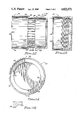
- FIG. 11 is a plan view from the top of the metering valve body of the present invention showing the three notches for placement around the three tabs on the float bottom of FIG. 6, and also showing from the top the configuration of the metering valve ribs and the apertures formed therebetween;
- FIG. 12 is a sectional view of the metering valve body shown in FIG. 11, showing the configuration of the metering valve ribs of the present invention and the apertures formed therebetween, the shoulder used to retain the metering valve cap on the metering valve body, and the threads on the outside of the lower portion of the metering valve body lower cylinder;
- FIG. 13 is an enlarged view from the side of the metering valve wide rib of the present invention which contains the position markings used to indicate the degree to which the apertures located between the metering valve ribs are opened or closed by the metering valve cap;
- FIG. 14 is a plan view from the top side of the metering valve cap of the present invention showing the location of the two tabs used in the present invention to prevent inadvertent relative movement between the metering valve cap and the metering valve body;
- FIG. 15 is a sectional view of the metering valve cap shown in FIG. 14, showing the threads on the inside of the lower portion of the metering valve cap;
- FIG. 16 is an enlarged cutaway view of a portion of the metering valve cap of FIG. 15, showing the configuration of one of the two tabs of the present invention used to prevent inadvertent relative movement between the metering valve cap and the metering valve body;
- FIG. 17 is a plan view from the top side of the float cap used to close the aperture in the top of the float top;
- FIG. 18 is a plan view from the bottom of the float cap shown in FIG. 17, illustrating the location of the narrow and wide beads on the bottom of the float cap which are for engagement of the narrow and wide beads in the float top;
- FIG. 19 is a sectional view of the float cap shown in FIGS. 17 and 18, showing the portion used to grip the float cap;
- FIG. 20 is a view from the side of the cord retainer used to retain one end of the tethering cord to the float top;
- FIG. 21 is a view from the side of the retainer hook used to retain the other end of the tethering cord to the side of a swimming pool;
- FIG. 22 is a side view of the assembled floating dispenser of the present invention partially cut away to show details of assembly.
- the preferred embodiment of the present invention uses a number of parts, the construction of which parts will be discussed first before discussing the operation of the device.
- the float assembly is made of two parts, the first of which is a float top 30 which is shown in FIGS. 1 and 2.
- the float top 30 forms the top half of a sealed area which will be used to provide buoyancy to the feeder. This top half of the sealed area is located between a float top outer cylinder 32 and a float top inner cylinder 34.
- tops of the float top outer cylinder 32 and the float top inner cylinder 34 are both sealingly connected to a the top surface 36 extending therebetween, which top surface 36 is shown in the figures to be flat adjacent the float top inner cylinder 34 and angled slightly for aesthetic effect near the float top outer cylinder 32.
- the area inside the float top inner cylinder 34 is open, both at the top and at the bottom thereof.
- Located circumferentially around the inside surface of the float top inner cylinder 34 at a location near to the top of the float top inner cylinder 34 are an end-to-end series of four raised beads. Two of the beads are wide beads 38 and 40, and two of the beads are narrow beads 42 and 44.
- the wide bead 38 is located intermediate the narrow bead 42 and the narrow bead 44
- the narrow bead 42 is located intermediate the wide bead 38 and the wide bead 40
- the wide bead 40 is located intermediate the narrow bead 42 and the narrow bead 44
- the narrow bead 44 is located intermediate the wide bead 40 and the wide bead 38.
- the narrow bead 44 is shown in cross-section in FIG. 4, and the wide bead 40 is shown in cross-section in FIG. 5.
- the wide bead 38 is identical to the wide bead 40, and the narrow bead 42 is identical to the narrow bead 44.
- the wide beads 38 and 40 have the same height in cross section as the narrow beads 42 and 44, but the wide beads 38 and 40 project further inwardly from the float top inner cylinder 34 than do the narrow beads 42 and 44. In the preferred embodiment, the wide beads 38 and 40 project inwardly from the float top inner cylinder 34 approximately four times as far as do the narrow beads 42 and 44. As a matter of practicality, the wide beads 38 and 40 should project inwardly at least twice as far as do the wide beads 40 and 42.
- each of the narrow beads 42 and 44 extend around the interior of the float top inner cylinder 34 for slightly more than ninety degrees and each of the wide beads 38 and 40 extend around the float top inner cylinder 34 for slightly less than ninety degrees.
- each of the narrow beads 42 and 44 extend around the interior of the float top inner cylinder 34 for ninety-three degrees, and each of the wide beads 38 and 40 extend around the float top inner cylinder 34 for eighty-seven degrees.
- a cord retainer recess 46 Disposed in the top surface 36 of the float top 30 is a cord retainer recess 46.
- the cord retainer recess 46 has disposed below the plane of the top surface 36 a reduced diameter shoulder 48, and but for the presence of the reduced diameter shoulder 48 the cord retainer recess 46 would be an essentially cylindrical recess with the bottom sealed. That the bottom of the cord retainer recess 46 is sealed is essential to the watertight construction of the float assembly, of which the top half is formed between the float top outer cylinder 32 and the float top inner cylinder 34, and under the top surface 36.
- the bottom edge of the float top outer cylinder 32 has extending downwardly therefrom an essentially cylindrical tongue 50 narrower than the thickness of the float top outer cylinder 32.
- the bottom edge of the float top inner cylinder 34 has extending downwardly therefrom an essentially cylindrical tongue 52 narrower than the thickness of the float top inner cylinder 34.
- the cylindrical tongue 52 is shown in detail in FIG. 3, and the cylindrical tongue 50 is identical in cross-sectional configuration to the cylindrical tongue 52. In the preferred embodiment the cylindrical tongues 50 and 52 are slightly tapered approaching the bottoms thereof.
- the cylindrical tongue 52 has extending downwardly therefrom a raised bead 54, which is small compared to the width of the cylindrical tongue 52.
- the cylindrical tongue 50 also has a raised bead 56 (not shown), which is small compared to the width of the cylindrical tongue 50.
- the purposes of the cylindrical tongues 50 and 52 and the raised beads 54 and 56 will becme evident later in conjunction with the discussion of the assembly of the float assembly.
- a float bottom 60 is illustrated which will form the bottom half of the float assembly.
- the float bottom 60 forms the bottom half of the sealed area which will be used to provide buoyancy to the feeder.
- This bottom half of the sealed area is located between a short float bottom outer cylinder 62 and a longer float bottom inner cylinder 64.
- the top of the float bottom outer cylinder 62 and the top of the float bottom inner cylinder 64 extend to the same height, with the bottom of the float bottom inner cylinder 64 extending downward further than does the bottom of the float bottom outer cylinder 62.
- the bottoms of the float bottom outer cylinder 62 and the float bottom inner cylinder 64 are both sealingly connected to an angled bottom surface 66 extending therebetween.
- a shoulder 68 protrudes slightly inwardly from the float bottom inner cylinder 64 at the bottom side thereof. It will be perceived that the area inside the float bottom inner cylinder 64 is open at the top thereof, and inside the shoulder 68 at the bottom thereof.
- Located near to the bottom of the float bottom inner cylinder 64 are three tabs 70, 72, and 74 which are located at one-hundred-twenty degree increments around the inner circumference of the float bottom inner cylinder 64 and the shoulder 68.
- the tab 70 is shown in FIG. 8 to present an essentially square cross-section inside the inner diameter of the shoulder 68, and to have a rounded surface at the bottom end of the tab 70 near to the bottom edge of the float bottom 60 as shown in FIG. 9.
- the tabs 72 and 74 are identical in configuration to the tab 70.
- the top edge of the float bottom outer cylinder 62 has located therein a cylindrical groove 76 which is narrower than the thickness of the float bottom outer cylinder 62.
- the top edge of the float bottom inner cylinder 64 has located therein a cylindrical groove 78 which is narrower than the thickness of the float bottom inner cylinder 64.
- the cylindrical groove 78 is shown in detail in FIG. 10, and the cylindrical groove 76 is identical in cross-sectional configuration to the cylindrical groove 78. In the preferred embodiments, the cylindrical grooves 76 and 78 are tapered slightly approaching the bottoms of the cylindrical grooves 76 and 78.
- the bottom of the float top 30 is designed to mate with the top of the float bottom 60, with the cylindrical tongue 50 of the float top outer cylinder 32 fitting into the cylindrical groove 76 of the float bottom outer cylinder 62, and the cylindrical tongue 52 of the float top inner cylinder 34 fitting into the cylindrical groove 78 of the float bottom inner cylinder 64.
- the raised beads 56 and 54 serve to keep the cylindrical tongues 50 and 52, respectively, slightly raised from the bottoms of the cylindrical grooves 76 and 78, respectively.
- cylindrical tongues 50 and 52 fit into the cylindrical grooves 76 and 78, respectively, with a slight clearance on all sides.
- a waterproof adhesive (not shown) may be installed into the cylindrical grooves 76 and 78, and the cylindrical tongues 50 and 52 may then be inserted into the cylindrical grooves 76 and 78, respectively.
- the slight clearance allows the waterproof adhesive to adhere to all sides of the cylindrical tongues 50 and 52 and the cylindrical grooves 76 and 78, thereby forming bonds of the maximum possible strength between the cylindrical tongue 50 and the cylindrical groove 76, and between the cylindrical tongue 52 and the cylindrical groove 78.
- the float assembly consisting of the float top 30 and the float bottom 60 will appear as shown in FIG. 22, and will contain a completely watertight compartment therein. It will be appreciated by those skilled in the art that it is necessary to use a bonding operation between the float top 30 and the float bottom 60 in order to obtain an absolutely watertight compartment.
- the bonding operation could also be performed by other techniques, such as the use of ultrasonic welding to achieve the desired watertight float assembly.
- the lengths of the float top outer cylinder 32 and the float top inner cylinder 34 in the float top 30 and the lengths of the float bottom outer cylinder 62 and the float bottom inner cylinder 64 in the float bottom 60 may be varied to vary the size of the watertight compartment.
- the distance between the float top outer cylinder 32 and the float top inner cylinder 34 in the float top 30 and between the float bottom outer cylinder 62 and the float bottom inner cylinder 64 in the float bottom 60 may also be varied to vary the size of the watertight compartment.
- the lengths of the float top outer cylinder 32 and 34 in the float top 30 may be increased by a given amount while simultaneously decreasing the lengths of the float bottom outer cylinder 62 and the float bottom inner cylinder 64 in 60 by the same amount, with no effect on the size of the watertight compartment or the operation of the device.
- the lengths of the float bottom outer cylinder 62 and 64 in the float bottom 60 may both be increased by a given amount while simultaneously decreasing the lengths of both the float top outer cylinder 32 and the float top inner cylinder 34 in the float top 30 by the same amount, with no effect on the size of the watertight compartment.
- FIGS. 11 and 12 illustrate a metering valve body 80 which is to be attached to the bottom side of the float bottom 60.
- the metering valve body 80 is essentially comprised of two cylindrical segments, one mounted on top of the other.
- the top of the metering valve body 80 is comprised of a metering valve body top cylinder 82 Located at the bottom of the metering valve body top cylinder 82 is a shoulder 84 connecting the bottom of the metering valve body top cylinder 82 to the top of a metering valve body bottom cylinder 86 having a smaller outer diameter than the outer diameter of the metering valve body top cylinder 82.
- the outer diameter of the metering valve body bottom cylinder 86 is slightly less than the inner diameter of the metering valve body top cylinder 82, for reasons which will become apparent in conjunction with the discussion of the metering valve cap below.
- the metering valve body top cylinder 82 has three notches 88, 90, and 92 in the top thereof, which notches 88, 90, and 92 are located one-hundred-twenty degrees apart around the top edge of the metering valve body top cylinder 82.
- the three notches 88, 90, and 92 extend longitudinally from the top edge of the metering valve body top cylinder 82 downward, and are configured to accept the three tabs 70, 72, and 74 when the top of the metering valve body top cylinder 82 is inserted into the bottom of the float bottom 60.
- the outer diameter of the metering valve body top cylinder 82 is sized to allow the top portion of the metering valve body top cylinder 82 to be inserted into the bottom of the float bottom 60; therefore, the outer diameter of 82 is slightly less than the inner diameter of the shoulder 68 on the bottom of the float bottom 60.
- a tapered shoulder 94 Located just below and extending around the top edge of the metering valve body top cylinder 82 on the outside thereof (except at the locations of the three notches 88, 90, and 92) is a tapered shoulder 94.
- the tapered shoulder 94 is tapered on the top side to allow the top of the metering valve body top cylinder 82 to be forcibly inserted into the inner diameter of the shoulder 68 with the three notches 88, 90, and 92 in the metering valve body top cylinder 82 being lined up with the three tabs 70, 72, and 74 on the inside of the float top inner cylinder 34 (FIG. 6).
- the top of the metering valve body top cylinder 82 may be inserted into the bottom of the float bottom 60 until the three tabs 70, 72, and 74 are fully inserted into the three notches 88, 90, and 92, at which point the metering valve body 80 is fully assembled to the float bottom 60.
- the tapered shoulder 94 is forced past the shoulder 68 in the bottom of the float bottom 60.
- the taper in the tapered shoulder 94 allows it to move with some resistance past the shoulder 68 as the top of the metering valve body top cylinder 82 is inserted into the bottom of the float bottom 60.
- the bottom edge of the tapered shoulder 94 will slip past the upper edge of the shoulder 68, locking the metering valve body 80 to the float bottom 60.
- the metering valve body bottom cylinder 86 is attached to the metering valve body top cylinder 82 at the shoulder 84, as stated previously.
- the top portion of the metering valve body bottom cylinder 86 is comprised of a plurality of longitudinally extending thin metering valve ribs 96 and a single metering valve wide rib 98 having therebetween a plurality of apertures 100.
- the apertures 100 together represent the maximum flow area through the valve metering assembly.
- position markings 102 which position markings 102 comprise a plurality of segments of laterally extending lines evenly spaced from top to bottom on the wide metering valve rib 98. In the preferred embodiment, alternate ones of the position markings 102 are either longer or shorter than adjacent ones of the position markings 102. The position markings 102 will be used to indicate the degree to which the apertures 100 are open or closed.
- a shoulder 104 located around the outer circumference of the metering valve body bottom cylinder 86 below the thin metering valve ribs 96 and the wide metering valve rib 98 is a shoulder 104. Also located around the outer circumference of the metering valve body bottom cylinder 86 and between the shoulder 102 and the bottom of the metering valve body bottom cylinder 86 are threads 106. In the preferred embodiment there are approximately four revolutions of threads 106 to provide a fine degree of adjustment for the valve metering mechanism. The function of the shoulder 104 and the threads 106 will become apparent below in conjunction with the discussion of the adjustment of the metering valve assembly.
- a metering valve cap 110 which is essentially cylindrical has its top end open and its bottom end closed.
- the inside diameter of the metering valve cap 110 is sufficiently larger than the outside diameter of the metering valve body bottom cylinder 86 and the threads 106 thereon to allow the metering valve cap 110 to fit over the outside of the metering valve body bottom cylinder 86.
- the outside diameters of the metering valve body top cylinder 82 and the metering valve cap 110 are identical.
- the length (or depth) of the metering valve cap 110 is sufficient to allow the top edge of the metering valve cap 110 to fit over the metering valve body bottom cylinder 86 against the underside of the shoulder 84 on the metering valve body 80, completely covering the apertures 100 in the metering valve body 80.
- the depth of the metering valve cap 110 is just sufficient to allow the metering valve cap 110 to fit over the metering valve body bottom cylinder 86 to the shoulder 84.
- the top of the metering valve cap 110 is just below the apertures 100. As the metering valve cap 110 is turned with respect to the metering valve body 80, the top of the metering valve cap 110 gradually closes the apertures 100. The apertures 100 are completely closed when the top of the metering valve cap 110 contacts the underside of the shoulder 84 on the metering valve body 80.
- a shoulder 114 Located at the top of the metering valve cap 110 is a shoulder 114 extending around the circumference of the inside diameter of the metering valve cap 110.
- the shoulder 114 has a smaller inside diameter than the outside diameter of the shoulder 104 on the metering valve body bottom cylinder 86, and thus presents an interference fit for the metering valve cap 110 as it is inserted onto the metering valve body bottom cylinder 86.
- the shoulder 114 in the metering valve cap 110 must be forced past the shoulder 104 on the metering valve body bottom cylinder 86 before the threads 112 in the metering valve cap 110 will contact the threads 106 on the metering valve body bottom cylinder 86.
- the inside diameter of the shoulder 114 is sufficiently larger than the outside diameter of the metering valve body bottom cylinder 86 to allow the shoulder 114 to move freely past the thin metering valve ribs 96 and the wide metering valve rib 98.
- the interference fit between the shoulder 114 and the shoulder 104 will act to retain the metering valve cap 110 on the metering valve body 80. Even when the metering valve cap 110 is fully unscrewed from the metering valve body bottom cylinder 86, the shoulder 114 in the metering valve cap 110 will prevent the metering valve cap 110 from slipping by the shoulder 104 on the metering valve body bottom cylinder 86, thereby preventing the metering valve cap 110 from falling off of the metering valve body 80.
- this design has at least one other desirable advantage. Since there are likely to be chlorine tablets (not shown) in the bottom of the metering valve cap 110, this feature will prevent the chlorine tablets from being inadvertently dumped in the pool when the metering valve cap 110 is fully unscrewed from the metering valve body bottom cylinder 86.
- tabs 116 and 118 Completing the construction of the metering valve cap 110 are two tabs 116 and 118 which are located at the top of the metering valve cap 110 and which project inwardly.
- the tabs 116 and 118 are spaced one-hundred-eighty degrees apart, as best shown in FIG. 14.
- One of the tabs 116 is also shown in a cross-sectional view in FIG. 16, which demonstrates that the tabs 116 and 118 project inwardly somewhat further than does the shoulder 114.
- the tabs 116 and 118 project further inwardly than the radius of the outer diameter of the metering valve body bottom cylinder 86, particularly the portion of the metering valve body bottom cylinder 86 comprising the thin metering valve ribs 96 and the wide metering valve rib 98.
- the tabs 116 and 118 perform the valuable function of maintaining the metering valve cap 110 in the desired position on the metering valve body 80.
- the tabs 116 and 118 are of a width allowing them to fit into the apertures 100 between the thin metering valve ribs 96 and the wide metering valve rib 98 on the metering valve body bottom cylinder 86.
- the metering valve cap 110 may be turned on the metering valve body 80 without exerting an undue amount of force.
- the tabs 116 and 118 are rounded slightly around the edges to enhance the ease of adjustment of the metering valve cap 110 on the metering valve body 80. It will be perceived by those skilled in the art that the metering valve which is the subject of the present invention presents substantial advantage over previously known metering devices.
- a float cap 120 for installation on the top side of the float top 30 shown in FIGS. 1 and 2 is shown.
- the float cap 120 has a cylindrical portion 122 on the bottom side, which cylindrical portion 122 has a smaller outer diameter than the inner diameter of the float top inner cylinder 34 to allow the cylindrical portion 122 of the float cap 120 to fit inside the float top inner cylinder 34.
- the float cap 120 also has a circular flat portion 124 above and projecting outward slightly from the top of the cylindrical portion 122 to prevent the float cap 120 from fitting entirely into the float top inner cylinder 34. Accordingly, the outer diameter of the circular flat portion 124 is greater than the inner diameter of the float top inner cylinder 34 to allow the float cap 120 to be placed on the top of the float top 30.
- the float cap 120 also has a grip portion 126 extending above the circular flat portion 124 and the cylindrical portion 122, to allow the float cap 120 to be gripped securely for installation or for removal.
- the grip portion 126 is merely a cylindrical segment of a reduced diameter fitting conveniently into the hand of the user of the device.
- Completing the discussion of the components making up the float cap 120 are an end-to-end series of four raised beads located circumferentially around the outside surface of the cylindrical portion 122 at a location near to the bottom of the cylindrical portion 122, which beads are designed to cooperate with the wide beads 38 and 40 and the narrow beads 42 and 44 inside the float top inner cylinder 34.
- Two of the beads are wide beads 138 and 140, and two of the beads are narrow beads 142 and 144.
- the wide bead 138 is located intermediate the narrow bead 142 and the narrow bead 144
- the narrow bead 142 is located intermediate the wide bead 138 and the wide bead 140
- the wide bead 140 is located intermediate the narrow bead 142 and the narrow bead 144
- the narrow bead 144 is located intermediate the wide bead 140 and the wide bead 138.
- the narrow beads 142 and 144 are similar to the narrow bead 44 shown in cross-section in FIG. 4, only facing outwardly around outer surface of the cylindrical portion 122 of the float cap 120 rather than inwardly around the interior surface of the float top inner cylinder 34.
- the wide beads 138 and 140 are similar to the wide bead 40 shown in cross-section in FIG. 5, only again facing outwardly around the outer surface of the cylindrical portion 122 of the float cap 120 rather than inwardly around the interior surface of the float top inner cylinder 34.
- the wide beads 138 and 140 have the same height in cross section as the narrow beads 142 and 144, but the wide beads 138 and 140 project further outwardly from the cylindrical portion 122 of the float cap 120 than do the narrow beads 42 and 44.
- the wide beads 138 and 140 of the float cap 120 may be (and are in the preferred embodiment) approximately the same size as the wide beads 38 and 40 of the float top 30.
- the narrow beads 140 and 142 of the float cap 120 may be (and are in the preferred embodiment) approximately the same size as the narrow beads 40 and 42 of the float top 30.
- the wide beads 138 and 140 project outwardly from the cylindrical portion 122 of the float cap 120 approximately four times as far as do the narrow beads 142 and 144.
- the wide beads 138 and 140 should project inwardly at least twice as far as do the narrow beads 142 and 144.
- each of the narrow beads 142 and 144 extend around the outside of the cylindrical portion 122 of the float cap 120 for slightly more than ninety degrees, and each of the wide beads 138 and 140 extend around the outside of the cylindrical portion 122 of the float cap 120 for slightly less than ninety degrees.
- each of the narrow beads 142 and 144 extend around the outside of the cylindrical portion 122 of the float cap 120 for ninety-three degrees, and each of the wide beads 138 and 140 extend around the outside of the cylindrical portion 122 of the float cap 120 for eighty-seven degrees.
- the float cap 120 may be installed onto the float top 30 by aligning the beads on the float cap 120 with the opposite type beads on the float top 30, and lowering the cylindrical portion 122 of the float cap 120 into the float top inner cylinder 34. That is, for example, the wide beads 138 and 140 of the float cap 120 may be aligned with the narrow beads 42 and 44, respectively, of the float top 30, and the narrow beads 142 and 144 of the float cap 120 may be aligned with the wide beads 38 and 40, respectively, of the float top 30.
- the float cap 120 may then be pressed down with the cylindrical portion 122 of the float cap 120 extending into the float top inner cylinder 34 until the flat portion 124 of the float cap 120 prevents the float cap 120 from being lowered further onto the float top 30.
- the float cap 120 may then be rotated ninety degrees to lock the float cap 120 onto the float top 30 with like beads on the float cap 120 and the float top 30 aligned. That is, for example, the wide beads 138 and 140 of the float cap 120 will be aligned with the wide beads 40 and 38, respectively, of the float top 30, and the narrow beads 142 and 144 of the float cap 120 will be aligned with the narrow beads 42 and 44, respectively, of the float top 30.
- the inner radii of the curvature of the wide beads 38 and 40 around the inner surface of the float top inner cylinder 34 are slightly greater than the outer radii of the curvature of the narrow beads 142 and 144 around the cylindrical portion 122 of the float cap 120, and the inner radii of the curvature of the narrow beads 42 and 44 around the inner surface of the float top inner cylinder 34 are slightly greater than outer radii of the wide beads 138 and 140 around the cylindrical portion 122 of the float cap 120.
- the wide beads 38 and 40 on the float top 30 will contact the wide beads 138 and 140 on the float cap 120 in a rotational interference fit when the float cap 120 is inserted and turned on the float top 30.
- the rotational interference fit will make it essentially impossible to pull the float cap 120 off of the float top 30 when it has been turned ninety degrees to align like beads in a locked position.
- Arrows may be located on the float cap 120 and on the float top 30 to assist in aligning the float cap 120 and the float top 30 in their respective open or locked positions.
- a position-indicating arrow 146 is located on the top side of the circular flat portion 124 of the float cap 120 near the outer edge thereof.
- an open position arrow 148 is placed on the top surface 36 of the float top 30 near the inner edge thereof in a position for alignment with the position-indicating arrow 146 on the float cap 120 when the float cap 120 is in an open position with respect to the float top 30 (meaning it can be pressed on or pulled off). Also in FIG.
- the cord retainer 160 for insertion into the cord retainer recess 46 on the float top 30 is illustrated.
- the cord retainer 160 has a tapered shoulder 162 thereon for engagement with the reduced diameter shoulder 48 in the cord retainer recess 46 in the float top 30.
- the taper on the tapered shoulder 162 allows it to move with some initial force past the reduced diameter shoulder 48, with removal of the cord retainer 160 requiring substantially a greater amount of force.
- a tether cord 164 Prior to insertion of the cord retainer 160 into the cord retainer recess 46 on the float top 30, one end of a tether cord 164 is attached to the cord retainer 160.
- the one end of the tether cord 164 is inserted through an aperture in the cord retainer 160 and knotted to prevent 164 from being pulled through the aperture in the cord retainer 160.
- the other end on the tether cord 164 is tied to a retainer hook 166 attached to a flat support surface 168.
- Installed on the flat support surface 168 is an adhesive 170 for retaining the flat support surface 168 and the retainer hook 166 on the side of a swimming pool.
- a segment of double-sided waterproof tape is used to secure the flat support surface 168 to the side of the swimming pool.
- the restraining tether is the subject of the above-identified copending patent application entitled "Swimming Pool Chemical Dispenser With Restraining Tether.”
- the present invention teaches a metering valve for a floating feeder which is precisely adjustable and yet easily and inexpensively manufactured.
- the metering valve's two major components may be made utilizing simple rather than complex molds, and will fit together without requiring fasteners.
- the improved metering valve also has excellent strength and durability characteristics to ensure a long life.
- the metering mechanism of the present invention is adjustable over a wide range of dispersion rates, and is easy and quick to adjust.
- the device is also highly resistant to changes in the dispersion rate caused by the feeder being bumped.
- the metering mechanims design is therefore inexpensive to implement, while providing great accurancy, strength, and durability.
- the metering valve of the present invention achieves all of the aforesaid advantages and objectives while incurring no relative disadvantage whatsoever.
Abstract
Description
Claims (17)
Priority Applications (1)
| Application Number | Priority Date | Filing Date | Title |
|---|---|---|---|
| US07/104,287 US4822571A (en) | 1987-10-05 | 1987-10-05 | Metering mechanism for a swimming pool chemical dispenser |
Applications Claiming Priority (1)
| Application Number | Priority Date | Filing Date | Title |
|---|---|---|---|
| US07/104,287 US4822571A (en) | 1987-10-05 | 1987-10-05 | Metering mechanism for a swimming pool chemical dispenser |
Publications (1)
| Publication Number | Publication Date |
|---|---|
| US4822571A true US4822571A (en) | 1989-04-18 |
Family
ID=22299644
Family Applications (1)
| Application Number | Title | Priority Date | Filing Date |
|---|---|---|---|
| US07/104,287 Expired - Lifetime US4822571A (en) | 1987-10-05 | 1987-10-05 | Metering mechanism for a swimming pool chemical dispenser |
Country Status (1)
| Country | Link |
|---|---|
| US (1) | US4822571A (en) |
Cited By (14)
| Publication number | Priority date | Publication date | Assignee | Title |
|---|---|---|---|---|
| US5149505A (en) * | 1989-07-18 | 1992-09-22 | Abbott Laboratories | Diagnostic testing device |
| US5195509A (en) * | 1990-02-20 | 1993-03-23 | Richard Wolf Gmbh | Disinfectant system for a lithotripsy apparatus |
| US5350509A (en) * | 1993-11-18 | 1994-09-27 | Nelson Robert L | Deep water disbursement tube |
| US5389345A (en) * | 1989-11-09 | 1995-02-14 | Renton; Michael B. | Swimming pool accessories |
| US5407567A (en) * | 1993-11-01 | 1995-04-18 | Newhard; Harry W. | Compartmentalized swimming pool chemical dispenser |
| US5476116A (en) * | 1994-10-18 | 1995-12-19 | Rainbow Lifegard Products, Inc. | Floating adjustable pool chlorinator |
| US20040016460A1 (en) * | 1998-12-24 | 2004-01-29 | Nl Technologies, Ltd. | Dip tube valve assembly |
| US20070181439A1 (en) * | 2006-02-03 | 2007-08-09 | Yicun Wu | Multi-port chlorine generator |
| US20100139148A1 (en) * | 2008-12-10 | 2010-06-10 | Barker Clay S | Floating chum delivery device |
| US7922982B1 (en) | 2006-03-27 | 2011-04-12 | Brennan Joseph J | Chemical dispensing systems |
| US20110094949A1 (en) * | 2009-04-17 | 2011-04-28 | Just Erwin | Dechlorinator and method of dechlorination |
| US10118847B2 (en) * | 2017-04-11 | 2018-11-06 | Alexander B. Howe | Structures for the reduction of water impurities and methods for the deployment thereof |
| US10584797B2 (en) | 2017-12-21 | 2020-03-10 | Bestway Inflatables & Material Corp. | Water valve and pool |
| US10717055B2 (en) | 2017-07-20 | 2020-07-21 | Bestway Inflatables & Material Corp. | Floating chemical dispenser |
Citations (5)
| Publication number | Priority date | Publication date | Assignee | Title |
|---|---|---|---|---|
| US2763395A (en) * | 1952-06-06 | 1956-09-18 | Airkem Inc | Diffuser devices |
| US3598536A (en) * | 1970-05-04 | 1971-08-10 | John W Christensen | Chemical feeder |
| US4154398A (en) * | 1976-12-09 | 1979-05-15 | Polichimici Guaber S.p.A. | Room deodorizer device |
| US4261957A (en) * | 1978-09-13 | 1981-04-14 | Globol-Werk Gmbh | Holder for toilet deodorants |
| US4630634A (en) * | 1985-12-02 | 1986-12-23 | Rainbow Lifegard Products, Inc. | Solid chlorine dispenser for spas |
-
1987
- 1987-10-05 US US07/104,287 patent/US4822571A/en not_active Expired - Lifetime
Patent Citations (5)
| Publication number | Priority date | Publication date | Assignee | Title |
|---|---|---|---|---|
| US2763395A (en) * | 1952-06-06 | 1956-09-18 | Airkem Inc | Diffuser devices |
| US3598536A (en) * | 1970-05-04 | 1971-08-10 | John W Christensen | Chemical feeder |
| US4154398A (en) * | 1976-12-09 | 1979-05-15 | Polichimici Guaber S.p.A. | Room deodorizer device |
| US4261957A (en) * | 1978-09-13 | 1981-04-14 | Globol-Werk Gmbh | Holder for toilet deodorants |
| US4630634A (en) * | 1985-12-02 | 1986-12-23 | Rainbow Lifegard Products, Inc. | Solid chlorine dispenser for spas |
Cited By (20)
| Publication number | Priority date | Publication date | Assignee | Title |
|---|---|---|---|---|
| US5149505A (en) * | 1989-07-18 | 1992-09-22 | Abbott Laboratories | Diagnostic testing device |
| US5389345A (en) * | 1989-11-09 | 1995-02-14 | Renton; Michael B. | Swimming pool accessories |
| US5195509A (en) * | 1990-02-20 | 1993-03-23 | Richard Wolf Gmbh | Disinfectant system for a lithotripsy apparatus |
| US5407567A (en) * | 1993-11-01 | 1995-04-18 | Newhard; Harry W. | Compartmentalized swimming pool chemical dispenser |
| US5350509A (en) * | 1993-11-18 | 1994-09-27 | Nelson Robert L | Deep water disbursement tube |
| US5476116A (en) * | 1994-10-18 | 1995-12-19 | Rainbow Lifegard Products, Inc. | Floating adjustable pool chlorinator |
| US20040016460A1 (en) * | 1998-12-24 | 2004-01-29 | Nl Technologies, Ltd. | Dip tube valve assembly |
| US20070181439A1 (en) * | 2006-02-03 | 2007-08-09 | Yicun Wu | Multi-port chlorine generator |
| US8512529B2 (en) | 2006-02-03 | 2013-08-20 | Zodiac Pool Systems, Inc. | Multi-port chlorine generator |
| US7879208B2 (en) | 2006-02-03 | 2011-02-01 | Zodiac Pool Systems, Inc. | Multi-port chlorine generator |
| US20110186494A1 (en) * | 2006-02-03 | 2011-08-04 | Zodiac Pool Systems, Inc. | Multi-Port Chlorine Generator |
| US8491764B2 (en) | 2006-02-03 | 2013-07-23 | Zodiac Pool Systems, Inc. | Multi-port chlorine generator |
| US20110173799A1 (en) * | 2006-02-03 | 2011-07-21 | Zodiac Pool Systems, Inc. | Multi-Port Chlorine Generator |
| US7922982B1 (en) | 2006-03-27 | 2011-04-12 | Brennan Joseph J | Chemical dispensing systems |
| US20100139148A1 (en) * | 2008-12-10 | 2010-06-10 | Barker Clay S | Floating chum delivery device |
| US20110094949A1 (en) * | 2009-04-17 | 2011-04-28 | Just Erwin | Dechlorinator and method of dechlorination |
| US8496817B2 (en) | 2009-04-17 | 2013-07-30 | Erwin JUST | Dechlorinator and method of dechlorination |
| US10118847B2 (en) * | 2017-04-11 | 2018-11-06 | Alexander B. Howe | Structures for the reduction of water impurities and methods for the deployment thereof |
| US10717055B2 (en) | 2017-07-20 | 2020-07-21 | Bestway Inflatables & Material Corp. | Floating chemical dispenser |
| US10584797B2 (en) | 2017-12-21 | 2020-03-10 | Bestway Inflatables & Material Corp. | Water valve and pool |
Similar Documents
| Publication | Publication Date | Title |
|---|---|---|
| US4822571A (en) | Metering mechanism for a swimming pool chemical dispenser | |
| US4825528A (en) | Chemical depletion signal for a swimming pool chemical dispenser | |
| US4828803A (en) | Swimming pool chemical dispenser and method of making same | |
| US8096266B2 (en) | Systems and methods for watering animals | |
| US6287466B1 (en) | Swimming pool water inlet pool chlorinator | |
| US5476116A (en) | Floating adjustable pool chlorinator | |
| US7922982B1 (en) | Chemical dispensing systems | |
| US4630634A (en) | Solid chlorine dispenser for spas | |
| US7861671B2 (en) | Top-fill hummingbird feeder | |
| US4828804A (en) | Swimming pool chemical dispenser with restraining tether | |
| US8585967B2 (en) | Indexable dispenser cartridges | |
| US10160677B2 (en) | Chemical feeder | |
| US4606893A (en) | Swimming pool chemical dispenser | |
| US4241025A (en) | Chlorinator | |
| AU2002359610B2 (en) | Chemical feeder | |
| US5918626A (en) | Self regulating quarter turn faucet valve with no metal components | |
| CA1124159A (en) | Automatic water supply device | |
| US9039988B2 (en) | Stackable cartridges for bulk feeders | |
| AU2009288557A1 (en) | A floating dispenser for dispensing a solid dissolvable chemical into ambient water | |
| US20040175311A1 (en) | Solute dispersion device | |
| US4828805A (en) | Child resistant top for a swimming pool chemical dispenser | |
| US20090090430A1 (en) | Apparatus and method for controlling the filling and emptying of a fluid container | |
| US6221244B1 (en) | Swimming pool chlorinator with adjustable slits | |
| US4180015A (en) | Fail safe suspension poultry drinker | |
| EP0382860A1 (en) | Swimming pool chemical dispenser |
Legal Events
| Date | Code | Title | Description |
|---|---|---|---|
| AS | Assignment |
Owner name: AQUALITY, INC., 8938 MASON AVENUE, CHATSWORTH, CA Free format text: ASSIGNMENT OF ASSIGNORS INTEREST.;ASSIGNORS:NICHOLSON, DONALD;NORDMYER, ROBERT;REEL/FRAME:004794/0040 Effective date: 19870925 Owner name: AQUALITY, INC., 8938 MASON AVENUE, CHATSWORTH, 913 Free format text: ASSIGNMENT OF ASSIGNORS INTEREST;ASSIGNORS:NICHOLSON, DONALD;NORDMYER, ROBERT;REEL/FRAME:004794/0040 Effective date: 19870925 |
|
| STCF | Information on status: patent grant |
Free format text: PATENTED CASE |
|
| AS | Assignment |
Owner name: STA-RITE INDUSTRIES, INC., A COROP. OF WI, WISC Free format text: ASSIGNMENT OF ASSIGNORS INTEREST.;ASSIGNOR:AQUALITY, INC., A CORP. OF CA;REEL/FRAME:005712/0194 Effective date: 19910510 |
|
| FEPP | Fee payment procedure |
Free format text: PAT HLDR NO LONGER CLAIMS SMALL ENT STAT AS SMALL BUSINESS (ORIGINAL EVENT CODE: LSM2); ENTITY STATUS OF PATENT OWNER: LARGE ENTITY |
|
| FPAY | Fee payment |
Year of fee payment: 4 |
|
| FPAY | Fee payment |
Year of fee payment: 8 |
|
| REMI | Maintenance fee reminder mailed | ||
| FPAY | Fee payment |
Year of fee payment: 12 |
|
| SULP | Surcharge for late payment |
Year of fee payment: 11 |